Electromagnet: device and principle of operation.
Probably everyone has already encountered magnets and knows what they are. Today there are several types of magnets: permanent, temporary and electromagnets. Today we'll delve a little deeper into the latter type.
An electromagnet is a device that creates a magnetic field using an electric current passing through it. The device itself looks quite simple and uncomplicated: a winding and a ferromagnetic core, which is the “owner” of magnetic properties. So, electricity flows through the wires and reaches the core, starting to spin around it. At this point the core becomes a magnet . But as soon as you turn off the flow of electricity, the core instantly loses all its properties. Everything is very simple! Moreover, it is very easy to make an electromagnet yourself.
Application
An electromagnet is a very popular invention that is used in many fields. An electromagnet is an integral part of a large number of different mechanisms. This is due to its functionality and ability to “switch off” at the right time.
A striking example, known to many, is an electromagnetic crane, capable of lifting metal parts of incredible weight. Why such a device is easy to guess:
- Grip power of incredible proportions
- The ability to “turn on” and “turn off” the magnet at the right time through the supply of current.
Such abilities are useful not only when lifting heavy metal objects and loads, but also when cleaning and packaging, where you need to separate metal from other materials. In this case, magnetic separators are used, the operating principle of which is identical.
In conclusion
An electromagnet is an important device that has become indispensable in many devices due to its operating features. Today, electromagnets are found in most household appliances and devices, and scientists and designers continue to develop them to improve them and produce new unique products using electromagnets.
Like an ordinary magnet, electromagnets surround us everywhere, having truly become an integral part of human life.
Source
Electromagnet - device and principle of operation
An electromagnet is a device that creates a magnetic field when an electric current passes through it.
Typically, an electromagnet consists of a winding and a ferromagnetic core, which acquires the properties of a magnet when an electric current passes through the winding.
Magnetic fields arise when the entire set of electrons of a metal object begins to rotate in the same direction.
In artificial magnets, this movement is caused by an electromagnetic field.
For permanent electromagnets, this phenomenon is considered natural.
The winding for the electromagnet is made of copper or aluminum insulated wires. There are also superconducting electromagnets. Magnetic wire is made of soft magnetic material, most often steel (structural, cast and electrical), cast iron and iron alloys with cobalt or nickel. Reducing the eddy current loss (ECT) is carried out by creating a magnetic circuit from many sheets.
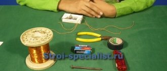
How to make a 12v electromagnet
The easiest way to make an electromagnet is to take a regular nail, wire and battery. An insulated wire is wound along the entire length of the rod. The ends of the conductor are pressed against the poles of the battery. To ensure that the charge is not wasted, one end of the wire is soldered to the positive contact. The other ending should be made in the form of a spring-loaded arc, which is pressed against the battery terminal with a minus sign. The bottom photo shows how you can make an electromagnet at home.
DIY electromagnet
Note! When making an electromagnet with a battery, you can use a contact block from an old device. To turn off the magnet, it will be enough to remove the battery from the contact box
Magnetic field created by the coil
When electric current passes through the windings of the coils, it behaves like an electromagnet. The plunger located inside the coil is attracted to its center by the magnetic flux inside the coil body, which in turn is compressed by a small spring attached to one end of the plunger.
The force and speed of movement of the plungers are determined by the strength of the magnetic flux generated inside the coil.
When the supply current is turned off (de-energized), the electromagnetic field previously created by the coil is destroyed, and the energy stored in the compressed spring forces the piston to return to its original resting position. This back and forth movement of the plunger is known as the "stroke" of the solenoids, in other words, the maximum distance the plunger can travel in the "in" or "out" direction, for example 0-30mm.
This type of solenoid is usually called a linear solenoid due to the linear directional movement and plunger action.
Rotary solenoid
Most electromagnetic solenoids are linear devices, producing linear force or forward and reverse motion. However, there are also rotary solenoids that produce angular or rotational movement from a neutral position in either clockwise, counterclockwise, or both directions (bidirectional).
Rotary solenoids can be used to replace small DC motors or stepper motors if the angular motion is very small and the rotation angle is the angle offset from the start to end position.
Operating principle
When current flows through a conductor, a magnetic field is created around it. This magnetic field can be strengthened by shaping the conductor into a coil shape. But still this is not an electromagnet. Now, if you place a core made of ferromagnetic material (for example, iron) into this coil, then it will become an electromagnet.
When current flows through the winding of an electromagnet, it creates a magnetic field, the lines of which penetrate the core, that is, the ferromagnetic material. Under the influence of this field, in the core, the smallest areas that have miniature magnetic fields, called domains, take on an ordered position. As a result, their magnetic fields add up, and one large and strong magnetic field is formed, capable of attracting large objects. Moreover, the stronger the current, the stronger the magnetic field that is formed by the electromagnet. But this will happen only until magnetic saturation. Then, as the current increases, the magnetic field will increase, but only slightly.
If the current in the electromagnet is removed, then the domains will again take a disordered position, but some of them will still remain in the same direction. These remaining directional domains will create a small magnetic field. This phenomenon is called magnetic hysteresis.
Permanent magnets. What is this?
The Chinese, like the Greeks, also noticed the interesting property of some minerals to attract iron-containing objects. The Chinese associate the word “attract” with the words “to cuddle” and “to love” and therefore called such minerals “chu-shi”, which means “loving stone”. Since these minerals were created by nature, and man could not influence the natural action of the stones, they began to be called permanent magnets.
It is now known that the natural mineral magnetic iron ore (magnetite) manifests itself in such an interesting way. This is a fairly fragile black mineral, its density is approximately 5000 kg/m3.
Magnetic iron ore.
Ancient people attributed the properties of a “living soul” to magnetic iron ore. The mineral, they said, rushed to the iron like a dog to a piece of meat. Scientists explain the attitude of the ancients to natural phenomena by ignorance of physics.
In fact, everything lies in a special type of matter - a field.
The magnetic field attracts iron objects to a permanent magnet, because, for example, small nails or buttons rush to the magnet even without contacting it, but at some distance.
Magnetite (natural magnetic iron ore) does not exhibit very strong attractive properties. Man has created artificial magnets with a more powerful magnetic field based on it. The materials used in them are metals such as cobalt, nickel and, of course, iron. Such metals are capable of magnetization when exposed to a magnetic field, and then become independent magnets.
Different forms of artificial magnets.
Whatever shape a magnet has, it has areas where its magnetic properties are most pronounced. These areas are called magnetic poles. Every magnet, even the smallest one, has two poles. Modern technologies make it possible to magnetize metal objects so that they form both 4 and 6 poles.
You can see how differently iron filings are attracted to a magnet in a simple experiment with an arched school magnet. Just bring a magnet to the sawdust, the sawdust will immediately “stick” to it:
Arc magnet.
The poles of such a magnet will be the edges of the arc, where the most iron filings have accumulated.
A strip magnet, shaped like a rectangular parallelepiped, has poles far apart from each other. The closer to the middle, the less magnetic properties appear.
Strip magnet.
Classification
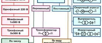
Electromagnets are divided into three types according to the method of creating magnetic flux
- AC electromagnets
- Neutral DC electromagnets
- Polarized DC Electromagnets
In alternating current electromagnets, the magnetic flux changes both in direction and in value, the only difference is that it changes with twice the frequency of the current.
In neutral DC electromagnets, the direction of the magnetic flux is independent of the direction of the current.
In polarized DC electromagnets, as you already understood, the direction of the magnetic flux depends on the direction of the current. Moreover, these electromagnets usually consist of two. One is a permanent magnet, which creates a polarizing magnetic flux, which is needed when the main, working electromagnet is turned off.
Calculations
Before you start assembling an electromagnet with your own hands, make a preliminary calculation of its parameters. Structural elements are calculated separately for DC and AC EVs.
For DC
Before making calculations, the required value of the magnetomotive force (MF) of the coil is determined. The winding parameters must provide the required MMF, at the same time the coil must not overheat, otherwise the insulating layer of the winding wire will be lost. The initial data for the calculation are the voltage in the wire of the electromagnetic coil and the required value of the magnetomotive force.
Methods for calculating DC electromagnets are constantly published on the Internet. There you can also select formulas for determining the MMF, the cross-section of the core and winding wire, and its length.
Additional Information. Mostly on the Internet they look for calculations of 12 volt electromagnets made by themselves. Depending on your needs, you can take different calculation paths. Basically, “recipes” are chosen to determine the cross-section and length of the winding wire powered by a standard “A” or “AA” format battery.
For AC
The basis for EM AC is the calculation of the winding. As in the previous case, they are guided by the initial requirements for the MMF value. Despite the large number of recommended calculation formulas, most often the “capabilities” of a device are determined by an experienced selection of the parameters of its design parts. Methods for calculating EM alternating current can always be found on the World Wide Web (Internet).
Superconducting electromagnet
The difference between a superconducting electromagnet and a conventional one is that, instead of a usual conductor, a superconductor is used in its winding. At the same time, its winding is cooled with liquid helium to very low temperatures. Its advantage is that the current in it reaches very high values, due to the fact that the superconductor has practically no resistance. Therefore, the magnetic field becomes stronger. The operation of such electromagnets is cheaper, since there are no heat losses in the winding. Superconducting magnets are used in MRI machines, particle accelerators and other scientific equipment.
Examples of using EM
The following devices can be cited as examples of the use of electromagnets:
- TVs;
- transformers;
- car starting devices.
TVs
Modern homes are usually filled with various electrical appliances. Being near a television receiver, they can influence the television screen (TV) by magnetic induction. TV already has built-in protection against screen magnetization. If multi-colored spots appear on the display field, then turn off the device for 10-20 minutes. Built-in protection will remove magnetization of the screen.
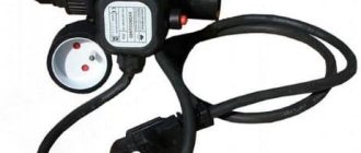
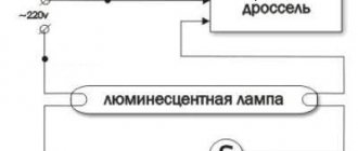
In some cases, this method does not provide the desired help. Then a special electromagnet is used, which is called a choke. This is a kind of induction coil. The device is connected to a household power outlet and passed along and across the screen. As a result, the induced magnetic fields are absorbed by the inductor.
Transformers
The design of transformers is very similar to the structure of electromagnets. Both there and there there are windings and cores. The difference between a transformer and an EM is that the former has a closed magnetic circuit. Therefore, the summed magnetic force is nullified by counter magnetic fluxes.
Car starting device
The car starter works as a starting device for the engine. It turns on while the engine is starting. The temporary transfer of starting force to the engine crankshaft is provided by a retractor electromagnet.
When you turn the key in the ignition switch, the EM pulls the gear into the crankshaft teeth. During contact, the starter motor cranks the engine until a fuel combustion cycle occurs in the engine cylinders. The traction relay then turns off the electromagnet and the starter gear returns to its original position. After which the car can move.
Starter with traction relay
Electromagnets have entered the sphere of human activity so tightly that existence without them is unthinkable. Simple devices can be found everywhere. Knowledge of the principle of their operation will allow the home handyman to cope with minor repairs of household electrical devices.
Operating principle
The simplest electromagnet is obtained when a steel core is placed inside the solenoid, and an electric current is passed through the turns. As a result, the core is magnetized, which acquires the properties of a permanent magnet. Thus, an electromagnet is obtained in which the steel core, in the absence of electric current, is completely demagnetized.
The magnetic field created by the electromagnet is significantly higher than the field of the solenoid. In this case, the field of the core is superimposed on the field of the solenoid and, ultimately, the combined magnetic field obtained when exposed to electric current increases significantly.
This invention is widely used in electrical engineering as DC electromagnets. This design is mainly used in actuators, most often in braking devices of various lifting mechanisms.
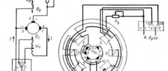
DC electromagnet design
In practice, there are DC electromagnets with a magnetically conductive body having flanges. A coil is installed in the housing, inside which two anchors are placed. The anchor poles have a truncated cone shape, allowing them to interact with each other. The armatures are separated from the coil and flanges. They are equipped with rods having ball joints at the ends, providing connection with external loads.
In addition to this, the electromagnet has two limiters located on the armatures. These limiters ensure that the anchors come into contact with each other at a certain point when they move towards each other. Additional separation of the anchors from the coil and flanges is carried out using special sleeves made of non-magnetic materials.
Electronic control for lifting electromagnets
When it becomes necessary to control it using an external device or microcontroller circuit, an appropriate circuit based on a conventional bipolar transistor or MOSFET is required. The circuit diagram below shows the simplest form of solenoid drive and can be used to drive most low power lifting solenoids.
The device requires a voltage input (VIN) to drive the electromagnet, and a control input signal (SIG) from the controller or timing unit that switches the power MOSFET, allowing the excitation current to excite the electromagnet. An additional diode located parallel to the electromagnet is designed to protect the field-effect transistor from an inductive voltage surge that occurs when the electromagnet is de-energized.
Additional electromagnet designs
In most designs, the coincidence of the armatures along the axes is ensured using a centering unit, which is a shaft made of non-magnetic materials. One end of this shaft is rigidly fixed in the axial hole of the first armature and has the ability to move along. The other end of the shaft is installed in the axial hole of the second armature using plain bearings.
This design is not reliable enough, since there is a possibility of jamming of the free end of the shaft due to foreign objects. This problem is solved by DC electromagnets used in the centering unit and ensuring reliable operation of the shaft when one of its ends is jammed.
Source