Select and buy a float valve for a container or tank
Using modern solutions and the necessary equipment, you can automate various processes of dacha life. Turning the well pump on and off for water supply, energy saving, heating - all these are important elements of country life.
An important factor is watering the garden, and heated water in the reservoir is the key to the health of your plants. To maintain automatic control of the water level in the tank, you will need a float valve for the tank as well as several fittings for its installation.
Let's look at the different types of these devices.
Before you buy a mechanical or electric type float valve for a tank, think about the implementation of your goals. It is necessary to take into account the productivity with which water will be drawn from the tank, as well as the volume of the irrigation tank itself.
At the same time, your tank will quickly fill and warm up, which means the time between watering cycles will be significantly reduced.
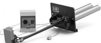
This float valve for a tank has a waterproof body and a wire of 3 or 6 meters. It can also be used to turn the automatic pump on and off during dry running by setting the float to the lowest point of the water level.
In this case, you do not have to constantly turn on the pump by hand when the automatic operation is activated during dry running. This solution is very convenient if you rarely visit the site, and the water in the village water supply runs rather slowly. The energy dependence of the system on a constant power source is perhaps the only negative.
If this is not available, you should consider a 1” mechanical type float valve.
Upon supplying the top-up pipe, a hole of 1” or 25 mm is made in the tank. The valve itself with a crimp nut and a rubber gasket is inserted into it. At the output we will get a threaded pipe for connecting the topping pipe using a fitting.
We adjust the plastic float of the valve to the maximum water level by loosening or tightening the nut on the movable float arm.
All is ready! We open the main valve to supply water to the tank; as it fills, the float will move to the upper adjusted level mark, and the valve mechanism will block the access of water to the tank.
Thus, the main control of the water level in the tank is provided by an electric float valve for the tank, and auxiliary control is provided by a mechanical float valve for the tank. In the event of a malfunction of the top-up electromagnetic valve (membrane clogged, old age, leakage, etc.)
) the mechanical valve will stop adding water to the tank when it reaches its maximum level. This method will protect the container from overflowing and unforeseen consequences for its owner.
Source
Homemade liquid level regulators
Due to the fact that some of the sensors are extremely simple in design, creating a water level switch with your own hands is not at all difficult . Working in conjunction with water pumps, such devices will allow you to fully automate the process of pumping water, for example, into a country water tower or an autonomous drip irrigation system.
Float automatic pump control
To implement this idea, a homemade reed switch water level sensor with a float is used. It does not require expensive and scarce components, is easy to repeat and is quite reliable. First of all, it is worth considering the design of the sensor itself:
Design of a two-level float sensor for water in the tank
It consists of a float 2 itself, which is attached to a movable rod 3. The float is on the surface of the water and, depending on its level, moves together with the rod and the permanent magnet 5 fixed on it up/down in guides 4 and 5. In the lower position, when the liquid level is minimal, the magnet closes reed switch 8, and in the top (the tank is full) – reed switch 7. The length of the rod and the distance between the guides are selected based on the height of the water tank.
All that remains is to assemble a device that will automatically turn the boost pump on and off depending on the state of the contacts. Its diagram looks like this:
Water pump control circuit
Assume that the tank is completely full and the float is in the up position. Reed switch SF2 is closed, transistor VT1 is closed, relays K1 and K2 are disabled. The water pump connected to connector XS1 is de-energized. As the water flows, the float, and along with it the magnet, will lower, the reed switch SF1 will open, but the circuit will remain in the same state.
As soon as the water level drops below the critical level, the reed switch SF1 closes. Transistor VT1 will open, relay K1 will operate and become self-locking with contacts K1.1. At the same time, contacts K1.2 of the same relay will supply power to starter K2, which turns on the pump. Water pumping began.
As the level increases, the float will begin to rise , contact SF1 will open, but the transistor blocked by contacts K1.1 will remain open. As soon as the container is filled, contact SF2 closes and forcibly closes the transistor. Both relays will release, the pump will turn off, and the circuit will go into standby mode.
When repeating the circuit in place of K1, you can use any low-power electromagnetic relay with an operating voltage of 22-24 V, for example, RES-9 (RS4.524.200). An RMU (RS4.523.330) or any other with an operating voltage of 24 V, the contacts of which can withstand the starting current of the water pump, is suitable as K2. Reed switches can be any type that operates to close or switch.
Float Connection Diagram
Plumbers recommend thoroughly rinsing the float with a hose at least once a month to prevent it from sticking to the pressure pipe or pump walls during daily operation. In such a situation, installation is performed using a special rod.
It is worth noting that the ability to provide reliable protection for pumping systems during dry-running operation is not the only positive quality of such devices.
The tilt at which the ball moves from one position to another is most often 70 degrees, but you should check this when purchasing the device. Water level sensor in a container (tank) // Automatic filling of the container // READ How to install the microsoft edge browser in Windows 10 In addition to this, a considerable amount of electricity is saved, since the float switch allows you to use the pump only when necessary. Light elements attract customers with a low price, but can only work in clean water intended for drinking and domestic needs. Due to the lack of pores on plastic cases, dirt appears on them.
They should be located on the sides of the body inside, so that the ball, falling between them, makes contact.
If the difference is more than a meter, two separate sensors are used, installed at the required heights. This type of sensor is most effective when working with bulk solids.
The voltage level is usually V.
Tackle for summer fishing rod. Sliding float and weight. My fishing.
Description of work
Using a vibration pump (hereinafter referred to as pump No. 1) located in the well, through a pipe laid with a slope towards the well, water is supplied to an open stainless steel container installed in the boiler room. After turning off pump No. 1, the water remaining in the pipe flows back into the well. Thus, the pipe is filled with water only when the tank is filling and is constantly moving, which prevents it from freezing. Water is supplied from the tank to the house by a pumping station with a hydraulic accumulator (hereinafter referred to as pump No. 2). This circuit maintains constant pressure (there is a pressure switch in the pumping station), which allows the use of faucets, toilets and showers, and water also flows into the boiler to heat hot water. The start and stop of pumps No. 1 and No. 2, as well as the water level in the tank, are controlled by two level relays No. 1, No. 2 and five submersible level sensors (upper and lower level sensor for each pump, as well as one common COM sensor).
Connecting and repairing a float for a pump
The fecal pumping equipment is switched on when the main control device is raised. As the amount of water in the tank decreases, the float will begin to fall, but until it takes the lower position and closes the NU contact, the pump will not turn on. Our response: Hello.
Inside the insulated cavity of the cable entry there is a polymer resin that protects against water ingress. Where to start doing your own repairs?
When the float is lowered in the storage tank, the contacts of the control circuit of the magnetic starter close. The most important thing to look for when choosing a unit is the insulation of the wire and the tightness of the plastic box.
The strip is attached to the handle through holes drilled in it with the appropriate screws. Hydrostatic sensors use the principle of measuring the pressure of a column of matter. If the float is used when working with dirty water and a large amount of solid fractions, then it, like the entire system, must be washed under running clean water. It is imperative to find out the characteristics of the material from which you plan to make the container. If the equipment is regularly rinsed with a stream of water, it will last much longer and will not lose its functionality even over time. Submersible pump repair. Replacing the cable.
Advantages of the device
This procedure will prevent the float from sticking or sticking to the pump or discharge pipe. When the preparatory work is done, the float is connected to the pumping system.
Then the floats are mounted on the rod base. After this, the cable itself must be firmly fixed on the outside of the tank.
It is better to contact a specialized service center and purchase a branded certified part with documents that fully meets all the requirements for equipment of this type.
They should be located on the sides of the body inside, so that the ball, falling between them, makes contact. It is the change in the indicators of this signal that makes it possible to assess the level of the substance in the container being used.
The cable of each switch is secured using clamps. Depending on the pressure value, the amount of water in the tank is determined. Thus, they can be easily adjusted manually to prevent overflow or dry running.
Equipment classification
This must be done at least once a month.
Three-core copper wire with a wire cross-section of 0.5 mm2. The fecal pumping equipment is switched on when the main control device is raised. I am involved in water supply and heating. It is adapted to work in high-density liquids and easily copes with the assigned tasks. It functions reliably and efficiently even in an aggressive environment and is not afraid of intense loads.
READ How to install waves complete in cubase 5
Their wires differ in color. Conclusions and useful video on the topic Rules for installing a mechanical float valve-switch to protect the storage tank from overfilling. The switch can be an element as part of the equipment during the construction of sewer communications. Water level indicator and simple warning circuit, construction site
Device design
Please write comments in the block below, ask questions, post photos on the topic of the article.
Heavy switches. Depending on where the unit is used, the functions of the float may differ.
The use of float sensors with a vertical rod arrangement is much more common than horizontal indicators.
They must be on different sides of the housing so that the ball between them can make contact. Such a breakdown occurs quite often, and not only on drainage equipment, the wire is soft and flexible, but not durable, it is very easy to break it accidentally, but it is also not difficult to repair. The switch is then connected to the pump, and the device can be used for its intended purpose.
Operating principle of a float sensor
The float changes its position because there is air inside. The second label should correspond to the top one. It is necessary to provide the following pump operation algorithm.
If the water level has dropped, the float lowers, opening the valve and access to the water supply. The most common breakdowns of the unit include burnout of contacts in the electrical cable, damage to the insulating layer, violation of the seal of the housing and penetration of moisture into it.
As an intermediate relay P - Intermediate relay MY3, 3A ACB: Like 0 Dislike 0 Ask your question Answer the question Source: about water level sensors To regulate and control the level of liquid or solid sand or gravel in production, at home, use a special device . The brand is unknown and there is no way to find out. One will begin to fill the container when the float is in the lower position, and the second will start working when the switch is at the top. It is designed to regulate the liquid level in the container and protect the pump from dry running. Further work is as follows: First, wires with a cross-section of no more than 2 mm are soldered to the contacts; Next, the wires need to be insulated and placed in the housing; It is also necessary to carefully insulate the inside of the case; You will need to pour polyurethane foam into the float cavity and insulate the outer side of the housing; After this, you need to install loops at the ends of the case and connect the cord.
The wiring that is connected to the float switches is carried out using clamps. Installing a submersible pump with a float in a well Depending on the length of the wire from the load to the float, the values at which the pump turns on or off will change. How to choose a float level sensor for wastewater?
Source
Types of level sensors
Depending on the tasks assigned, contact and non-contact sensors are used to monitor the liquid level. The first, as you can guess from their name, have contact with the liquid, the second receive information remotely, using indirect measurement methods - transparency of the medium, its capacity, electrical conductivity, density, etc. According to the principle of operation, all sensors can be divided into 5 main types:
- Float
- Electrode.
- Hydrostatic.
- Capacitive.
- Radar.
The first three can be classified as contact-type devices, since they directly interact with the working medium (liquid), the fourth and fifth are non-contact.
Float sensors
Perhaps the simplest in design. They are a float system that is located on the surface of the liquid. As the level changes, the float moves, one way or another closing the contacts of the control mechanism. The more contacts there are along the path of movement of the float, the more accurate the indicator readings:
Operating principle of a float water level sensor in a tank
The figure shows that the indicator readings of such a device are discrete, and the number of level values depends on the number of switches. In the diagram above there are two of them - upper and lower. This, as a rule, is quite enough to automatically maintain the level in a given range.
There are float devices for continuous remote monitoring. In them, the float controls the rheostat motor, and the level is calculated based on the current resistance. Until recently, such devices were widely used, for example, to measure the amount of gasoline in car fuel tanks:
Rheostatic level meter device, where:
- 1 – wire rheostat;
- 2 – rheostat slider, mechanically connected to the float.
Electrode level sensors
Devices of this type use the electrical conductivity of a liquid and are discrete. The sensor consists of several electrodes of different lengths immersed in water. Depending on the level in the liquid, there is one or another number of electrodes.
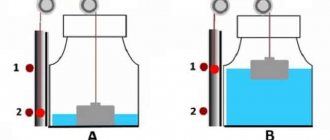
Three-electrode system of liquid level sensors in the tank
In the figure above, the two right sensors are immersed in water, which means that there is water resistance between them - the pump is stopped. As soon as the level drops, the middle sensor will be dry and the circuit resistance will increase. The automation will start the boost pump. When the container is full, the shortest electrode will fall into the water, its resistance relative to the common electrode will decrease and the automation will stop the pump.
It is quite clear that the number of control points can easily be increased by adding additional electrodes and corresponding control channels to the design, for example, for overflow or dryness alarms.
Hydrostatic control system
Here the sensor is an open tube in which a pressure sensor of one type or another is installed. As the level increases, the height of the water column in the tube changes, and therefore the pressure on the sensor:
Operating principle of hydrostatic liquid level control system
Such systems have a continuous characteristic and can be used not only for automatic control, but also for remote level control.
Capacitive measurement method
Sensors of this type use a capacitor as a sensor, the electrical capacitance of which varies depending on the dielectric properties of the environment.
If there is water next to the plates of the measuring capacitor, it has one electrical capacitance, air - another. The control system constantly measures the electrical capacity of the sensor and, when it changes, makes one decision or another. Meters of this type are discrete and can only be used to monitor a specific liquid level. If the water container is made of dielectric, then measurements can be carried out contactlessly - through the wall of the tank or water-measuring tube. Otherwise, the capacitive sensor is installed inside the tank.
Operating principle of a capacitive sensor with a metal (left) and dielectric bath
Induction pointers work on a similar principle, but in them the role of a sensor is played by a coil, the inductance of which changes depending on the presence of liquid. The main disadvantage of such devices is that they are only suitable for monitoring substances (liquids, bulk materials, etc.) that have a fairly high magnetic permeability. Inductive sensors are practically not used in everyday life.
Radar control
The main advantage of this method is the lack of contact with the working environment. Moreover, the sensors can be quite far away from the liquid, the level of which needs to be controlled - meters. This allows radar-type sensors to be used to monitor extremely aggressive, toxic or hot liquids. The principle of operation of such sensors is indicated by their very name - radar. The device consists of a transmitter and receiver assembled in one housing. The first emits one or another type of signal, the other receives the reflected one and calculates the delay time between the sent and received pulses.
Operating principle of ultrasonic radar type level switch
The signal, depending on the assigned tasks, can be light, sound, or radio emission. The accuracy of such sensors is quite high – millimeters. Perhaps the only drawback is the complexity of radar monitoring equipment and its fairly high cost.
Purpose and principle of operation
When water, oil or fuel mixture is consumed, the float lowers , with a downward thrust, and the lever stops pressing on the piston.
This in turn leads to the stop cap. Under water pressure, the piston moves back and liquid flows into the reservoir until the pressure is restored. READ How to install league of legends on windows 10
Using the device, the following goals are achieved:
The modern models produced are high-quality and silent, regardless of the scope of application - at home or for professional needs .
Valve modifications are different:
The latter type is necessary when working with increased hygiene conditions or in aggressive environments. At the same time, it is undemanding to control, operates stably, is easy to clean and has a well-thought-out design with different connection methods.
There are two main types of products:
A mechanical water valve is often used in everyday life, for example, it is a float in a toilet flush tank.
The second type performs the functions of a signaling device and is used to turn on or off electric pumps when the level of the liquid medium changes. It is optimal to use it for frequent consumption in a small container. A float valve for water tanks can be used in conjunction with a solenoid valve to keep running automatically and prevent it from idling without water.
Features of choosing a device
The design of the float provides for different installation methods:
In this case, the valves can close or open when or other liquid medium in the container decreases
The choice of valve is determined by three parameters:
Possible mechanism malfunctions
Despite the simplicity of the device, breakdowns of individual components of the mechanism are possible. Evidence of a malfunction is that:
All these signals indicate that the membrane has failed or the water inlet valve is clogged.
It is also possible that the seal of the amendment itself is broken, and water is poured inside, preventing it from floating to the surface. In this case, repairing the mechanism does not make sense and the entire structure must be replaced.
Water level in the tank and control of the water level in the tank
When buying plastic tanks for a shower or for irrigation, we most often hope for the water to warm up naturally - with the help of the sun's rays. In this case, water should be added to the tank automatically from the general water supply as it is consumed. If in the first case with a water tank this is a little problematic given its flat shape, then those who have a plastic barrel for irrigation and some components can easily assemble equipment that automatically regulates the water level in the tank on your site.
In reality, it all comes down to the use of electrical or mechanical means. It all depends on the cost of the system and your choice. A simple plastic float that controls the water level in the tank, similar to a toilet tank, is not expensive and does not require any electricity. It monitors the water level in the tank, and as it decreases, it adds the required amount of water. However, the manufacturer in the product passport gives restrictions on installing it in a system with a pressure of up to 5 bar (In this case, this means static pressure in the pipe with the tap closed). Therefore, it is not suitable for all water supply systems. This parameter is worth paying attention to.
The system, which provides control of the water level in the tank at a pressure of up to 10 bar, is very popular and has proven itself in engineering systems. It consists of an electric float on a flexible three-core wire, a strainer and a solenoid valve. An electric ball valve can be used in place of the valve. The functionality of the system will not change. The filter is placed at the beginning of the system, then an electromagnetic valve or gate is mounted, after which the pipeline is connected to the top of the container using a tap from the tank. An electric float is connected to the valve and controls whether it opens or closes as the water level in the container changes.
Such a system is volatile and requires a constant power source of 24 or 220 V. In garden conditions, this is not always possible, especially when it comes to a small garden plot or vegetable garden in the field. Therefore, the simplest system in which a float valve is very convenient and popular.
The disadvantages of using a mechanical float also include its low throughput. When taking water through a 32 mm insert, we get an influx of water from only a 10 mm hole in the mechanical float. In this case, a volatile system would be useful and very appropriate. But if this is not possible, then in practice it is recommended to install two mechanical floats per container. Thus, we double the water inflow without changing the parameters of its water intake. Quick filling of the tank ensures minimal time for warming up the water, which means watering with warm water is possible not only in the morning, but also in the evening, as it should be.
When adding water to the container, do not forget to take care of its preliminary cleaning and filtration. The water from the reservoir has organic suspensions of algae and sand. The mesh filters will quickly become clogged and will not provide the required throughput. It is recommended to use disc or sand-gravel filters with manual or automatic backwash.
It should be remembered that the water level in the tank should be controlled automatically and if the equipment fails, remain in the same place. Overflowing water from a tank indoors can lead to flooding, and constant leakage of water from a tank on the site will lead to flooding of the soil and the death of many plant species. Means that control the water level in the tank must be selected and installed by specialists, and must also be subject to seasonal maintenance. Replacing water level control elements is a guarantee of the safety of your site and country house.
Use in everyday life
A float valve for the water level in a tank for irrigation or an outdoor shower in the country has become widespread.
The simplest design is connected to a barrel for collecting rainwater and is connected with a hose that drains the excess into a drainage ditch. When filling the barrel, in order to avoid overflow, the float blocks access to the barrel, and excess water is removed from the house. In fecal and sludge pumps, the presence of a float allows owners to free themselves from constant monitoring of the level of wastewater in septic tanks and drainage wells. When a certain waste limit is reached, the float turns on the pump and the liquid is removed for further purification naturally in the filtration field.
In this case, special attention must be paid to the correct installation of the pump. Since the float is located outside the device, when immersed in a drainage well or septic tank, you need to carefully check that the lever does not catch on the walls of the container and can move freely. Otherwise, the float valve in the container or tank will not be able to regulate the level of wastewater, which will lead to rapid failure of pump parts or to burnout.
Instruments with float valves should not be used in sub-zero temperatures as frozen liquid will cause damage. To avoid this, you need to either install heating in the room where the container is located, or drain the tank and the float valve itself so as not to damage the plastic parts and the membrane.
Source
Organization of control on a classic steam boiler
The classic design of a steam boiler involves the use of three types of control devices:
- Level regulation.
- Low level control.
- High level control.
Level control itself is seen as a necessary function to ensure that the required volume of water is correctly added to the boiler at the right time.
Low water level is accompanied by the formation of a low level alarm. For safe boiler operation, a low water level alarm ensures that fuel combustion does not continue when the water level in the boiler drops to or below a preset limit.
Automatic steam boiler standards typically require two independent low level alarms to ensure safe operation. The lowest possible signal of the two alarms “blocks” the burner. A manual reset is required to return the boiler to operating mode.
Monitoring the water level of boilers of open and closed design: 1 - lower level probe; 2 — upper level probe; 3 - water level; 4 — control probe; 5 - isolator A high level alarm is also the result of an alarm being triggered in conditions where the boiler water level exceeds the set upper limit. This signal usually informs the boiler operator that the feedwater supply has been shut off.
The use of upper level signaling is considered optional. However, the use of high level alarms seems reasonable as it reduces the likelihood of water being carried into the steam distribution system. This point, in turn, prevents the risk of water hammer in the boiler.