Application area
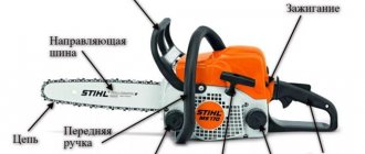
Throttle is designed to make our lives brighter. Specifically in fluorescent lamps, it limits the current through the bulb to the desired value, avoiding its excessive increase through the lamp.
The fluorescent lamp is mainly composed of choke, starter, fluorescent lamp. In a nutshell, the description of how a fluorescent lamp works is as follows:
From the network, the current passes through the inductor to one of the filaments of the fluorescent lamp, then it goes to the starter device, then to the second filament and goes into the network. In the starter device, a bimetal plate is heated by a glowing gas discharge, straightens under the influence of heat and closes the circuit. At this moment, the filaments at the ends of the light bulb begin to work, heating the mercury vapor in the bulb of the fluorescent lamp. After a short period of time, the plate in the starter cools down and returns to its original position. When the circuit breaks, there is a sharp surge in voltage in the inductor, gas breakdown occurs in the bulb of the fluorescent lamp, and a glow discharge occurs, the lamp begins to shine, the working lamp shunts the starter, turning it off from the circuit with a lower resistance.
The electronic circuits of modern economic fluorescent lamps also contain the element discussed in the article, but due to higher frequencies it has miniature dimensions. But the operating principle and purpose remain the same.
Also, the inductor is a mandatory element in the circuits of DRL lamps, HPS sodium lamps, and CDM metal halide lamps.
In switching power supplies in converter circuits, the purpose of the inductor is to block sharp surges from the transformer, passing a smoothed voltage. Roughly speaking, in this case it plays the role of a filter.
They are also installed in electrical networks, but are called reactors. The purpose of the arc suppression reactor is to prevent the occurrence of an independent arc during a single-phase short circuit to ground, as well as other reactors that somehow regulate or limit the amount of current through them, specifically or in case of an emergency.
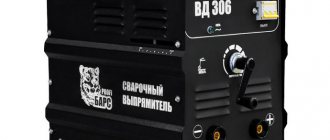
Using a choke, you can improve a cheap or homemade welding machine by installing it in the secondary circuit. A welding transformer assembled with a choke will weld no worse than branded devices, the arc will become smooth and will not break, the seam will be evenly filled.
Ignition of the arc will become much easier and the mains voltage drop will have less effect on the appearance and burning of the arc. Even a non-specialist can quickly achieve good results in welding by making all kinds of crafts at home.
So we looked at the design of the throttle, its operating principle and purpose. We hope that you now fully understand why this element of the circuit is needed!
Mechanical or electric damper: which is better?
We found out that the throttle valve is the very valve that makes the engine spin faster or slower, regulating the supply of oxygen to its cylinders.
Now let's look at the varieties of this device and their design. There are the following types of dampers:
- with mechanical drive;
- with electric drive.
The mechanical system is a classic and is found not only on old cars, but also on quite modern ones, but only in the budget segment.
Its essence lies in the fact that the connection between the gas pedal and the damper is carried out by a simple metal cable. The logic of the device’s operation is elementary - press the gas, the throttle opens and lets air into the cylinders.
In addition to the rotating damper itself and the cable going to it, the assembly includes a position sensor and an idle speed regulator.
The purpose of the first is clear - the sensor monitors how far the damper has opened and transmits this information, for example, to the engine control unit.
As for the regulator, it is needed so that at idle the engine receives the portion of oxygen necessary for minimum speed. It is a separate small valve with an electric drive.
What is an Electric Throttle?
It is much more modern and technologically advanced. The main difference from the mechanical system is that there is no direct connection with the pedal; everything is controlled electronically.
In this case, individual sensors monitor how hard we press the gas and the computer decides how much to deflect the throttle using an electric drive.
By the way, in this version there is no need to install a separate valve to adjust the idle speed - the air passes through the main throttle valve in any case.
By the way, the advantages of the electrical system over the mechanical mass. Since the entire process is driven by electronics, it is possible to achieve better engine efficiency and lower emissions of harmful substances.
In short, mechanical options, although simple in design, are already obsolete not only physically, but also morally.
I hope that now you will not have the question: “What is a throttle valve and why is it needed?” Subscribe, because the publication of articles about the structure of cars continues.
OUTPUT PROTECTION ELEMENTS
The operating principle of most frequency converters used today is based on pulse width modulation of output voltage pulses ( PWM - Pulse Width Modulation; PWM - pulse width modulation
). The voltage thus obtained is in the form of a train of pulses with a very short rise time (high slope) and the voltage is not sinusoidal. This is a positive for the inverter since switching over a short period of time allows it to be maintained at a level where losses in the inverter are kept to a minimum. However, the steepness of the voltage rise (du/dt) of the output pulses, as well as the increasing switching frequency used in inverters, can cause parasitic phenomena in the motor cable and in the motor itself. These phenomena significantly affect the reduction in engine durability and increase the likelihood of failure of the drive system as a whole. Most frequently encountered problems:
a) high rate of voltage slew (du/dt)
– with a small distance between the inverter and the motor, the high slope of the inverter output voltage has a negative effect on the cable insulation and its winding. In modern converters, slope values reach 10 and even 12 [kV/µs], while in motors the permissible slope of the voltage rise should not exceed 1 [kV/µs].
b) overvoltage at motor terminals
– is the result of resulting wave phenomena that are sometimes called the “Long Line Effect,” “Reflected Wave Effect,” or “Standing Wave Effect.” With a cable length of approx. 10 [m] signs of the effect are already observed. The main insidiousness of these high-frequency overvoltage pulses is that the motor is “killed” for a long time and often the failure of the motor is not associated with its power supply from the PWM inverter. The motor is rewound or a new one is installed and after a while everything repeats. An equivalent circuit of a cable power line can be represented as a series connection of parasitic capacitances and leakage inductances of the cable line:
a) diagram of the drive system (inverter – cable – motor); b) the slope of the inverter output voltage; c) overvoltage at motor terminals
Fig.4. Voltage on the motor winding without a choke.
Fig.5. A single pulse of the inverter output voltage (upper oscillogram) and the voltage at the motor terminals (lower oscillogram). No throttles. Cable length 211m, PWM frequency 2 kHz, frequency converter 0.75 kW, asynchronous motor 0.75 kW, 2820 rpm
Fig.6. Motor voltage (upper waveform) and current (lower waveform). No throttles. Cable length 211m, PWM frequency 2 kHz, frequency converter 0.75 kW, asynchronous motor 0.75 kW, 2820 rpm
Even with low inductance, a sequence of voltage pulses of high transconductance leads to overvoltage. As the cable length increases, its net inductance increases, and increased wave phenomena and overvoltage can damage the motor insulation. The magnitude of the overvoltage on the motor
can reach values of more than 1000V. While the permissible overvoltage value for a low-voltage motor for general industrial use is limited to 1000V; minimum voltage rise time 2 µs.
c) additional losses in the motor and power cable
– higher harmonics of voltage and current lead to additional losses in the power cable, motor core and winding, especially in the “squirrel cage” of the rotor. This reduces the efficiency of the motor and the drive system as a whole. Additional losses are generated heat. Losses lead to an increase in the temperature of the motor and cable, accelerate the aging process of the insulation, thereby significantly reducing their service life. System reliability decreases.
d) screen, bearing and earth leakage currents
–d high-frequency components of the equivalent circuit of asynchronous motors and parasitic capacitances of the power cable are among those parameters that are almost always left aside, i.e.
are not taken into account when mains power is supplied. The values of these capacities range from a few to more than a dozen [nF] and are not significant for consumers. The problem only appears when the motors
by PWM inverters. At high switching frequencies, the resulting reactance of the parasitic capacitances of the cable and motor is reduced. The lower the value of the resulting reactance, the more current passes through the parasitic capacitances. The values of parasitic screen, bearing current and ground leakage current are summed up with the corresponding load of the converter (Fig. 1.a), which in a critical situation (for example, when using long cables) may lead to the need to change the inverter power and the cross-section of the power cable.
e) electromagnetic interference emissions
– the output voltage signal of the PWM inverter consists of the fundamental harmonic (Hz), carrier frequency band (kHz) and higher-order harmonics (MHz), resulting from the rapid switching of transistor switches.
It is the latter frequency range that is responsible for the emission of electromagnetic interference. This interference spreads evenly in all directions, and the motor cable, together with the PWM inverter, is the main source of electromagnetic interference in the entire automation
machine.
f) creating a high noise level
– in addition to the above-mentioned negative results of the manifestation of higher harmonics in the output voltage of the inverter, there is still the problem of noise. Higher-frequency harmonics result in motor whistling and “crackling” noise, which affects the operating comfort of the drive system.
Du/dt chokes
Effect of du/dt chokes type ED3Du
manifests itself in protecting the insulation of the motor windings from high-amplitude voltage pulses with a high rate of rise due to the peculiarity of modern PWM inverters and the “reflected wave” effect. Chokes are especially effective with short motor cable lengths and low switching frequency and are the bare minimum that the user must provide for reliable operation of the drive system.
Advantages of using du/dt chokes type ED3dU:
- increasing engine reliability and durability
- limitation of voltage rise slope du/dt
- successful suppression of electromagnetic interference in the frequency range from 1 to 30 MHz
Fig.7. Voltage curves before and after the choke du/dt type ED3dU.
Fig.8. Single voltage pulses at the output of the inverter (upper oscillogram) and motor (lower oscillogram). Du/dt choke type ED3dU-2.58/2.1 (2.58 mH, 2.1 A) at the inverter terminals 0.75 kW, 400 V, 50 Hz; PWM 2kHz, cable length 211m
Fig.9. Motor terminal voltage (upper waveform) and motor current (lower waveform). Du/dt choke type ED3dU-2.58/2.1 (2.58 mH, 2.1 A) at the inverter terminals 0.75 kW, 400 V, 50 Hz; PWM 2kHz, cable length 211m
Motor throttles
Motor chokes, unlike du/dt chokes, have a higher inductance and can therefore operate over long cable lengths and high switching frequencies. This is the most commonly used and successful device that protects the motor from the negative influence of the PWM frequency converter.
Advantages of using motor chokes type ED3S:
- increasing the reliability and durability of the motor
- limitation of voltage rise slope du/dt
- successful suppression of electromagnetic interference
- reducing the amplitude of overvoltages at the motor terminals
- reduction in engine noise
Fig. 10. Voltage curves in front of and behind the engine throttle.
Fig. 11. Single voltage pulses at the output of the inverter (upper oscillogram) and motor (lower oscillogram). Motor choke type ED3S-22.4/2.1 (22.4 mH, 2.1A) at the inverter terminals 0.75 kW, 400 V, 50 Hz; PWM 2kHz, cable length 211m.
Fig. 12. Motor voltage (upper waveform) and motor current (lower waveform). Motor choke type ED3S-22.4/2.1 (22.4 mH, 2.5 A) at the inverter terminals 0.75 kW, 400 V, 50 Hz; PWM 10 kHz, cable length 211 m.
How to test a throttle with a multimeter
We have figured out what a throttle is and what it is used for, now it’s also worth learning how to determine its performance. If the multimeter can measure inductance, everything is easy. We're just taking a measurement. If the throttle parameters are unknown to us, we set the largest measurement limit. Usually it's a few hundred Henrys. On the jackal they are designated by the Russian Gn or the Latin letter H.
Having set the multimeter switch to the desired position, we touch the coil terminals with the probes. A number appears on the screen. If the numbers are small, move the switch to one of the following positions, guided by the previous indicators.
Not all multimeters have an inductance measurement function.
For example, if 10 mH is displayed, we set the measurement limit to the nearest larger one. After this, we repeat the measurements. In this case, the inductance of the measured inductor will be displayed on the screen. Having passport data, you can compare real indicators with declared ones. They shouldn't be much different. If the difference is large, the throttle needs to be changed.
If the multimeter is simple, it does not have an inductance measurement function, but there is a resistance measurement mode, you can also check its performance. But in this case we will measure not inductance, but resistance. By measuring the winding resistance, we can simply understand whether the inductor is working or whether it is broken.
This way you can check the serviceability of the choke for fluorescent lamps
To test the throttle with a tester, move the multimeter switch to the resistance measurement position. We set the measurement limit, it is better to set the lower one in order to see the winding resistance. Next, use probes to touch the ends of the winding. Some resistance should appear. It should not be infinitely large (break) and should not be zero (short). In both cases, the throttle is not working, all other values are a sign of operability.
To make sure that there is no short circuit on the inductor turns, you can switch the multimeter to continuity mode and touch the leads with the probes. If it rings, there is a short, there is a breakdown somewhere, and this means that another choke is needed.
A choke is an inductor that has a high resistance to alternating current. In a DC circuit, the inductor has much less resistance. The name of the electrical component is of German origin - Throttle, which means smoothing, braking.
How does the throttle work?
In AC circuits, to limit the load current, chokes are often used - inductive reactors. Here, chokes have serious advantages over conventional resistors - significant energy savings and the absence of strong heating.
What is the design of the throttle, what is the principle of its operation based on? The structure of the inductor is very simple - it is a coil of electrical wire wound on a core made of ferromagnetic material. The prefix ferro indicates the presence of iron in its composition (ferrum is the Latin name for iron), in one quantity or another.
Without a choke, the circuit will work as usual - the circuit closes, the lamp lights up. But if you add a choke, connecting it in series with the load (light bulb), the picture will change somewhat. Taking a closer look, you can see that, firstly, the lamp does not light up immediately, but with some delay, and secondly, when the circuit is opened, a clearly visible spark appears, which has not been observed before. This happens because, at the moment of switching on, the current in the circuit does not increase immediately - the inductor prevents this, absorbing electricity for some time and storing it in the form of an electromagnetic field. This ability is called inductance.
The larger the inductance value, the more energy the inductor can store. The unit of inductance is 1 Henry. At the moment the circuit breaks, the stored energy is released, and the voltage can exceed the E.M.F. of the source used tens of times, and the current is directed in the opposite direction. Hence the noticeable sparking at the rupture site. This phenomenon is called E.M.F. self-induction.
If you install an AC source instead of a DC one, using, for example, a step-down transformer, you may find that the same light bulb connected through an inductor does not light up at all. The inductor provides much greater resistance to alternating current than to direct current. This occurs due to the fact that the half-cycle current lags behind the voltage.
Graphically it looks like this.
It turns out that the effective voltage across the load drops many times (and the current accordingly), but energy is not lost - it is returned through self-induction back into the circuit. The resistance provided by inductance to alternating current is called reactive. Its value depends on the magnitude of the inductance and the frequency of the alternating current. The amount of inductance, in turn, depends on the number of turns of the coil and the properties of the core material, called magnetic permeability, as well as its shape.
Magnetic permeability is a number showing how many times the inductance of a coil is greater with a core made of a given material than without it (ideally in a vacuum.) That is, the magnetic permeability of a vacuum is taken as one.
In low-inductance RF coils, rod-shaped cores are used for precise tuning. The materials for them can be ferrites with a relatively low magnetic permeability, sometimes non-magnetic materials with a permeability less than 1. In relay electromagnets there are horseshoe-shaped and cylindrical cores made of special steels.
To wind chokes and transformers, closed cores—magnetic cores Ш—shaped and toroidal are used. The material at frequencies up to 1000 Hz is special steel, above 1000 Hz - various ferroalloys. Magnetic cores are assembled from individual plates coated with varnish.
DNAT choke types and connection methods
In order to ensure ignition and equalization of the current of sodium lamps, both high and low pressure, when the lighting devices are connected to the network, a dnat choke is used, which includes ballasts and ballasts. These are the main devices, without which the use of sodium lamps is not possible that is inappropriate, but simply meaningless. In addition to the ballast, it is also necessary to purchase a pulsed ignition device, abbreviated IZU, which allows you to heat the lamp, using a pulse that allows you to create a discharge in the gas mixture.
Currently, two-winding chokes are considered obsolete, so they are used quite rarely. The ballast can be purchased both domestically and foreign; this statement also applies to the pulse ignition device. The main condition is that the power of the inductor and IZU must correspond to the power of the sodium lamp.
Choke for fluorescent lamp.
We note the fact that a pulsed ignition device (IZD) can be of two types. The first type includes two-wire IZUs, the second type includes IZUs with three wires. Accordingly, three-wire devices are more reliable, but at the same time their price is more expensive, so the question comes down to the economic feasibility of purchasing the product. The next term that refers to the concept of a throttle is ballast. Ballast is usually called a ballast and a pulse starting device, which have a metal body.
There are also open rights. The choice of an open or closed device depends on the preferences of the individual electrician. The advantages of lights in a metal case include a lower operating temperature, manufacturer guarantees regarding the assembly of the product, and a simpler installation scheme in lighting fixtures. Let's look at the dnat connection diagram. So, the main condition is that the power of the inductor matches the power of the lamp. For example, if you have a dnat choke of 600, then the sodium lamp should also be 600. The rule is simple, but if it is not followed, the operating life of the lighting device will be significantly reduced, and the light output will drop to a critical level.
The next point that you need to pay attention to is the installation diagram. In this case, it is necessary to take into account various parameters, among which we note the length of the wire from the lamp to the inductor. This distance should not exceed one meter.
Moreover, for connections it is necessary to use copper wire, monocore or stranded, with a cross-section of 0.75x1.5, although this is also an amateur question; you can take a wire with a larger cross-section, so to speak, with a margin. Pay attention to the issue of purchasing a power cord, it must also withstand heavy loads, the cross-section should be about 1.5 - 2.5 mm, even if the choke for dnat is 150. Approximate parameters of the choke are shown in the table below.
Table of calculations of the main properties of the inductor.
The next point we pay attention to is the need to install a fuse. Many will argue that this is a waste of money, but this statement is not true. The fuse, like a faithful guardian, will save you in the event of a breakdown of the ballast, when various troubles are possible, which can result in either a lamp explosion, a fire, or the banal knocking out of plugs if you do not have the bugs screwed on. It is best to purchase a two-pole machine, it is more convenient so as not to bother with how to insert the plug into the socket.
Worth reading: everything about electrolytic capacitors.
Moreover, the choice of machines must be approached with the utmost seriousness. As well as the purchase of other parts, such as a Dnat 250 throttle, ballasts or a pulse ignition device. Therefore, it is necessary to buy components exclusively at retail outlets that do not sell defective illiquid goods.
It will be interesting➡ What is a pulse relay
At the same time, it is better to overpay and buy a normal automatic machine or choke than to underpay and buy HPS control gear produced by Chinese industry. So that later it doesn’t work out, as in the Russian proverb: the miser pays twice. The connection diagrams for all the devices indicated in the article are different in each specific case, so it is necessary to use the services of a professional electrician who will perform the work efficiently.
Throttle on the diagram.
The operating principle of an ideal throttle
The inductor, like any other element of the electrical circuit, contains a number of parameters that are determined by its physical and design characteristics. Depending on the purpose of the throttle, they try to improve some of its characteristics and reduce the value of others. But, despite the nature of the inductor’s operation, its main parameter is inductance, so let’s consider a choke containing only one parameter - inductance. Such a choke is called ideal and is characterized by the following assumptions:
— the inductor winding has no active resistance;
— there is no interturn capacitance of the inductor conductors;
— the magnetic field in the core is uniform, that is, the value of induction and intensity at its various points has the same value.
Taking into account these assumptions, let’s imagine the core on which the coil is wound.
Let us apply an alternating voltage U to the coil, as a result an alternating current I will flow through the coil, creating an alternating magnetic flux Φ in the core. Then, in accordance with the law of self-induction, a self-inductive emf E will appear in the turns of the winding. Since we do not have active resistance of the winding of an ideal inductor, the self-induction emf will balance the voltage that caused the electric current
At the same time, inductance as a self-inductance coefficient can be determined by the following expression
where ω is the number of coil turns,
S – cross-sectional area of the core,
B – magnetic induction,
I is the magnitude of the electric current.
Then the expression for the self-induction emf will have the form
This expression shows that the self-induction EMF depends on the design and size of the inductor, as well as on the rate of change of the magnetic field (dB/dt).
Since there are no active loads in an ideal inductor, but only an inductive component, the active power will be zero. In an inductive element, only reactive power is consumed to create a magnetic field.
Properties, purpose and functions
Now let's look at what a throttle is from an electrical point of view. In short, this is an element that smoothes the current in the circuit, which is clearly visible in the graph. If we apply alternating current to it, we will see that the voltage on the coil increases gradually, with some delay. After the voltage is removed, current continues to flow in the circuit for some time. This happens because the coil's field continues to "push" electrons thanks to the stored energy. That is, the current in the inductor cannot appear and disappear instantly.
The current through the inductor increases smoothly and decreases just as smoothly. Looking at these graphs, it becomes clear that the inductor is an element that smoothes the current
This property is used when it is necessary to limit the current, but there are heating restrictions (it is advisable to avoid it). That is, the inductor is used as an inductive reactance that delays or smoothes out current surges. Like a resistor, an inductor has a certain resistance, which causes a voltage drop and limits the current. It just heats up a lot less. Therefore, it is often used as an inductive load.
The inductor has two properties that are also used in circuits.
- since it is a subtype of inductor, it can store charge;
- cuts off current at a certain frequency (the delayed frequency depends on the parameters of the coil).
In some devices (fluorescent lamps), a choke is installed specifically to accumulate charge. In all kinds of filters it is used to suppress unwanted frequencies.
How to reduce voltage with resistance?
The resistance limits the current and as it flows, the voltage across the resistance (current-limiting resistor) drops. This method allows you to lower the voltage to power low-power devices with consumption currents of tens, maximum hundreds of milliamps. An example of such power supply is the inclusion of an LED in a DC network 12 (for example, the on-board network of a car up to 14.7 Volts). Then, if the LED is designed to be powered from 3.3 V, with a current of 20 mA, you need a resistor R:
It will be interesting➡ What is a tuning resistor: description of the device and its scope
R=(14.7-3.3)/0.02)= 570 Ohm
But resistors differ in maximum power dissipation:
P=(14.7-3.3)*0.02=0.228 W
The closest higher value is a 0.25 W resistor. It is the dissipated power that imposes a limitation on this method of power supply; usually the power of the resistors does not exceed 5-10 W. It turns out that if you need to extinguish a large voltage or power a more powerful load in this way, you will have to install several resistors because The power of one is not enough and it can be distributed among several. The method of reducing voltage with a resistor works in both DC and AC circuits. The disadvantage is that the output voltage is not stabilized in any way and when the current increases and decreases, it changes in proportion to the resistor value.
Throttle installation.
Definition
A voltage divider is a device or device that reduces the output voltage level relative to the input voltage in proportion to the transmission coefficient (it will always be below zero). It received this name because it represents two or more sections of a chain connected in series.
They are linear and nonlinear. In this case, the former represent active or reactive resistance, in which the transmission coefficient is determined by the relationship from Ohm’s law. Pronounced nonlinear dividers include parametric voltage stabilizers. Let's figure out how this device works and why it is needed.
Electric throttle: operating principle, purpose, application
A choke (translated from German as “reduce”) is a type of inductor. The main purpose of this element of the electrical circuit is to “delay” (reduce for a certain period of time) the influence of currents of a certain frequency range. At the same time, it is almost impossible to sharply change the current strength in the coil - here the law of self-induction comes into force, due to which additional voltage is formed at the output.
A choke is needed in an electrical circuit when it is necessary to suppress the alternating component of the current (for example, noise), significantly reduce ripple in the network, and also limit or separate various frequency signals in accordance with the task (isolation or decoupling).
In electrical and radio engineering, alternating current is used in the range from units to hundreds of billions of Hz. (1 hertz is one oscillation per second).
Conventionally, such wide boundaries are divided into several sections:
- low (audio) frequencies (20 Hz – 20 kHz);
- ultrasonic frequencies (20 – 100 kHz);
- high and ultra-high frequencies (from 100 kHz and above).
Structurally, a low-frequency choke is very similar to a conventional electrical transformer, only with only one winding.
The latter consists of turns of insulated wire wound onto a steel core made of insulated plates (to avoid the occurrence of Foucault currents), and has high inductance. Such a coil is characterized by strong resistance to any changes in current in the circuit: it supports it when it decreases, and restrains it when it sharply increases.
Also, chokes are widely used in the implementation of various high-frequency electrical circuits. In this case, their design can be single or multilayer, while cores (both steel and ferromagnetic) are often not used. Sometimes ordinary resistors or plastic frames are used as the basis for winding. In the range of long and medium waves, special sectional wire winding is also used to ensure the specified parameters.
The main technical characteristics of the inductor are inductance, which is measured in Henry (H), DC resistance, permissible voltage change, rated bias current, and quality factor.
The latter indicator is widely used in calculations of oscillatory circuits.
The use of magnetic cores makes it possible to significantly reduce the dimensions of chokes with the same declared inductance parameters. At high frequencies, ferrite and magnetodielectric compounds are used, which, due to their small intrinsic capacitance, allow them to be used over a wide range.
According to their purpose, this type of inductor can be divided into the following types:
- alternating current. Used for current limiting in the network; for example, during the start of an electric motor or pulsed PVEP.
- saturation. The main area of application is voltage stabilizers.
- smoothing. Designed to weaken ripples of already rectified current.
- magnetic amplifiers (MU). They are inductor coils, the core of which is magnetized by direct current. By changing the parameters of the latter, you can change the inductive reactance.
Three-phase chokes are also available for use in appropriate circuits.
Today, various types of chokes are widely used to solve a variety of engineering problems.
Watch an interesting video about electric throttles below:
Winding losses
There are two fundamentally different types of losses in chokes: core losses and winding losses. The first are caused by eddy currents inside the core itself and the magnetic properties of the material - magnetization reversal losses, displayed in the form of a hysteresis loop. The cause of losses in windings is the resistance of the wires themselves, usually copper.
Chokes used in switching power devices are susceptible to RF current ripple, which can lead to a significant increase in the effective winding resistance and associated losses in copper conductors. The winding resistance of power chokes includes two components: resistance to direct and alternating current, resulting from the skin effect and the proximity effect.
A change in current in the wire induces a magnetic flux, which in turn causes the current in the central part of the wire to decrease to very small values. This leads to a decrease in the effective cross-section of the conductor and an increase in its resistance with increasing frequency. Therefore, the higher the frequency and current, the greater the power loss. At the operating frequencies of the circuit in which the inductor is connected, the alternating current resistance can become very large, often much higher than the direct current resistance, which leads to a significant increase in losses in copper conductors.
In addition, in power chokes equipped with cores with a gap, the magnetic field in the air gap zone creates a strong local proximity effect, which can significantly increase the alternating current resistance of copper conductors, and, therefore, lead to an increase in corresponding losses and even failure of the inductor. All the described phenomena affect the amount of power loss in any electromagnetic device. The interrelation of these phenomena significantly complicates the process of developing chokes. For example, one common way to reduce AC resistance is to use Litz wire. However, this significantly reduces the cross-section of the conductor, which leads to a sharp increase in direct current resistance.
Various lamps.
Let's look at another example. To reduce losses in windings when operating at high direct currents, chokes with foil windings are often used, allowing efficient use of the space inside the core. However, the appearance of even a very small alternating current can lead to significant losses in such windings. All this is unacceptable for most modern power systems. Many DC-DC converters require the use of chokes capable of operating in pulsating current mode with a large DC component.
It will be interesting➡ What is a reed switch and how is it used in everyday life?
Even though the alternating current component will always be much less than the direct current component, the alternating current resistance can become an order of magnitude greater than the direct current resistance. The problem is becoming more acute as modern installations increase current density and operating frequency. Fortunately, ways have already been found to reduce AC losses in copper conductors.
These losses are significantly reduced when using single-layer windings. When using powder cores without a gap, it is possible to significantly reduce the influence of the proximity effect, which also leads to a reduction in AC losses in copper conductors.
However, powder cores, as a rule, are characterized by much higher magnetization reversal losses than ferrite cores. Therefore, in power plants with a high level of current ripple, sometimes it is still preferred to use cores with a gap - due to lower losses in them. Or they use powder cores made of a material with a relatively high magnetic permeability and gap, which makes it possible to take advantage of both approaches. But in these cases it is necessary to solve problems associated with edge effects in the gaps, as well as losses in copper conductors, which can be quite significant.
Chokes of different power.
Other work conducted by West Coast Magnetics in collaboration with the Thayer School of Engineering has found ways to solve a number of problems associated with the use of Litz windings in power chokes with gap cores. The fact is that the field in the gap zone can be quite strong, which can lead to local losses in the part of the winding located close to it. It was shown that for a given geometry of the core and frame there is an optimal ratio of the parameters of the Litz winding and its location inside the frame, which allows minimizing losses in the winding.
- width and height of the window inside the core;
- width and height of the throttle frame window;
- amplitude and frequency of current ripples;
- gap length;
- frame fill factor;
- diameter of Litz wire cores;
- coil length;
- number of turns.
Material on the topic: all about the variable capacitor.
Using this data, the program calculates the field strength inside the frame, as well as the ideal location of the winding within it. In addition, the program determines the total losses in the winding and selects the number of cores required to fill the available internal space. For example, consider a 10.6 µH inductor operating at a frequency of 250 kHz with an RMS current ripple of 4 A.
The inductor uses an E19/8/5 core with a gap of 0.65 mm and a winding of 13 turns. For the winding, a 44 AWG litz wire with a core diameter of 0.05 mm was selected. The ShapeOpt program gave the result that with the optimal total number of cores (314), the total losses in the inductor winding will be 0.28 W. Figure 3 shows the optimal location of the winding inside the frame: green shows the area occupied by the winding, and white shows the free space.