Device Features
Check valves are used in many applications. Such devices most often work in tandem with some kind of tanks or compressors. The main task of a check valve is to prevent loss of pressure built into the system and limit the access of unwanted elements into the system.
In the absence of such a mechanism, the efficiency of the equipment decreases noticeably. For example, compressors are forced to work almost non-stop, which affects not only the operational life of the equipment, but also electricity bills.
Areas of application for check valves:
In addition to maintaining system pressure, check valves prevent liquid media from entering the compressor. With large volumes of distillation, as well as a serious load on the equipment, it is very important to maintain the tightness of the equipment. This point is also critical when working with gaseous compositions, especially hot ones.
In air conditioning and similar equipment, such valves perform two important functions:
Check valves are often used in ventilation technology, both in domestic and industrial areas. Equipment of this type can be seen in apartments - kitchens and bathrooms, in offices, catering establishments, as well as on construction sites and other technical facilities.
The check valve performs the following functions:
In a similar way, check valves are used in plumbing and other systems where it is necessary to shut off unwanted elements.
Exploitation
The longevity of the protective mechanisms depends on compliance with all technical operating conditions. During operation of the protective unit, the following defects may occur due to wear of the main parts:
- Seat leak. The defect may occur as a result of metal shavings and scratches on the seat. The defect can be eliminated by grinding in the seat or replacing it with a similar fitting.
- Low opening pressure of the device due to the valve spring losing its elastic properties or misadjustment of the setting. To eliminate the failure, you need to replace the spring or the fitting itself, adjust the pressure, check the operation and put a seal.
- If it is necessary to replace the unit for repair, then a plug or valve cannot be temporarily installed in its place. It is necessary, for the safety of the facility, to first select a valve with exactly the same characteristics, and only install it instead of the removed one.
- If pulsation occurs during operation, rapid opening and closing of the device valve, then such a defect can cause unwanted vibration of the pipelines, which can lead to their deformation. The reason may be a mismatch between the cross-sectional sizes of the main pipeline and the pipeline connected to the unit. To eliminate the defect, it is necessary to install pipes of the same cross-section during installation.
Types of equipment
On the market you can find devices of various form factors, as well as purposes. Equipment is usually distinguished by design features, as well as by installation method. The choice of a particular device directly depends on the tasks assigned to it.
Design types of check valves:
The performance of the device is also affected by the material of manufacture. Check valves made of metal alloys are used in industrial structures where heavy loads are expected. Whereas plastic mechanisms can be seen in ordinary kitchens and bathrooms.
Regardless of the design, check valves can be:
The former can often be found in ventilation equipment. Ball valves are used in compressors, and other types are used in gas and plumbing lines. There are also advanced mechanisms with electromagnetic locking.
The cost of the latter, naturally, is noticeably higher. In this case, the blocking occurs not by means of a conventional spring spring, but by means of an electromagnet. But such valves are picky about distillation products and volumes, so manufacturers of industrial equipment most often give preference to more durable and reliable spring analogues.
Check valve on compressor
This part is installed between the piston compressor cylinder and the receiver, and prevents air from returning from the storage tank back to the compression chamber after the unit is stopped.
Important! In addition, the return valve, by holding air in the receiver, allows for a smooth start-up of the equipment. If this part is removed, air will press on the piston and the engine will not be able to crank the crankshaft when starting.
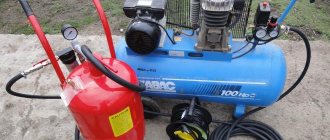
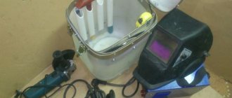
In addition to the reverse, a safety valve must be installed on the compressor. This bypass valve is designed for emergency pressure relief if the pressure switch does not turn off the unit engine. The following photo shows the unloading valve, without which, for safety reasons, the compressor cannot be turned on.
Knocking and rattling in the cylinder and piston group
One of the reasons for compressor failure is a faulty piston group. Recognizing a defect in this system is quite simple. They are usually accompanied by knocking, roaring, grinding and other metallic sounds. If the compressor knocks, then its discharge part, where there are many metal parts that interact with each other, is faulty. Due to their friction and wear, extraneous noise and unpleasant sounds appear.
You should not start with such a breakdown; if possible, you should fix it as soon as you hear the first signs of their manifestation. Main malfunctions if the compressor begins to knock and operate louder than before:
- Broken, worn out bearings, connecting rod bushings
- The bearings on the crankshaft have failed.
- Worn piston, rings, piston pin
- Worn cylinder
- Loose cylinder and head bolts
- A solid particle has entered the cylinder
- The cooling impeller has become loose on the pulley
To repair these breakdowns, in simple cases it is enough to tighten all the bolts and nuts. If the piston, cylinder, crankshaft or connecting rod are worn out, then a comprehensive overhaul is required. When repairing a piston group, you may have to bore the cylinder, if it is badly worn and has external defects, and select a repair piston to new sizes. The following are possible defects in the piston system:
- Changing the diameter of the piston, cylinder
- Distortion of the shape of the cylinder mirror shape
- Risks, scratches, burrs on the cylinder walls
- Cracks in the main working part
- Cracks and broken flanges
During long-term operation, due to wear, marks appear on the cylinder surface, and the inner diameter of the sleeve for the eccentric shaft increases. During repairs, cylinders are restored by pressing sleeves into them. Worn bushings for the eccentric shaft are replaced. This repair is quite difficult to do with your own hands without the necessary tools and equipment. Since the most labor-intensive and critical stage is the restoration of the cylinder. Boring is performed on a vertical boring machine using a special device.
This concerns the cylinder; below we will consider the main malfunctions of the compressor crankcase.
- Cracks in the walls of the crankcase cavities
- Deviations in the size and shape of landing pads
- Warping of seats
- Seats for crankshaft bearings are broken
When these units wear out, they must be replaced with new ones. The hole for the bearings is bored on a horizontal boring machine for a larger diameter of the bearings or for pressing in a bushing, followed by boring the pressed bushing to the required diameter. Repair of a compressor of this complexity should be carried out by qualified specialists.
Below, spare parts “repair kit” for major repairs of the compressor and piston group.
Design and principle of operation
The return design includes the following elements (see figure below):
The return, in addition to the inlet fitting, has a side outlet through which it is connected to the receiver, and 1 thin outlet for connecting a pressure switch.
The check valve works according to the following principle. When the compressor is turned on, air passing through the cylinder suction valve enters the compression chamber, after which it exits through the outlet valve and enters the return inlet fitting (7). When a certain pressure is reached, the valve (6) together with the rubber ring rises and compresses the spring (4). As a result, a passage for air opens. The air moves into the housing cavity (3) and then into the outlet fitting connected to the receiver. After turning off the unit, valve (6), under the influence of a spring and air pressure from the receiver, returns to its place and closes the inlet.
Popular compressors according to customers
Compressor PATRIOT Euro 24-240 on Yandex Market
Compressor Denzel PC 50-260 on Yandex Market
Compressor Metabo Basic 250-24 W on Yandex Market
Compressor Quattro Elementi KM 24-260 on Yandex Market
Compressor Quattro Elementi KM 50-380 on Yandex Market
Check valve 3/8″M for “olive”
Check valve for piston compressors with 3/8" external thread and 1/8" internal threaded connection with a clamping nut and an olive for a plastic tube (Rilsan).
Price on request
Check valve (left) 1/2″M-3/8″M
Check valve for piston compressors Remeza, Aircast, Garage, Balma, Denzel and other manufacturers. Connections 1/2" and 3/8" with external thread. Connections to the pressure switch are made on the left.
Check valve (right) 1/2″M-3/8″M
Check valve for coaxial piston compressors. Connections 1/2" and 3/8" with external thread. Connections to the pressure switch are made on the right (1/8 inch thread for a metal tube).
Bezhetsky ASO Plastic check valve (С4150200130)
Plastic check valve for piston compressors of the Bezhetsk ASO plant. Suitable for compressor models C415, C416, K22 and K33.
Bezhetsky ASO Aluminum check valve (С4150200120)
Aluminum check valve for piston compressors of the Bezhetsk ASO plant. Suitable for compressor models C415, C416, K22 and K33.
ABAC B2800 check valve 1/2″M-3/8″M (9048025)
Check valve for ABAC piston compressors. Two connections 1/2" male and 3/8" clamp nut. The pressure switch is connected to a 1/8 inch thread.
Check valve 1/2″F-3/8″M
Check valve for piston compressors. Connections: 1/2" (internal thread) and 3/8" (external thread). Connection to pressure switch: 1/8 inch (internal thread) for Rilsan tube.
Fubag B4000, B5200, VCF/50 check valve 1/2″M-1/2″M
Check valve for Fubag piston compressors. Two 1/2" male connections. The pressure switch is connected on the left (1/8 inch under the tube).
Check valve (left) 1/2″M-1/2″M
Check valve for Fiac, Remeza and Aircast piston compressors. Two 1/2" male connections. The pressure switch is connected on the left (1/8 inch under Rilsan).
Check valve (right) 1/2″M-1/2″M
Check valve for Fiac, Remeza and Aircast piston compressors. Two 1/2" male connections. The pressure switch is connected on the right (rilsan).
ABAC B3800, B4900 check valve (right) 1/2″M-3/4″M
Check valve for Abac piston compressors. Connections: 1/2" and 3/4" male thread. Connection to the pressure switch: right, 1/8 inch with a clamping nut and an olive for a Rilsan tube.
Check valve 1/2″M-1/2″F
Check valve for piston compressors with 1/2" male thread and 1/2" female thread. Connection to pressure switch: 1/8 inch with clamping nut and olive for Rilsan tube.
Check valve 1/2″M-1/2″M
Check valve for piston compressors General Force, Fubag, Remeza. Two 1/2" male thread connections. Connection to pressure switch: 1/8 inch female thread.
Check valve 1″M-1″M
Check valve for piston compressors General Force, Fubag, Remeza. Two connections with 1 inch male thread. Connection to a 1/8" pressure switch with a clamping nut and an olive for a Rilsan tube.
Check valve 1″M-3/4″M
Check valve for Abac piston compressors. Connections: 3/4" and 1" male thread. Connection to the pressure switch: 1/8 inch (internal thread) with a clamping nut and an olive for a plastic tube (rilsan).
Check valve 1″F-1″M
Check valve for Abac piston compressors. Connections: 1" male and 1" female. Connection to pressure switch: 1/8 inch female thread.
How to make a check valve with your own hands
There are situations when the air compressor return valve has failed, and for some reason it is not possible to buy a new part. In this case, the part can be made by hand.
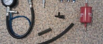
On the Internet you can find quite complex methods for manufacturing this unit using lathes, milling machines and other equipment. But there is still a way to make a simple homemade valve from improvised materials. A drawing of this unit is shown below.
To make a return you will need a metal pipe or tee, a spring, a coupling, a metal threaded plug and a ball.
The air check valve is manufactured as follows.
After this unit is ready, its inlet pipe is connected to the cylinder of the unit, and the second to the receiver.
Source
Compressor valves - what are they?
An air compressor is a unit whose operating principle is based on compressing and supplying air to pneumatic equipment under the required pressure. Such installations are an indispensable element both in everyday life and in industry, being an autonomously functioning technical unit or being included in more complex electrical appliances (for example, climate control or refrigeration equipment). The schematic diagram of any compressor includes a working chamber and a valve system. And since these devices, like any other mechanisms, can break down, you need to know how they are designed, what types of valves there are, how to choose them correctly or make them yourself. More on all this in the material below.
What to pay attention to
Before purchasing a valve, first take into account such a circumstance as the intensity of the existing air flow. In other systems it may be liquid or gas. This circumstance directly affects the startup and error-free operation of the installed valve.
In addition, you need to take into account that the performance coefficients of the air purifying unit are interrelated with the power data of the pumping device, be it a pump or a fan. When choosing a valve, take into account the temperature conditions in the room and the environment in which the device will be installed. The level of environmental pollution is also significant. For example, a unit of the “butterfly” variety, when exposed to a stream of cold air, begins to significantly slow down. This can lead to poor fusion between the duct and the mechanism as a whole. The cost of the valve can fluctuate insignificantly and directly depends on the technical parameters and the company that developed the mechanism.
Types and principles of operation of valve mechanisms
Currently, the most common types of compressors are screw and piston units. At the same time, screw compressors, for example, those produced by the Belarusian plant REMEZA, are widely used in various industries, and piston compressors are used in everyday life. The latter can be found both in garages of car enthusiasts (compressors such as SO-7B, Forte VFL-50, etc.) and in life support systems for fish in aquariums (Resun compressors, etc.), as well as in household pneumatic tools.
Piston compressors are characterized by a simple design and a relatively small number of parts and components. There are many different designs of such compressor units, equipped with special plate valves that regulate the process of suction and injection of air during operation . Depending on the purpose of compressor units (their performance, power and operating pressure), three types of valve mechanisms can be found:
Inlet and exhaust valves
Inlet and outlet valve assemblies play such a role in the operation of compressor equipment.
Unloader and safety valves
Thus, the compressor pumps air into the receiver cycle by cycle until the specified pressure value is reached. This process is monitored by a special pressure switch (pressostat), which controls the operation of the electric motor by turning it on and off depending on the degree of air compression. As a rule, the pressure switch also includes a starting unloading valve. A pressure switch is connected between the output of the compressor head and the check valve (return valve), which is connected to the receiver and holds the compressed air there.
Important! The safety valve is responsible for relieving air pressure. Its functions include: ensuring a smooth start of the compressor and preventing the return of compressed air to the compression chamber after the engine is turned off.
The necessary pneumatic equipment is connected directly to the receiver, which can be additionally equipped with various devices (separators, filters, pressure equalizers, etc.).
Application of safety devices
To ensure safe operation, a safety fitting is a must for any pressure system.
Depending on their purpose, they can be installed in the following places:
- Hot water supply and heating. The safety valve for the heating system is installed on the pipelines after the supply pump. Since hot water is corrosive, the discharge must be directed to a safe location, usually a drain. At high costs, the number of units can reach 2 or more.
- The plumbing fitting for cold water supply is installed in drinking water supply pipelines. The discharge is made directly to the ground.
- Hydraulic system. Hydraulic oils are used as the working fluid. The hydraulic system serves to drive working mechanisms: hydraulic motors, hydraulic cylinders. The safety fitting is installed on pipes, or can be part of a pump or hydraulic distributor. The oil is discharged into the drain line.
- Gas supply pipelines. An increase in pressure in the pipes can lead to an emergency situation - flame separation from the burners, accumulation of excess gas and an explosion in the room. Therefore, the fittings are installed immediately after the pressure regulator, and the discharge is carried out into the atmosphere.
- Air system, compressors. A protective device is installed in the compressor housing and is discharged into the atmosphere.
Compressor safety fitting
Check valve
A check valve (return valve) is a device that allows compressed air to flow in only one direction . Structurally, it is assembled (see figure) in a metal case (item 3), inside of which the following are located:
On a note! The check valve has a branch for connecting it to the receiver and a small branch for connecting a pressure switch.
Operating principle
The reverse action valve works as follows. Passing through the outlet valve of the piston cylinder, the compressed air enters the return pipe through the inlet fitting (pos. 7). Having reached a certain pressure, the air lifts the internal shutter (pos. 6) and passes through the cavity in the housing (pos. 3) into the storage tank of the receiver. When the compressor is turned off, the spring (item 4) returns the internal shutter to its place, blocking the path of air from the receiver back into the piston cylinder.
Varieties
On the domestic market you can find compressors with returns made of three different materials: aluminum, plastic and brass. At the same time, the aluminum part differs from its analogues in its high reliability and durability. It is built inside the air duct that connects the piston cylinder to the receiver, and is capable of operating under high temperature conditions (up to 200°C). Whereas a plastic return line is installed in budget models operating at a low temperature of the working environment. As for valves made of brass, they are widely used. Such return valves are quite reliable and perfectly maintain their performance characteristics in cases where the air temperature during compression does not exceed 140°C.
Toyota Tercel Frankenstein › Logbook › DIY compressor
Because The topic about the compressor has grown to 3 entries; I decided to create an entry covering all aspects of assembling a homemade compressor based on the ZIL-130 head. From idea to implementation. This entry will be updated periodically. Collecting/buying ready-made items is a private matter for everyone. I found a similar compressor in terms of performance and displacement from 15 thousand. Direct drive (small resource). Having thought about it, I started assembling my own.
Now let's look at the following non-obvious thing: why is such a long line from the head to the receiver made? Necessary for easier starting of the compressor. The principle of operation of this unit is simple - air from the compressor head passes through the main line through a check valve into the receiver. The compressor has turned off - the check valve has locked the air in the receiver, the air is standing in the tube. The compressor valves are not so tight and gradually bleed air, thereby the pressure in the tube drops. The motor needs a few moments to enter operating mode, and these few moments are provided by the tube and check valve.
Secondly, to reduce condensation at the outlet of the compressor, it is recommended to introduce air further from the outlet.
So, having understood the design of the compressor, and having understood some aspects, it was decided to sculpt a design that is not difficult to repeat.
1) Receiver
- a household propane cylinder 40-50 liters. (Before welding, degass, I am not responsible for your rash actions.) The following are welded into the body of the receiver: a piece of water pipe for a 1/2-inch back pressure valve, a piece of water pipe for a condensate drain tap, M12 nut for the emergency pressure valve (previously it was a valve for a 1/4 thread, I cut it with a die for M12). The air exits through the neck of the cylinder - a 3/4 inch bend, screwed into the cylinder (the cylinder has a 3/4 k thread (conical), screwed in without problems.
2) Electric motor
(for a head from a zil, the optimal power is 2.2 kW 220 Volts (in the absence of a 220 volt motor, a 380 will do, but take into account the percentage drop in power of about 30%). The gear ratio will be written separately. My version of the motor:
3) Protective grille
(I haven’t worked on this aspect yet, I’m thinking of taking it from an old refrigerator)
4) Belt
1150 mm long, picked up at a GAZ auto parts store, installed on a gazelle (I don’t know where).
5) Check valve
, I installed from water: internal threads 1/2 inch on both sides)
 Pressostat
(at the moment this unit is not on my compressor). The air outlet is carried out through the BKO 50 oxygen reducer, protection against rupture is provided by the air release valve (at the moment I have temporarily set it to 6 bar.
9) Dump valve
condensate (1/2 inch tap)
Auxiliary nodes:
1)
Frame
: made of a 20x20mm profile, 56 centimeters long, 32 centimeters wide, with 6 racks, rack height 9 centimeters. The frame was designed for a 1150 mm belt.
Source
Safety valve
The relief valve (another name is safety) valve serves for emergency release of pressure and is the final device that protects the pneumatic equipment connected to the compressor from damage.
Attention! It is not recommended to operate the compressor without a safety valve.
Experts also include the following types of relief valve:
Despite minor design differences, their operating principle is identical to a safety valve.
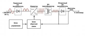
Operating principle of the safety valve
Compressor equipment that is not intended for use in industrial environments is equipped with spring-loaded safety valves. When such a compressor operates in normal mode, it is closed (see diagram). In this case, the air pressure on its plate is balanced by a calibrated spring, which prevents the locking mechanism from opening. If the pressure suddenly increases above the set value, the pressing force of the plate against the nozzle decreases and the valve begins to open. This releases excess air, after which the locking mechanism can return to its place.
Important! If the relief valve does not return to its place for a long time, then the compressor must be turned off and the cause that caused the unauthorized increase in pressure must be eliminated
Bypass valve
The bypass (or overflow) valve maintains the pressure of the working medium at a given level. To do this, through the existing branch there is a constant, and not one-time or periodic, as in a safety valve, removal of an excess amount of the working medium (compressed air, gas, liquid), which ensures pressure stability in the system. Such valves are used, for example, in turbochargers installed on automobile internal combustion engines.
Unloading valve
The unloading valve ensures the release of compressed air remaining in the manifold between the piston block and the return line when the compressor stops. In this case, the pressure at the compressor outlet is reduced to atmospheric pressure. In general, the presence of an unloading valve makes it possible to:
In addition, the unloading valve is used in cases where it is not possible to turn off the mechanical drive of the connected pneumatic equipment . Install it at the compressor outlet in front of the return line.
So, the more productive and powerful the compressor equipment, the more complex the valve system. The simplest check valve for use in a household low-pressure compressor can be made by yourself. But for the installation to work correctly, it is recommended to purchase a factory-made part.
The compressor gets very hot
If the compressor gets very hot, this indicates some kind of malfunction. There may be several reasons for overheating. Starting with a simple one, the air flow to the cylinder and crankcase is blocked. Check whether the impeller is blocked by foreign objects.
One of the main reasons for an overheating compressor is insufficient oil level. The working units wear out, high friction is created and as a result it gets very hot. If such work continues, the equipment will quickly fail. Check the oil level; if it is not enough, you need to add it to the required level.
Valve malfunctions due to carbonation or loosening. There may also be clogged air passages.
Look at the pressure level, perhaps the automation has broken down and the compressor is “threshing” to high pressure, this causes overheating. The safety valve may need to be repaired or replaced.
Try to locate the compressor in a cool, spacious place, especially during the hot season. Whatever cooling it has, it will heat up much less, which will affect its positive and durable operation.” Also, do not forget that the colder the air, the less moisture and oil impurities it contains.
Safety check valve for a compressor: types, design, DIY production
In order to ensure the correct operation of compressor units used almost everywhere today, a number of additional technical devices are used, one of which is a check valve for the compressor. Such a valve, which is equipped with the vast majority of compressor units today, also protects them from premature failure and ensures smooth starting.
Check valve on compressor
Purpose, design features and scope of application
A check valve installed at the outlet of the compressor head allows compressed air to pass in only one direction - to the receiver or any other reservoir. Thus, this valve prevents the return of compressed air located in the receiver or other elements of the pneumatic system back to the compressor. The greatest risk of compressed air returning from the pneumatic system to the inside of the compressor is during breaks in the operation of the device (if the compressor discharge valves do not fit tightly to the seats), as well as at the time of its startup.
Main varieties
Check valve systems, depending on their design, can be:
Direct type check valve for high pressure stations
The material of manufacture may also vary, depending on what environments such a device will come into contact with during operation. In particular, it can be either metal alloys of various types or plastic.
Depending on the type of shut-off element used, check valves can be:
The last three types of devices are used for installation in ventilation systems. Among check valves and safety valves installed on compressors, ball-type devices are the most popular, since they are less critical to contaminants present in the working environment.
Check valves with cone (a), flat (b) and spherical (c) shut-off elements
Among the most modern valve systems, it is worth noting electromagnetic type devices, in which the movement of the valve is controlled not by a spring, but by an electromagnet. Meanwhile, due to the rather high cost and not too much reliability, such devices are not very popular, inferior to cheaper and time-tested spring analogues.
Main types
Check valve mechanisms are divided into:
- straight view;
- corner;
- spring;
- ball;
- installed using flanges;
- casement;
- installed by soldering;
- produced for beading.
Still, there is one main drawback: such an air valve is placed on the absorption tank and has a very negative effect on the combined cooling capacity.
In any case, regardless of the type and intended purpose of the mechanism, you must carefully ensure that foreign particles do not fall on the clearance part. Otherwise, even when in the closed position, the shut-off valve will not be able to fully guarantee its functionality.
In order to install any of them (meaning a type of valve), you must take into account the setup and configuration of the system. In addition, these installations are distinguished based on the specifics of their shape (square and round) and the product from which they are made. Each of the products used has its own specifics. Based on this, many mechanisms are equipped with units made using plastic, and some with metal units.
Nowadays the most popular type is the plastic valve. The throughput capacity of this mechanism is up to 6 m/s. This value is achieved due to the noiselessness when switching on and off the operating components. Such a modification of the unit can operate either with the help of a valve supplied for exhaust, or independently. It should be noted that this variety is not very popular among buyers due to being replaced by more economical analogues. Today you can purchase the most popular type of valve for compressors - the so-called “butterfly”.
These devices are made using metal, and the top is treated with a thin galvanized layer. The mechanism is equipped with two rotating blades, which are attached to the central axis. When the exhaust manifold is disconnected, the parts become short-circuited. The butterfly valve is sold in several versions, the dimensions of which range from 31 cm.