Rollers are versatile equipment that allows you to effectively cope with sheet bending operations. Making rollers with your own hands is not so difficult, but to do this you need to first become familiar with the serial models, their design and principle of operation.
Three-roll hand rolls are the most suitable design for do-it-yourself production.
Design Features
Rollers (also called sheet bending machines) allow controlled plastic deformation of sheets made of metal. Operating on the rolling principle, such a device is equipped with several shafts, which, when a metal sheet or pipe passes between them, changes their configuration. Serial models of such sheet bending equipment and homemade rollers work on the same principle and, accordingly, have a similar design. Let's look at the main elements of the machine.
Design of manual three-roll rollers
Bed-base
This is a load-bearing element that ensures the stability of the rollers, as well as the correct relative position of all their components.
Two vertical support posts
In their bearing units, shafts are installed, of which there can be only two (two-roll machine), three (three-roll machine) or even four. In the design of most rollers equipped with three working bodies, the two lower rollers can change their position only in the horizontal plane, and the third, a thrust roller located on top, is also adjustable in height. In addition, the upper roller for removing the finished part is equipped with a quick tipping mechanism.
Mechanism for lifting the upper pressure shaft
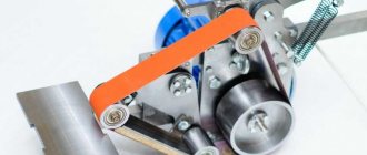
Rolls
During the processing of a sheet blank, the rolls must rotate, for which any rolling machine is equipped with a drive mechanism, which can be chain or gear. The operation scheme of such rollers is such that only the lower rollers are driven into rotation, and the upper one, tightly pressed against the surface of the workpiece, rotates under the influence of friction forces.
Roll operation diagram
Rollers can be equipped with various types of drives. Thus, depending on this parameter, rolling devices of the following categories are distinguished.
Manual
These are the simplest rollers, which are most often made by hand. To drive such devices, chain and gear drives can be used, the parameters of which should be selected depending on the characteristics of the material being processed. Hand rollers, taking into account the fact that significant physical effort is required to operate them, are used primarily for processing small workpieces.
Electrically driven
In terms of their performance, such rollers belong to the average category. Electrically driven three-roll rollers, due to the sufficiently high power of the drive mechanism, make it possible to process workpieces of considerable size.
Electromechanical rollers are often a modification of a manual machine to which a motor and control panel have been added.
Hydraulically driven.
This is the most powerful of all rolling equipment on the market today. Due to the fact that the hydraulic drive with which such rollers are equipped allows their working bodies to act on the workpiece with great force, such a device can effectively process metal sheets of even very significant thickness.
Among industrial hydraulic rollers there are even such giants
The quality of processing performed on rollers is primarily influenced by the characteristics of the rollers. Since the rolls experience significant mechanical loads during operation, high-strength tool steel is used for their manufacture. In addition to the mechanical impact, when processing sheet blanks of considerable thickness, which are preheated to give them greater plasticity, the rollers also experience thermal impact. It should be noted that such an impact, which can be very significant, has a rather negative impact on the operational characteristics of the rolls.
The quality of processing performed on rollers can be improved by equipping them with CNC systems, the tasks of which include coordinating all operating modes of the machine (the relative position of the rollers, the amount of pressure exerted on the workpiece, etc.).
IB2222 Control panel for three-roll plate bending machine
Control panel for three-roll plate bending machine IB2222
IB2222 List of roller controls
- General stop
- Control circuit switch
- Main drive rotation direction switch
- * Release button - forward
- * Button for turning on the removal mechanism - back
- Button for lifting the folding support
- Knob lowering buttons
- Button for switching the shell support mechanism up
- Button for switching the mechanism to support the shell down
- Rear side roller up button
- Rear side roller down button
- Front side roller up button
- Front side roller down button
- Signal lamp "Network"
- Signal lamp “Main drive is on”
* For machines with mechanization means
Note: On sheet bending machines, the control panel can be built into the main drive guard (IB2213, IB2216 machines) or be remote - attached to the knee switch brackets (IB2219, IB2220, IB2222 machines).
Main technical parameters
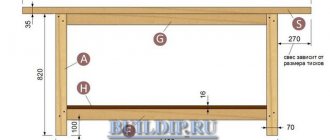
How to make a sheet bending machine with your own hands? To do this, it is necessary not only to develop drawings of such a device, but also to determine its technical characteristics. It is best to take the design of a serial model as a basis and independently adapt it to your own needs.
Assembly drawing of a factory-made three-roller machine (click to enlarge)
Considering the fact that you are going to install your rollers in a certain room, you should immediately decide on their dimensions. This parameter, which directly depends on the length of the installed shafts, will determine what width of sheet blanks you can process on a device made by yourself. When deciding on the size of hand rollers, you should also take into account the fact that processing sheet blanks with a width of more than 1.2 meters using them will be quite difficult physically. The weight of a homemade machine will affect the ability to move it around the room and transport it.
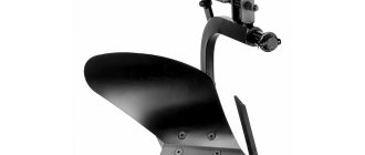
Drive shaft. Drawing (click to enlarge)
Folding shaft. Drawing (click to enlarge)
Pressing shaft. Drawing (click to enlarge)
Drawing of three-roll plate bending rollers with electric drive (click to enlarge)
In addition to the dimensions and weight of future rollers, it is necessary to determine the following characteristics of such equipment:
- the diameter of the rolls - the main working parts of the device (this parameter, which is quite important, will determine the maximum radius with which you can bend the metal sheets being processed);
- the maximum distance at which the upper thrust roll can be located from the lower ones;
- the maximum distance to which the lower rollers can move apart;
- the speed at which the processed sheet material can move between the rolls.
Studying the technical parameters of factory models will help you decide on the size and design of the machine.
An important parameter that you should pay special attention to when developing a drawing of future rollers is the rigidity of their design. When processing metal sheets, significant mechanical loads are experienced not only by the rolls, but also by all other components - bed, drive mechanism, etc. That is why the choice of the roller operation scheme, as well as the selection of materials for its implementation, should be done with particular care.
Most often they are used for the manufacture of 3-roll rollers, since an increase in the number of working parts of such low-power manual devices leads to an increase in the level of load exerted on its drive mechanism.
Information about the manufacturer of the three-roll plate bending machine IB2222
The manufacturer of the three-roll sheet bending machine IB2222 is the Slavgorod plant of forging and pressing equipment KPO named after the 8th anniversary of October .
The developer of the IB2222 sheet bending machine is Azov Special Design Moscow Bureau of Forging Equipment and Automatic Lines, SKB Co.
Machine tools produced by the Slavgorod press-forging equipment plant KPO
- I2222
- three-roll sheet bending machine 2000 x 16.0 - IB2220
- three-roll sheet bending machine 2000 x 10.0 - IB2222
- three-roll sheet bending machine 2000 x 16.0 - IB2222V
- three-roll sheet bending machine 2000 x 16.0
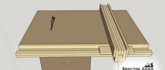
IB2222 Setting up a machine for bending conical shells
Setting up the IB2222 machine for bending conical shells
To bend conical shells, the upper roller is placed in an inclined position at an angle ε to the horizontal. Angle ε and the amount of movement of the left support of the upper roll Δh left. are obtained from the following relationships between the cone angle and the required bending radii (see Fig. 28).
The angle at the top of the conical shells (maximum) is for machines:
- IB2213 - 30°
- IB2220, IB2216, IB2222 - 20°
- IB2219 — 15°
Install the upper roller in the position for bending conical shells in the following sequence:
- loosen the lower spline nuts on the tilt support screw
- Using the front link, set the upper roller to the desired position while simultaneously turning the screw into the glass by rotating the coupling manually. Control of movement along the ruler on the stand
- tighten the lower spline nuts with slight force. Open the folding support and tighten the top nuts. Tighten the lower nuts, close the support
- Use nuts to secure the upper roller console rod, while adjusting the free tilting of the left support
- adjust the position of the limit switch using the grooves in the limit switch bracket and the stop bar in the tilt support drive
- Place a device for bending conical shells on the neck of the upper roll with the folding support removed. When putting on the folding support, the shank of the device stop must enter the device by rotating around the landing neck - the roll.
- Return the roller to the horizontal position in the reverse order. When bending conical shells, the sheet is installed in such a way that the concave edge of the smaller diameter of the truncated cone workpiece is adjacent to the stop of the device for bending conical shells.
- D1 = 270 (top roll diameter)
- D2 = 260 (diameter of side rolls)
- * d1 = 324 (setup diameter for pipe bending for the upper roll)
- * d2 = 314 (diameter of setting for bending pipes for side rolls)
- * d3 = 360 (diameter of setup for bending long products)
- R = 420
Where *dimensions for reference:
Maximum dimensions of long products and Rmin minimum bending radius:
- pipe bending tools . Maximum pipe diameter - Ø32; 45, Rmin = 400 mm
- Setting up a tool for bending a double angle with the flange facing outwards. Maximum dimensions of the corner - 50x50x5, Rmin = 450 mm
- Setting up a tool for bending a channel with the flange facing outwards. Maximum channel size - No. 12, Rmin = 400 mm
- square bending tool . Maximum square dimensions - 50x50, Rmin = 300 mm
- Setting up a tool for bending strips on edge. Maximum strip dimensions - 36x60, Rmin = 400 mm