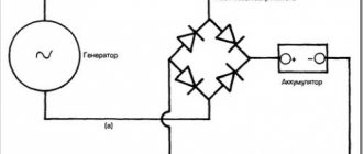
The main task of welding arc power sources is to produce an electric current with characteristics suitable for welding work by converting the industrial frequency current.
We will not be able to use voltage directly from the network, due to the fact that the current in our network is variable and small in magnitude, and the voltage is high. Often a direct current with a choice of polarity is required. For such purposes, a power source for the welding arc is needed.
Primary requirements
Today, all power supplies must meet the following basic requirements:
- have smooth adjustment of welding modes throughout the entire range;
- have available instruments for monitoring welding modes;
- ensure stable arc burning;
- have high dynamic characteristics;
- comply with basic electrical safety requirements.
The presence of smooth adjustment and control devices ensures precise adjustment of the required welding modes.
The dynamic properties of the welding machine are determined by the recovery time of the open circuit voltage after a short circuit during the welding process. The faster the voltage is restored, the better its dynamic characteristics. Recovery should not exceed 0.05s.
To increase the stability of the arc, oscillators can additionally be used. They convert low voltage industrial frequency into pulses of high voltage and high frequency. The application of these pulses to the arc gap increases the stability of the arc.
Classification
The modern classification of welding arc power sources includes several main points. Among the main differences are:
- By the type of welding current - transformers work with alternating current, and rectifiers, converters and inverters work with direct current;
- According to the number of connected posts - single and multi-post;
- By purpose - power sources for automatic, manual and semi-automatic, which can be carried out in a protective gas environment, submerged arc welding, as well as in the form of plasma and electro-slag welding;
- According to the principle of operation - welding transformers (with a separate choke, normal magnetic dissipation, on a common or separate core, with artificially increased dissipation, a movable shunt and windings), converters (with a series demagnetizing winding and with a movable shunt, together with a movable winding, magnetized in parallel and demagnetizing series winding, demagnetizing series winding), units (internal combustion generator), rectifier - (silicon or selenium valve, single or multi-position, with a rigid or falling characteristic);
- By the nature of the drive - with an independent or electric drive;
- According to the method of installation and installation - mobile and stationary.
Classification of welding arc power sources
Requirements
There are many types of sources and each of them has its own parameters. When choosing, you should focus on models and types that meet modern requirements. The requirements for welding arc power sources are as follows:
- It is desirable to have smooth adjustment of parameter values throughout the entire range;
- The device must have the highest possible dynamic characteristics, for example, the transient process time should not be higher than 0.05 s);
- It is desirable that the inverter power supply not only has functions that improve quality, but also improves the organization of this work;
- You should pay attention to the presence of devices that monitor the accuracy of adherence to the regime;
- The open-circuit voltage in DC inverters should be no more than 90 V, and in AC sources it should not exceed 80 V;
- In modern models there should be stabilization of the welding mode, which will make the value of the parameters constant, regardless of fluctuations in the network;
- If argon arc welding with a tungsten electrode is used, then special sources should be used that can provide a smooth increase in current when the arc is ignited, a pulsed-arc process, as well as a decrease in the current level during crater filling.
Choosing a power source?
If you choose AC or DC welding arc power sources, then first of all you should pay attention to what maximum current it can provide. This determines the range of its use. The higher the maximum amperage, the thicker metals it can weld.
"Important!
Particularly powerful devices can often only be connected to a three-phase network, so they are not always suitable for domestic use.”
You also need to pay attention to the quality of the cooling system, since prolonged operation can cause severe overheating. In addition, you should choose sources that have additional modes that make welding easier and create greater stability.
For modern use, models with precise parameter adjustment are better suited. This may be a digital display or a knob with a dial and dial. The ability to control several parameters at the same time will also be a useful addition.
Classification of welding arc power sources
Welding arc power sources have many classifications, namely:
- according to supply voltage:
- single-phase (220V);
- three-phase (380V).
- according to external static characteristics:
- falling;
- hard;
- bayonet
- by the number of posts fed:
- single-post;
- multi-post.
- by type of current:
- variable;
- constant.
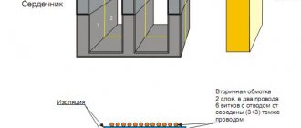
Transformer
Today, this is the simplest power source for a welding arc that produces only alternating current at the output.
Smooth control of the welding current is carried out by changing the gap in the choke coil or between the windings. Stepped - by switching the number of turns of the primary and secondary windings.
Transformers are very simple, which makes it possible to make it yourself. Currently, transformers are not relevant. This is due to the fact that direct current does not provide a stable arc, and its use when welding stainless steels is impossible.
Classification and designation of power supplies
welder
Arc power sources are classified according to the following criteria: type of current—DC and AC sources for general industrial purposes; the number of simultaneously connected welding stations - single-station and multi-station; intended purpose - for sources for manual arc welding with coated electrodes; automatic and mechanized submerged arc welding; welding in shielding gases; electroslag welding; plasma welding and cutting; sources for special purposes (for three-phase arc welding, pulsed arc welding, etc.); principle of operation and design; specialized power supplies in installations.
Letters and numbers are used to designate power supplies. It consists of two parts, separated by a hyphen: the first letter indicates the type of product (T - transformer, V - rectifier, G - generator, U - installation); the second letter is the type of welding (D - arc, P - plasma, Ш - electroslag, T - three-phase arc); the third letter is the welding method (F - submerged arc, G - in shielding gases, U - universal sources for several welding methods); the absence of a letter means manual welding with stick electrodes; the fourth letter is a further explanation of the purpose of the source (M - for multi-station welding, I - for pulse welding); one or two pifr. after the hyphen - the rated current of the source (rounded in hundreds of A); the next two digits (for example, 02) are the product registration number; the next letter and number are the climate version (U or T) and the placement category (2; 3 or 4).
As an example, the designations of two power sources and their interpretation are given:
VDGM 1602UZ—multi-station rectifier for manual welding in shielding gases; current strength - 1600 A; product registration number - 02; climatic version - U; accommodation category - 3.
TD-502 - transformer for single-station manual arc welding with stick electrodes; current strength - 500 A; product registration number - 02.
AC Power Supplies
These power sources include welding transformers designed for one station and used for manual arc welding with stick electrodes and for mechanized welding
Submerged as well / 2 J
Three-phase power sources 9 o. Welding transformers are divided into two groups: with normal magnetic leakage and a separate reactive winding; with increased reactive scattering.
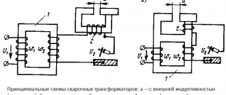
Single-phase welding transformers with normal magnetic leakage and separate reactive winding. In transformers of this type (Fig. 5.3), the inductor winding is connected in series to the welding circuit. The falling characteristic is created by the self-induction emf that occurs in the inductor winding. The strength of the welding current is smoothly adjusted by changing the gap between the moving and fixed parts of the choke. At 6 = 0, the current strength is minimal, since the magnetic flux in the inductor core and the self-induction emf have maximum values. At maximum gap b the current is maximum.
According to this scheme, the industry previously produced welding transformers STE-24u, STE-34u, STN-350, STN-500, STN-500-1, STN-700. Currently, transformers TSD-500-1, TSD-1000-4, TSD-2000-2 are produced, intended for powering automatic installations. The technical characteristics of these transformers are given in table. 5.1.
Transformer type /Characteristics TSD-500-1 TSD-1000-4 TSD-2000-2 Open circuit voltage Ux.X, V 80 71 79 Duration of operation PR, % 60 Rated welding current /n, A 500 1000 2000 Rated power ...
Welding classification. Types of arc welding
Welding classification. According to GOST 19521-74, metal welding is classified according to physical, technical and technological characteristics. According to physical characteristics (form of input energy, presence of pressure and type of instrument that carries energy), all types...
TECHNOLOGICAL PROCESS OF MANUFACTURING WELDED STRUCTURES
Welding is the main technological process of manufacturing all types of metal structures. The use of welded joints instead of riveted or bolted ones makes it possible to reduce weight (by 20...30%), the complexity of manufacturing (by 20...30%) ...
msd.com.ua
Rectifier
Converts alternating current of industrial frequency into direct current, necessary for welding.
Rectifiers are single-phase and three-phase, stationary or mobile. Have the ability to change the current-voltage characteristic to hard or falling, as well as polarity when welding.
Smooth regulation of the welding current is carried out by the control unit, and stepwise regulation by switching the windings.
Their widespread use in production speaks of their versatility and productivity. High efficiency and the ability to be used when welding various metals make them one of the most popular power sources.
contents .. 1 2 3 6 ..3.1.3
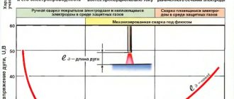
Current-voltage characteristic of the arc (VACH)
This dependence relates the arc voltage Ug to the arc current Ig at a constant arc length (Fig. 3.2. (for RDS)
Point A marks the open circuit voltage Uxx of the power supply. After the arc is ignited, the voltage drops to a stable position (I zone of unstable arc burning). A further increase in current does not cause a change in Ug (zone II). This zone corresponds to the average current densities during RDS (zone II).
A further increase in Ig leads to an increase in arc voltage (zone III). This section of the VAC corresponds to high current densities during RDS and, especially, with automatic DS methods, where thin electrode wire and relatively high currents are usually used.
Rice. 3.2. Current-voltage characteristics of arcs for manual arc welding (MAW), arc length lg1 is greater than arc length lg2.
When the arc length lg of the VAHD changes, the arc voltage Ug changes, but the nature of the dependence Ug = f (Ig) in sections I, II, III remains the same.
3.1.4 Power sources (PS) for arc welding.
Power sources can be direct current, alternating current (f =50Hz), pulsed current sources, inverter (high frequency, f =1-20Hz) power sources.
3.1.5 Requirements for individual entrepreneurs
1. Safe open circuit voltage Uxx. Unfortunately, this requirement is not met. For safety reasons, the safe voltage is set to 36V. For stable arc burning, a power supply with Uxx exceeding the safe voltage is required (argon arc welding - Uxx > 40V, RDS - Uxx = 60...80V). The voltage Uxx IP is influenced by the electric arc intensity Eg (V/cm). The more Eg, the more Uxx of the power source.
2. Smooth control of the welding arc current. In industrial individual entrepreneurs this requirement is met. Typically, power supplies also have stepwise current regulation (low currents, high currents).
3. For certain DS methods, power supplies with appropriate external (load) characteristics are required.
The external characteristic of the source (ECI) is the dependence of the voltage at the terminals of the power source and current on the load resistance; the load is the arc resistance, which depends on the arc length. Each power source has a VCI spectrum over the entire arc current control range. The graph (Fig. 3.3) shows one VCI for power sources that are used for various arc welding methods (RDS, ADS).
Rice. 3.3. VCI of various power sources.
1- vertical VHI; 2- steeply falling VHI; 3- flat-sloping VCI; 4- horizontal (rigid) VCI; 5-increasing VHI.
IP with external characteristics 1,2 are used for RDS, IP with VHI 3,4,5 are used for automatic DS methods with self-regulation of arc length.
3.1.6 AC power sources for RDS (welding transformers).
Power supplies for RDS, including welding transformers, have increased internal resistance, which limits the short circuit current (Isc) throughout the entire arc current control range (Fig. 3.4).
Fig.4. VHI for IP RDS.
The operating mode (Ig, Ug) is determined by the point of intersection of the external characteristic of the source (VHI) with the current-voltage characteristic of the arc (VACH).
For such IP, when the arc length changes (from lg1 to lg2), the arc current changes by a small amount DIg, so vibrations of the welder’s hand do not have a significant effect on the stability of metal melting.
Welding transformer with a separate choke (Fig. 2.5).
Fig.2.5. Welding transformer with separate choke.
The falling characteristics in such a power supply are created due to the inclusion of an arc inductor winding with inductive reactance in the power circuit
Rldr=2p f Ldr,
where f is the frequency of alternating current (50Hz), Ldr is the inductance of the inductor, depending on the size of the gap d, which changes when the moving link of the inductor core moves.
For this power supply:
With a short circuit Rg=0, the resistance of thick copper wires can be neglected, then
For d max we get L drmin and Ikzmax, for d=0 we get Ldrmax and Ikzmin.
Step control of Is can be achieved by connecting a different number of turns of the choke coil to the arc power circuit (Ldr also depends on the number of turns of the coil).
Welding transformer with magnetic shunt.
This transformer (Fig. 3.6) was developed by Academician Nikitin in the 20s. It has very good characteristics, ensuring a stable process of manual arc welding. The main disadvantage is the large mass of the iron core.
The transformer has an increased internal inductive reactance, which limits the short-circuit current, i.e. it has steeply falling VCI.
Adjustment of the short circuit current is ensured by extending the magnetic shunt from the transformer core circuit.
Fig.3.6. Welding transformer with magnetic shunt.
If a magnetic shunt (MS) is completely inserted into the window of the iron core of the transformer, then the magnetic flux F1, created by the current in the primary winding in rod 1, is shunted by the MS. The magnetic flux F2 in rod 2 will be minimal, and accordingly, Ikz will be min.
With the complete removal of the MS from the core window, Ф2 = Ф1 and, accordingly, we obtain Iкзmax.
In case of short circuit
L ext depends on the position of the magnetic shunt in the core window.
Welding transformer with movable secondary windings.
Currently, the industry produces mainly such IP for alternating current arc welding (Fig. 7). Compared to the transformers discussed above, these transformers have a smaller iron core mass.
Fig.7. Welding transformer with movable secondary windings.
The internal resistance Rl of such a transformer depends on the distance l between the primary and secondary windings. At l max, the secondary winding is affected only by the magnetic flux Fs, which is closed through the iron core, and we obtain Is min.
Ikz min = f (Fs)
As l decreases, the secondary winding is affected by the magnetic leakage flux Фр, which closes around the primary winding through the air. When l = 0 we obtain Ikz max = f (Fr max + Fs).
3.1.7 Direct current sources for arc welding.
In some cases, the use of cheaper alternating current DC is impossible or difficult. In this case, direct current is used for DC.
DC welding has the following advantages:
n the possibility of using direct or reverse arc polarity, which allows you to regulate the heating of the welded product, because Ta > Tk;
n high arc stability, which makes it possible to maintain the arc at low current and weld thin-walled structures.
The disadvantages of these IP include higher complexity and cost than AC IP, as well as the fact that the DC arc is susceptible to the influence of extraneous magnetic fields (magnetic blast), which sometimes makes welding difficult.
Welding generators and welding rectifiers are used as DC power supplies. A welding generator driven by an internal combustion engine can operate in places where there is no electrical network (in the field). For manual arc welding, welding generators with increased internal resistance are used, i.e. with steeply falling external characteristics. Like standard generators, welding generators are manufactured according to different schemes (generator with an independent excitation winding, self-excited generator, generator with a transverse magnetic field, etc.).
As an example, consider a self-excited welding generator (Fig. 8).
Fig.8. Self-excited welding generator.
Unlike standard generators, in welding generators for internal resistance, the magnetic fluxes of the series winding OP and armature (Fp and Fya) are directed towards the magnetic flux Fv of the excitation winding OB. When interacting, these flows are subtracted.
At idle, the electromotive force of the generator is Ug = kn Fv, where n is the armature revolutions; k is a coefficient depending on the design of the anchor.
,
where Iв is the current in the excitation winding; Wв - number of turns in OB; åRm is the sum of the magnetic resistance to the fluxes in the field winding.
When the arc is burning
,
where Iп is the current of the OP winding; Wп - number of turns of the OP winding;
Iа — current in the generator armature winding (Iа = Iп);
Wя is the number of turns of the armature winding connected in series with the OP winding with carbon brushes through the armature commutator.
During a short circuit, the voltage at the generator terminals drops to almost zero (the voltage drop across the thick copper wires of the windings can be neglected). Then at Ug = 0 short circuit current
Isk is regulated by changing Iv, the resistance of the rheostat R (smooth adjustment), stepwise adjustment of Ik is performed by changing the number of turns Wp with switch S.
contents .. 1 2 3 6 ..
Converter
The work of the converter is to convert the alternating current of the network into the mechanical energy of an electric motor. As a result of rotation of the generator shaft, mechanical energy is converted into direct current electrical energy.
A big advantage is the insensitivity to voltage drops, so the output produces a direct current with a stable current-voltage characteristic.
Due to their large mass, they are almost always made stationary. The downside is low efficiency and high wear on moving parts.
At the moment, converters have lost their relevance.
Inverter
The principle of operation of these devices is to convert alternating current from the network into direct current. Next, the direct current is again converted into alternating current, but only at high frequency. After this, alternating current is supplied to a high-frequency welding transformer, which lowers the voltage and converts alternating current to direct current.
Inverters are one of the most popular welding arc power sources today. This is due to a number of advantages:
- constant current with smooth regulation;
- affordable price;
- stable burning of the welding arc and its easy ignition;
- small overall dimensions;
- low power consumption
- light weight.
All this makes inverter power supplies indispensable in everyday life, as well as in large enterprises.
Current-voltage characteristics of welding current sources
VDM-6301
Static characteristics of welding power sources
The current-voltage characteristic of an arc is the relationship between voltage and arc current in a steady-state (static) mode.
The voltage in the welding process depends on the length of the arc; the longer the welding arc, the higher the voltage. The steeper the current-voltage characteristic of the welding current source, the less the influence of the length of the welding arc on the welding current. The static current-voltage characteristic of the arc shows the relationship between the steady-state values of the current and voltage of the arc at a constant arc length.
In manual welding, the static characteristic of the welding arc is usually rigid, and the deviation of the current when changing the arc length depends only on the type of external characteristic of the power source.
The external current-voltage characteristic is the dependence Ui = f(Id), which in general form is obtained from an analysis of the circuit diagram of the “source-arc” energy system
The source can operate in one of three modes: idle, load, short circuit.
When idling, the arc does not burn, there is no current. In this case, the source voltage is called open circuit voltage, the maximum source voltage
When there is a load along the arc and the source, a current flows, a voltage lower than during no-load, by the amount of the voltage drop inside the source.
Experimentally, the external characteristic of the source is measured by measuring voltage and current with a smooth change in load resistance, while the arc is usually simulated by a linear active resistance-ballast rheostat.
The graphical representation of the resulting dependence of voltage on current is the external current-voltage characteristic of the source. As the load resistance decreases, the current increases and the source voltage decreases. Thus, in the general case, the external current-voltage characteristic of the source is incident.
Let us estimate the efficiency of current sources and their operating modes. Obviously, to increase the efficiency, i.e. To improve energy efficiency, the internal resistance of the source should be reduced. The highest coefficient, close to unity, is obtained at the lowest welding currents, when the resistance approaches infinity.
Dynamic properties of the welding power source
Dynamic properties are characterized by the voltage recovery time from the moment of a short circuit to the operating value when the arc burns. The faster the voltage is restored, the better the dynamic properties of the current source
Processes in a real source-arc system are extremely fast. Steady state intervals last no more than a few seconds. Transient processes arise from influence on the part of the welder and cause a transition from idle mode to short circuit and then to load mode, a smooth decrease in current as the arc lengthens at the end of welding. Processes can be caused by external influences, such as fluctuations in network voltage, or internal ones, arising, for example, during droplet transfer of electrode metal. Pulses can be generated by a source to control electrode metal transfer and weld formation. But more often, the pulsating nature of the supply voltage is considered a disadvantage; for example, three-phase welding rectifiers and especially single-phase rectifiers without a smoothing filter have such voltage. In the continuous transient process mode, welding is carried out with an alternating current arc. In this regard, the question arises about the validity of the concept of a static current-voltage characteristic in relation to sources of alternating and rectified unsmoothed current. However, it has been proven that if the static characteristic of such a source is constructed for effective (or average) values of current and voltage, then almost all the conclusions obtained for a direct current source apply to it with a certain accuracy.
In the simplest sources, the required level of dynamic properties was ensured by selecting such source parameters as open circuit voltage, internal resistance, and the inductance of the welding circuit.
Feedback sources are also being developed. In them, using current and voltage sensors, the actual value of the characteristics of the transient process (peak current, short circuit duration, etc.) is monitored, and after comparing them with the regulated values, the control system acts on the source, bringing these characteristics back to normal. This principle of controlling dynamic properties is called compensatory.
Of course, several management principles can be combined in a particular source.
Checking the welding properties of power sources
To test power sources for manual arc welding, differentiated and cumulative methods are used.
The differentiated method is used to evaluate:
- initial arc ignition;
- stability of the welding process;
- metal splashing;
- quality of seam formation;
- arc elasticity.
The cumulative test method is used in comparative tests to evaluate the welding properties as a whole according to a single generalized indicator, while the comparison is carried out with two standard power sources with previously known and different values of welding properties.
To test power sources for automatic and semi-automatic welding in carbon dioxide, a differentiated method is used to evaluate:
- reliability of establishing the welding process;
- metal loss;
- quality of seam formation.
A differentiated method for assessing the welding properties of manual arc welding power sources is used during periodic, standard, preliminary and acceptance tests, and carbon dioxide welding power sources are also used during comparative tests.
During preliminary, acceptance and comparative tests, along with an assessment of the welding properties of the sources, an assessment of the welding properties of a serial source for the same purpose is carried out.
If you find an error, please select a piece of text and press Ctrl+Enter.