Published
08.11.2019 |
Author: kmveg 0
In physics there is such a thing as direct and alternating current. In fact, these two concepts are not entirely correct, but this is how it happened historically. Direct current is the directed movement of particles that do not change either in direction or in magnitude, regardless of time.
Along with this, there is also alternating current, in a particular case the direction of which is constant, but its magnitude changes. In order to straighten it, a current rectifier is used.
Using such a device, a unidirectional pulsating current is obtained. In fact, the design is complex and specific, so careful attention to detail is required when choosing. You can choose a current rectifier at an affordable price on the company’s website newet.ru.
Semiconductor circuits
Any rectifier is a circuit.
It includes a secondary winding of the transformer, a rectifying element, an electrical filter and a load. In this case, it is possible to obtain voltage multiplication. Rectified voltage is the sum of DC and AC voltages. A variable component is an undesirable component that is reduced in one way or another. But since half-waves of alternating voltage are used, it cannot be otherwise. It can be reduced in two ways:
- improving the efficiency of the electrical filter;
- improving the parameters of rectified alternating voltage.
The simplest half-wave rectifier. It cuts off one of the half-waves of alternating voltage. Therefore, the ripple coefficient in such a circuit is the largest. But if a three-phase voltage is rectified with one diode in each phase, as well as the same filter, the ripple factor will be three times lower. However, full-wave rectifiers have the best characteristics.
You can use both half-waves of alternating voltage in two ways:
- according to the bridge diagram;
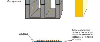
- according to a circuit with a midpoint of the winding (Mitkevich circuit).
Let's compare both of these circuits for the same value of rectified voltage. The bridge circuit uses fewer turns of the transformer secondary winding, which is an advantage. But at the same time, four diodes are needed in a single-phase rectifier bridge. The midpoint circuit requires twice as many turns of the midpoint secondary winding, which is a disadvantage. Another disadvantage of this scheme is the need for symmetry of the winding parts relative to the midpoint.
Voltage stabilizer circuit diagram
Asymmetry will be an additional source of pulsations. But this circuit only needs two diodes, which is an advantage. When rectifying, there is voltage across the diode. Its value almost does not change depending on the current flowing through this diode. Therefore, the power dissipated by a semiconductor diode increases as the rectified current increases.
This is very noticeable at high current levels, and therefore semiconductor diodes are placed on cooling radiators and, if necessary, are blown.
When rectifying high current, two diodes of a midpoint circuit will be more economical and more compact compared to four diodes of a rectifier bridge. Rectifier circuits did not appear out of nowhere back in the day. They were invented by engineers. Therefore, rectifier circuits in the literature are sometimes named in connection with the names of their discoverers. The bridge circuit is referred to as a “full Graetz bridge”. A circuit with a midpoint is a “Mitkevich rectifier”.
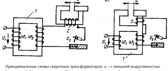
Power transformer
This device is designed to match the voltages at the input and output of the rectifier device. In other words, the transformer separates the load network and the power network. There are various options for connecting the windings of this transformer, the choice of which depends on the type of rectification circuit of the device. The value of the output voltage of transformer U2 is influenced by the voltage value at the output of the rectifier bridge Un.
The transformer is capable of galvanic isolation of frequency f1 from the power supply network U1, I1, and the load circuit from Un, In simultaneously. Currently, it is possible to design and produce high-voltage inverters that operate at higher frequencies and rectify voltage. For this purpose, transformerless rectification schemes are used, in which the valve block is connected directly to the primary power supply network.
Power transformer
Diode bridge
This block performs the main function in the rectifier device, converting alternating current into direct current. The block most often uses elements in the form of diodes. At the output of the valve block, a constant voltage is removed, which has an increased pulse level, which depends on the number of phases of the power supply network and the rectifier circuit.
Diode bridge
Filtration device
The filtering part of the rectifier provides the required level of voltage ripple at the output of the rectifier in accordance with the load requirements. The filter device circuit uses a smoothing choke or resistor connected in series and capacitors connected in parallel with the power output.
However, most often filters are made according to somewhat more complex schemes. In low-power rectifiers there is no need to use a choke and resistor. In rectifier circuits for three-phase networks, the magnitude of the pulses is smaller, thereby making the operating conditions of the filter easier.
What is a voltage rectifier and why is it needed: typical rectifier circuits
Content
- Why do you need a rectifier in electrical engineering?
- Operating principles of rectifiers
- Typical rectifier circuits
- Single-phase rectifiers
- Three-phase rectifiers
- Voltage multiplier rectifiers
Electrical energy is convenient to transport and convert in magnitude in the form of alternating voltage. It is in this form that it is supplied to the end consumer. But many devices still require constant voltage to power them.
Series and parallel connections of diodes.
How to make a simple voltage regulator with your own hands
If for the rectifier circuit it is impossible to select the desired type of diode in accordance with the specified value of the reverse voltage or forward current, then use two or more diodes of the same type with lower parameter values, including these diodes in series or in parallel.
Parallel connection of diodes
Parallel connection of diodes
When connecting diodes in parallel
due to possible scattering of parameters, their currents will be different. One of these currents may exceed the maximum permissible value, which will lead to failure of first one and then the other diode. A more uniform distribution of current between parallel-connected diodes is achieved by connecting resistors Rd of the same value in series with each of them. The resistance of the resistors Rd should be 5...10 times greater than the resistance of the diode in the forward direction. In powerful rectifier devices, inductive current equalizers are used for the same purpose.
Calculation of parallel connection of diodes
To start the calculation, you need to determine the required number of parallel-connected diodes
, based on the fact that the current passing through one diode should not exceed the maximum permissible current value for a given type of diode, then the number of parallel-connected diodes will be equal to
, where
mTnp
For fractional values of the estimated number of diodes, rounding is carried out upward.
value of additional resistors
determined by the formula
, Where
np.cp
The calculated resistance of additional resistors is rounded to the nearest standard resistance.
Example of calculation of parallel connection of diodes
Calculate a rectifier circuit that allows you to obtain a rectified current I rectified = 550 mA if D226B diodes are used.
Since the average forward current of the D226B diode Ipr. av = 300 mA, then it is necessary to use several parallel-connected diodes with additional resistors. Let's calculate the number of parallel-connected diodes, take kT = 0.8
Let's take n = 3.
Let's find the value of the resistance of additional resistors
Let's choose a resistor from the standard range of resistances E24 (± 5%) Rext = 6.2 Ohm
Series connection of diodes
Series connection of diodes
To ensure that the selected type of diode can operate in a rectifier circuit with a reverse voltage exceeding its maximum permissible value, diodes of the same type should be connected in series
. If the parameters do not match, then one of the diodes is under significantly higher voltage than the other. This can lead to breakdown of one and then another diode. Equalization of the reverse voltage on series-connected diodes is achieved by shunting each of the diodes with a resistor Rsh. The current flowing through these resistors should be 5...10 times greater than the maximum possible reverse current of the diodes. In powerful high-voltage rectifier devices, for the same purpose, diodes are shunted with capacitors Сш or an RC circuit.
Calculation of series connection of diodes
To start the calculation, you need to determine the number of diodes connected in series
, based on the fact that the voltage drop on each individual diode should not exceed the amplitude voltage value, then the number of diodes connected in series will be equal to
, Where
Um is the amplitude value of the voltage passing through the diode, kH is the voltage load factor (can take values from 0.5 to 0.8), Uobp max is the maximum permissible reverse voltage of the diode.
For fractional values of the estimated number of diodes, rounding is carried out upward.
Shunt resistor resistance values
determined by the formula
, Where
Iobp max - maximum permissible reverse current of the diode at maximum temperature.
An example of calculating a series connection of diodes
Calculate the rectifier circuit for a voltage with an amplitude value of 700V using D226B diodes.
Since the maximum permissible reverse voltage of the diode is Urev.max = 300V, for rectification it is necessary to use a chain of series-connected diodes with shunt resistors. Let's calculate the number of series diodes, take kH = 0.7
Let's take n = 4
Let's find the value of the resistance of the shunt resistors
Let's choose a resistor from the standard range of resistances E24 (± 5%) Rsh = 1 MOhm
The inclusion of additional and shunt resistors is inevitably associated with an increase in power losses and a decrease in the efficiency of the rectifier circuit.
Circuit of a simple AC rectifier using one diode.
Voltage measuring device. how to measure voltage with a multimeter
Let us analyze the operation diagram of the simplest rectifier, which is shown in the figure:
variable to the input of the rectifier
voltage, in which
positive
half-cycles are highlighted in red and
negative
are highlighted in blue.
Rн
to the output of the rectifier
VD
will perform the function of the rectifying element .
With positive
half cycles of voltage supplied to the anode of the diode, the diode
opens
.
current
Ipr
through the diode, and therefore through the load ( Rн
), powered by the rectifier
wave is shown in red in the right graph).
For negative
Half cycles of voltage supplied to the anode of the diode, the diode
closes
diode
current Irev
will flow throughout the entire circuit .
Here, the diode seems to cut off the negative
half-wave of the alternating current (in the right graph, such a half-wave is shown by a blue dotted line).
As a result, it turns out that through the load ( Rн
), connected to the network through a diode (
VD
), the flow is no longer alternating, since this current flows only in positive half-cycles, and
the pulsating
current is a current of one direction. This is AC rectification.
But this voltage can only power a low-power load that is powered from an AC mains and does not have special power requirements, for example, an incandescent lamp. The voltage will pass through the lamp only during positive half-waves (pulses), so the lamp will flicker weakly at a frequency of 50 Hz . However, due to thermal inertia, the filament will not have time to cool down in the intervals between pulses, and therefore the flickering will be faintly noticeable.
If we power a receiver or power amplifier with this voltage, then in the loudspeaker or speakers we will hear a low-pitched hum with a frequency of 50 Hz, called AC hum
. This will happen because the pulsating current, passing through the load, creates a pulsating voltage in it, which is the source of the background.
This drawback can be partially eliminated if in parallel
connect a high-capacity filtering
electrolytic capacitor
(Cf) to the load.
Charging by current pulses during positive half-cycles, the capacitor ( Cph
) during negative half-cycles
it is discharged
through the load (
Rн
).
If the capacitor is of sufficiently large capacity, then during the time between current pulses it will not have time to be completely discharged, which means that the current will be continuously maintained at the load ( Rн
) both during positive and negative half-cycles. The current maintained by charging the capacitor is shown in the right graph as a solid wavy red line.
But even with such a somewhat smoothed current, it is also impossible to power a receiver or amplifier because they will “phon”, since the ripple level ( Upulse
) is still very noticeable.
half
of the alternating current waves
is usefully used the input
voltage is lost on it and therefore such rectification of alternating current is called
half-wave
, and rectifiers are
half-wave rectifiers
.
These shortcomings are eliminated in rectifiers using a diode bridge
.
Three-phase diode bridge circuit
Generator voltage regulator relay: diagram, principle of operation
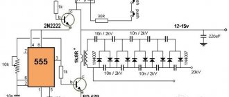
The diode bridge we considered is used for single-phase rectification; it is called a single-phase bridge. To rectify alternating electric current in three-phase networks, a three-phase diode bridge is used.
It consists of 6 diodes, a pair of diodes for each phase. In this circuit, current flows from the phase with the highest potential, through the load to the phase with the lowest potential. The remaining phase is not connected to anything. If in a single-phase bridge two diodes out of four conducted current, then here 2 diodes also conduct current, and 4 are locked.
Diode bridges are produced as complete components, but if such a part is not available, then you can use 4 separate diodes connected according to the diode bridge circuit.
For surface mount boards it is convenient to use dual diodes. For example, from two diode assemblies BAT54S or BAV99 a full-fledged diode bridge is obtained.
Often, using two assemblies of two diodes is cheaper than using a diode bridge of four diodes in one package or four diodes separately.
Post navigation
8 thoughts on “Diode bridge circuit, principle of operation”
What will a sinusoid look like when two phases are connected?
Tricky question. Connecting 3 diode bridges to three phases with a common neutral. That is, on each diode bridge there are N and L1, N and L2, N and L3 220 volts each. At the output from the bridges there is a divider by 100 and a capacitor on a common negative ground. I thought that there was no phase and no output voltage from the diode bridge, but this is not so. So how does a single-phase bridge work, installed 3 times for each phase and united by a common minus?
I hope I imagined this circuit correctly... If we combine the disadvantages of at least 2 diode bridges, we will get an interphase short circuit through the diodes.
If there was a short circuit between the phases, then the 1n4007 diodes (1A, 1000 V) would evaporate into dust. This means there is most likely no short circuit there.
If there was a short circuit there would be a bang, but there isn’t and everything just works crookedly.
How much constant will there be at the exit from the bridge, provided that the phase is equal to 220 V?
If you do not use filters, then after a single-phase diode bridge there will be no constant voltage, there will be a unipolar one. If you install a ripple smoothing capacitor, you can achieve voltage: multiply the input voltage by the root of 2, minus the double drop across the diodes (this is about 2 V). If you look at three-phase circuits, there is less ripple even without filters. The average output voltage will greatly depend on the switching circuit. For example, for a triangle-Larionov circuit, the average output is 1.35 of the current input. And for the Larionov star the coefficient is 2.34.
Let's clarify the terminology a little - then after the real capacitor there will also be no constant voltage. In all cases (even after a single-phase diode bridge) there will be a constant component and an alternating one. In this case, the constant component in the first case will seem to be equal to half the effective voltage minus the drop across the diode (I could be wrong in the quantitative assessment, I’m too lazy to count).” And the variable in the second case will be significantly smaller: the smaller the closer the real capacitor is to the ideal infinite capacitance (with a real voltage source).
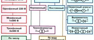
Classification by purpose and device
AC rectifiers are divided into several different types, depending on the characteristics, the use of alternating current periods, circuits, the number of phases and the type of transmitting element. In general, the classification is as follows:
- By the number of periods involved in the work (one- and two-half-wave, as well as with full and incomplete use of the wave);
- By type, devices are divided into those that include an electronic bridge, voltage multipliers, with or without transformers;
- Based on the number of phases, they are divided into single-phase, two-phase, three-phase and N-phase;
- According to the type of device that transmits a sine wave, they are divided into semiconductor diode and thyristor, mechanical and vacuum, mercury;
- Based on the type of transmitted waves, they are divided into pulsed, analog and digital.
Half-wave rectifier (quarter bridge)
It is the simplest device that converts a signal from alternating electric current to direct current. This way the signal level is smoothed. The circuit is built on one semiconductor valve (diode). It is rarely used in industry, since powering automation and equipment requires adding filters to the power circuit that would smooth out the half-wave. Therefore, the size and weight of devices based on this rectifier are too significant. Not suitable for electric current with an industrial signal frequency of 50-60 Hertz.
This rectifier circuit is used in switching power supplies. Required for computer equipment and with a high signal frequency - about 10 Hertz. Also used in industry for rectifying high-frequency current.
The device has the following advantages:
- High frequency pulsation;
- Increased load on the straightening device;
- Deterioration of transformer performance due to magnetization;
- Low ratio of size to power.
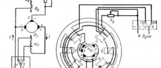
Mechanical voltage rectification
The definition of rectification is to produce a unidirectional electrical current. Its value will depend on the shape of the alternating voltage in each half-cycle. But a unidirectional electric current is obtained both with a positive half-cycle of the voltage and with its negative value. In this case, the load must be disconnected from the unnecessary half-wave of voltage when the voltage passes through zero. The first rectifiers performed this task using mechanical contacts.
They were either driven by a synchronous motor or moved by a fairly fast-acting solenoid. In both circuits, the voltage switching contacts move synchronously with the voltage. In a circuit with a motor, they rotate, closing at the right time. The unit designed to rectify the voltage during rotation is similar to the commutator of a DC motor. The number of lamellas - contacts is determined by the number of revolutions of the synchronous motor.
Circuit for obtaining increased voltage.
When the rectified voltage sinusoid passes through zero, both brushes contact either the beginning or the end of the lamella. The beginning of the lamella coincides with the tip of the arrow indicating the direction of rotation of the engine. The contact time of the brushes with the lamella coincides with the duration of half the period of the rectified voltage.
A synchronous motor rotates precisely and at a multiple of the frequency of the supply voltage, which it rectifies with a commutator attached to it. But its inertia will not allow it to straighten an abrupt change in the frequency of the supply voltage. Therefore, it is only effective as a mains voltage rectifier.
Table of parameters of popular models of voltage rectifiers with photos.
The rectifier on the solenoid closes the contact either while the core is retracted, or vice versa. It can only operate at a certain minimum voltage, which is sufficient to move the contacts. Therefore, the part of the half-wave near the voltage zero crossing will not be processed properly.
But such a rectifier can be made quite small. Therefore, it was widespread in its time. It is obvious that without switching the electrical circuit, there cannot be voltage rectification. And the possibilities of mechanical contact are limited by the power of the spark, which occurs at the moment the electrical circuit breaks. It gradually destroys this contact, the faster the greater the electrical power when it opens.
Why do you need a rectifier in electrical engineering?
The task of converting alternating voltage to direct voltage is assigned to rectifiers. This device is widely used, and the main areas of use of rectifying devices in radio and electrical engineering are:
- generation of direct current for power electrical installations (traction substations, electrolysis plants, excitation systems for synchronous generators) and powerful DC motors;
- power supplies for electronic devices;
- detection of modulated radio signals;
- generation of a constant voltage proportional to the input signal level for the construction of automatic gain control systems.
The full range of applications of rectifiers is vast, and it is impossible to list it in one review.
General characteristics of rectifier diodes.
Depending on the value of the maximum permissible forward current, rectifier diodes are divided into small
,
medium
and
high
power:
low power
designed for direct current rectification up to 300mA;
average power
– from 300mA to 10A;
high power
- more than 10A.
According to the type of material used, they are divided into germanium
and
silicon
, but today
silicon
rectifier diodes are most widely used due to their physical properties.
Silicon diodes, compared to germanium diodes, have many times lower reverse currents at the same voltage, which makes it possible to obtain diodes with a very high permissible reverse voltage, which can reach 1000 - 1500V, whereas for germanium diodes it is in the range of 100 - 400V .
The performance of silicon diodes remains at temperatures from -60 to +(125 - 150)º C, and germanium diodes - only from -60 to +(70 - 85)º C. This is due to the fact that at temperatures above 85º C the formation of electronic hole pairs becomes so significant that there is a sharp increase in the reverse current and the efficiency of the rectifier decreases.
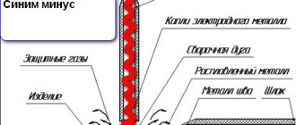
Full Wave Semi-Controlled Bridge Rectifier
Full-wave rectification has many advantages over the simpler half-wave rectifier, such as the output voltage is more consistent, has a higher average output voltage, the input frequency doubles during the rectification process, and requires a smaller value of smoothing capacitor, if any. But we can improve the bridge rectifier design by using thyristors instead of diodes in its design.
By replacing the diodes inside a single-phase bridge rectifier with thyristors, we can create a phase-controlled AC-to-DC rectifier to convert the constant AC supply voltage into a controlled DC output voltage. Phase-controlled rectifiers, semi-controlled or fully controlled, have many applications in AC power supplies and motor control.
A single-phase bridge rectifier is what is called an "uncontrolled rectifier" in the sense that the applied input voltage is transferred directly to the output terminals, providing a fixed average value of the equivalent DC current. To convert an uncontrolled bridge rectifier into a single-phase semi-controlled rectifier circuit, we simply need to replace the two diodes with thyristors (SCRs) as shown in the figure.
In a semi-controlled rectifier configuration, the average DC load voltage is controlled using two thyristors and two diodes. As we learned in our lesson on thyristors, a thyristor will conduct ("ON" state) only when its anode (A) is more positive than its cathode (K) and a trigger pulse is applied to its gate (G). Otherwise it remains inactive.
We also learned that once turned on, the thyristor turns off again only after its gate signal is removed and the anode current has dropped below the thyristors' holding current IH as the variable AC supply voltage biases it. Thus, by delaying the trigger pulse applied to the gate terminal of the thyristors for a controlled period of time or angle (α) after the AC supply voltage has passed the zero voltage crossing between the anode and cathode voltages, we can control when the thyristor begins to conduct current and , therefore, monitor the average output voltage.
During the positive half-cycle of the input signal, current flows along the path: SCR 1 and D 2 and back to the power source. During the negative half cycle of V IN, conduction passes through SCR 2 and D 1 and returns to the power source.
It is clear that one thyristor from the upper group (SCR 1 or SCR 2) and its corresponding diode from the lower group (D 2 or D 1) must conduct together in order for any load current to flow.
Thus, the average output voltage V AVE depends on the firing angle α for two thyristors connected in a semi-controlled rectifier, since the two diodes are uncontrolled and pass current whenever forward biased. Thus, for any gate angle α, the average output voltage is given by:
Note that the maximum average output voltage occurs when α = 1, but is still 0.637 * V MAX, as for a single-phase uncontrolled bridge rectifier. We can use this idea to control the average output voltage of the bridge one step further by replacing all four diodes with thyristors, giving us a fully controlled bridge rectifier circuit
We can use this idea to control the average output voltage of the bridge one step further by replacing all four diodes with thyristors, giving us a fully controlled bridge rectifier circuit.
Why do you need a current rectifier?
Most electrical appliances use direct current during their operation. However, transmitting it over a significant distance is not the most profitable solution, since, as a rule, low voltage is used, and in this case the loss rate will be too large. That is why power lines ensure the transmission of high voltage alternating current, and then the voltage decreases at transformer substations (it is simply technically impossible to create a direct current transformer). This means that alternating current will have to be converted to direct current for the successful functioning of household devices. Such AC converters are called rectifiers.
What are diodes
Diode assembly diagram From the above figure it can be seen that the bridge circuit includes four semiconductor diode elements, the order of connection of which corresponds to the back-to-back principle. Any voltage conversion requires the use of diode bridges.
An excess charge of one sign causes carriers to repel each other, while an area with an opposite charge tends to attract them towards itself. In electronics, this circuit is currently used everywhere.
More powerful rectifier diode bridges require cooling, as they get very hot during operation. During the positive half-cycle, positive voltage is applied to the anode VD1, and negative voltage is applied to the cathode VD3. In a conventional lighting circuit, an alternating current flows, which changes its magnitude and direction 50 times within one second.
Diode bridge circuit This is a so-called single-phase rectifier bridge, one of several types of rectifiers that are actively used in electronics. Its transformation into a permanent one is a fairly common need. There is a potential barrier in the area where the n- and p-type material joins.
Physical properties of pn junction
It will also discuss the issue of how to make a diode bridge with your own hands. The resulting excess electrons form a negative charge, and the holes form a positive charge. But the most interesting thing is that two types of conductivity can exist in one piece of semiconductor. A few words about how a diode bridge works.
Circuit and principle of operation of a diode bridge In this circuit, 4 diodes connected in a bridge circuit are connected to an alternating voltage source V. Diode Previously, in the era of glass electronic vacuum tubes, this was the simplest of the tubes.
If you look at the circuit diagrams of power supplies, both transformer and pulsed, then after the rectifier there is always an electrolytic capacitor that smoothes out current ripples
It is important to note that the current In flowing through the load Rн does not change in direction, that is, it is constant
The voltage removed from the secondary step-down winding of transformer T is subject to rectification. When the LED connected through the limiting resistor lights up, you can be sure that a constant potential has appeared at the output. In this circuit, current flows from the phase with the highest potential, through the load to the phase with the lowest potential. Because the anode is cold, and a positive potential is now applied to the cathode, which returns the electrons ejected by the cathode heat back. However, some examples of modern electronic devices, your mobile, for example, require constant or rectified voltage. Methods for connecting diode bridges and rectifiers to increase their maximum current and voltage
A diode bridge will help convert alternating current into direct current - the diagram and principle of operation of this device are given below. In a conventional lighting circuit, an alternating current flows, which changes its magnitude and direction 50 times within one second. Its transformation into a permanent one is a fairly common need.
Rectifier
Electric current rectifiers are various signal converters. According to the nature of the device, they can be semiconductors based on diodes or transistors, mechanical or vacuum. The function of the unit is to convert an alternating signal going to the input into a constant one at the output. Most of these devices can create a pulsating electrical current, leaving a ripple at the output. Therefore, it is necessary to additionally equip the circuit with filters that would smooth out the oscillations. A device that converts direct current into alternating current is called an inverter and is used in uninterruptible power supplies and batteries.