Setting up the machine for thread cutting
Setting up a modern universal screw-cutting lathe for thread cutting comes down to setting up the drives for the main movement and the feed movement.
Setting the feed box to the pitch of the thread being cut is in most cases carried out using a table mounted on the machine, or according to a passport.
The feed box control handles are set to the position indicated in the table, and the reverse of the lead screw is set to the position corresponding to cutting a right-handed or left-handed thread, and, if necessary, turn on a link for increasing the thread pitch.
Rotation from the feed box is imparted to the lead screw, and the longitudinal movement of the caliper with the threaded cutter is activated when the split nut is closed.
When cutting high-precision threads or with a non-standard pitch, adjusting the longitudinal feed chain requires preliminary calculations, sometimes quite complex (for example, when adjusting a screw-cutting chain not with a feed box, but with a guitar of interchangeable wheels). Modern universal lathes provide the ability to completely disable the feed box; The driven shaft of the guitar is connected directly to the lead screw of the machine. In these cases, it is necessary to select replacement wheels from those included with the machine or make additional ones. The number of teeth on replacement wheels can be selected in two ways.
In the first method, the feed box levers are placed in a position in which the cut pitch is equal to the pitch of the machine lead screw. Thus, the gear ratio is equal to the pitch of the threaded screw divided by the pitch of the lead screw. In cases where the numerator or denominator of the gear ratio of a simple fraction will have factors that are inconvenient for converting them into the number of teeth of replacement gears, the calculation should be carried out using tables of gear ratios.
In the second method, the selection of replacement wheels is carried out according to one of the gear ratios of the replacement wheels available (even from other machines), or according to the gear ratio of the feed box.
If it is necessary to produce a thread with small pitch tolerances, and the machine lead screw has a manufacturing error, then the selection is performed using approximate methods.
Features of setting up lathes
Home » Articles » Professionally about metalworking » LathesWe recommend purchasing:
Installations for automatic welding of longitudinal seams of shells - in stock!
High performance, convenience, ease of operation and reliability in operation.
Welding screens and protective curtains are in stock!
Radiation protection when welding and cutting. Big choice. Delivery throughout Russia!
Before you begin setting up the lathe, you must prepare it for work in accordance with the instructions. Before starting work, the turner must make sure that the machine carries out all commands and that the movements of the support slide (manually and automatically) are carried out smoothly, without jumps, jerking or jamming. First, you need to check that the chuck is securely fastened to the machine spindle, then at idle speed, check that the machine is following commands to start and stop the electric motor, turn the spindle rotation on and off, and turn on and off the mechanical feeds of the support.
After making sure that the machine is in good working order, we begin setting it up.
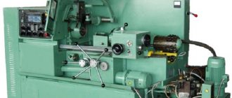
Let's look at the setup using the example of the most universal lathe of the lathe group - a screw-cutting lathe with manual control.
Setting cutting modes
consists of kinematic preparation of the machine for processing the workpiece in accordance with the selected or specified cutting mode. To do this, adjust the kinematic chains of the machine, setting the speed controls of the main movement and feed to the proper positions. Often, the required gear ratios of the adjusted chains are pre-calculated, then these ratios are established using the gearbox and feedbox handles, switching the rotation speed of the adjustable electric motor, installing the appropriate gears, replaceable cams, copiers, etc.
Setting the speed chain of modern screw-cutting lathes does not require any calculations and consists of switching the gearbox handles to positions corresponding to the specified spindle speed. To reduce switching time, machines have tables indicating which position of the handles corresponds to a certain speed value. With stepless control, the spindle rotation speed is indicated by a dial gauge.
The feed movement during turning is communicated by the running roller to the support carriage or its transverse slide. The required feed per spindle revolution is set by switching the handles without any calculations. To facilitate the switching process, the values of possible feeds are pre-calculated and presented in the form of tables given in the machine passport.
When cutting threads, both tuning elements are used - the feed box and the guitar of replacement wheels, which are rebuilt only when the type of threads being cut changes. The replacement wheels required for this are supplied with the machine. Switching the gear banks in the feed box and changing the guitar gears ensures the machine is set up to cut most standard threads. The list of standard threads is given in the passports of the corresponding models of lathes.
The screw-cutting chain of a screw-cutting lathe is shown schematically in Fig. 9.1. In some machine models, the feed chain may also have gears with a constant total gear ratio (not shown in the figure).
The adjustment elements of the screw-cutting chain are calculated and adjusted in such a way that the longitudinal movement of the caliper per one revolution of the spindle exactly corresponds to the pitch (When cutting multi-start threads, the chain is adjusted to the thread stroke, which is equal to the product of the thread pitch and the number of its starts) P of the thread being cut.
Total gear ratio of the specified screw chain
i'=i'ri'ki'у.ш,
where i'r,i'k and i'у.ш are the gear ratios, respectively, of the replacement gears, feed box and pitch increasing link.
In a specific example, the equation for the kinematic balance of a screw-cutting chain will be written as follows:
1 rev. sp. x i'Pх.в = Р.
To set up the machine, use the following dependency:
i' = Р/Рх.в
The pitch of the cut thread P and the pitch of the lead screw with the value Px.v must be indicated in the same units of measurement.
Installation and fastening of cutting tools on machines
are produced using a variety of devices (holders, mandrels, cutting blocks), which are related to auxiliary tools and in most cases are normalized.
The next adjustment element is the selection and installation of the cutter in the tool holder along the height of the axis of the machine centers (Fig. 9.2). To do this, the tool holder is brought to the center of the tailstock, the top of the cutter head is set so that the overhang of the cutter does not exceed 1...1.5 times the height of its holder, the relative position of the top of the cutter head and the center of the machine is determined and their height is aligned by introducing shims under the cutter holder. The shims must have parallel and well-finished surfaces, and their length and width must not extend beyond the supporting surface of the tool holder. The number of pads should be no more than two.
Clamping fixtures
. Depending on how the workpiece should be installed and secured on the machine - in the centers, in the chuck, etc. - fixtures are selected.
For example, when installing a three-jaw self-centering chuck on a machine spindle, first wipe the threads or the tapered end and the tapered bore of the spindle with a cleaning material lightly moistened with kerosene. Then clean the internal threads or the conical hole of the adapter flange of the cartridge. A guide mandrel is inserted into the conical hole of the spindle with a sharp movement (Fig. 9.3, a); take the cartridge with both hands (Fig. 9.3, b) and carefully put it on the guide mandrel. Next, moving the chuck to the left and rotating it, the first threads of the spindle and chuck threads are aligned.
Then, supporting the cartridge with your left hand from below and simultaneously rotating it with your right hand, turn the cartridge until it stops. Using a key inserted into one of the square holes of the cartridge, pull it slightly towards you and sharply (with effort) turn it away from you until it stops (Fig. 9.3, c). To avoid self-unscrewing of the cartridge, the teeth of the locking blocks are inserted into the grooves of the spindle and firmly secured with screws; remove the guide mandrel by pushing it (with a light blow) with a brass rod through the hole in the spindle.
To install a workpiece in a three-jaw self-centering chuck, with your left hand, open the jaws of the chuck with a wrench (Fig. 9.3, d) so that the workpiece passes between the jaws; With your right hand, insert the workpiece between the jaws and first clamp it with your left hand, and then, rotating the key with both hands, finally secure the workpiece in the chuck.
If the processing is carried out in the centers, then to remove the chuck (Fig. 9.3, d), the chuck jaws are first moved apart and the mandrel is secured in the spindle hole; then they remove the locking blocks and, having inserted the key into the chuck socket, sharply turn the chuck toward themselves, and then, supporting the chuck with their left hand and intercepting it with their right, carefully screw the chuck onto the mandrel and remove it from the machine.
After removing the mandrel, carefully wipe the tapered bore of the spindle and the tapered shank of the center. Then, with your right hand, insert the center (shank) into the spindle hole and with a sharp movement insert it until it stops (Fig. 9.4, a). Turn on the spindle rotation and check the center for radial runout. If the center rotates with beating, then it is knocked out with a brass rod and reinserted into the spindle hole, rotated 30...45° around the axis. Then, with your left hand, insert the center into the tailstock quill. To check the alignment of the centers, the tailstock is moved to the left so that the distance between the tops of the centers is no more than 0.5 mm; fix the quill and check (by eye) the coincidence of the vertices in the horizontal plane. If the tops of the centers do not coincide, then their alignment is achieved by shifting the tailstock. After this, the drive chuck is installed (Fig. 9.4, b), using the same techniques as when installing a three-jaw chuck.
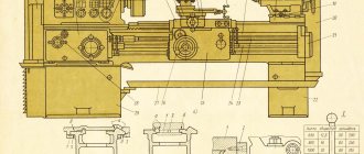
Specification of the main components and controls of the lathe
Main components and controls of the 1k62 lathe
List of controls for the 1K62 lathe
- Switching handle for feed, thread, lead screw and Archimedean spiral;
- Handles for setting spindle speeds;
- Handle for setting increased, normal thread pitch and position when dividing into multi-lead threads;
- Handle for setting right and left threads and feed;
- Handles for setting spindle speeds;
- Button for turning on the rack and pinion gear when cutting threads;
- Handle for indexing and securing the cutting head
- Caliper cross feed handle;
- Push-button station for starting and stopping the main drive electric motor;
- Feed handle for the upper part of the caliper;
- Handle for controlling rapid movements of the carriage and support;
- Tailstock quill fastening handle;
- Cooling pump switch;
- Line switch;
- Tailstock fastening handle;
- Local lighting switch;
- Handwheel for moving the tailstock quill;
- Handles for turning on, turning off and reversing the spindle;
- Handle for turning on the uterine nut;
- Handwheel for manual movement of the caliper and carriage;
- Handles for turning on, turning off and reversing the spindle;
- Handle for setting the feed rate and thread pitch.
Specification of components of the lathe 1K62
- Front headstock (gearbox) - 1K62.02.01
- Bed - 1K62.01.01
- Apron - 1K62.06.01
- Carriage - 1K62.05.01; Caliper - 1K62.04.01
- Cooling - 1K62.14.01
- Rear headstock - 1К62.03.01
- Motor installation - 1K62.15.01
- Feed box - 1К62.07.01
- Electrical equipment - 1K62.18.01
- Slope - 1K62.78.01; Replaceable gears - 1K62.78.02
- Fencing - 1K62.50.01
- Switching - 1K62.11.01
Brief description of the main components of the 1K62 lathe
Headstock
The headstock serves to communicate to the spindle various rotation speeds when cutting, drilling, threading and drives replaceable tilt gears. The headstock mechanism allows:
- a) cut threads with an increased pitch of 4 and 16 times, the gear ratio between the feed chain and the spindle increases by 8 and 32 times;
- b) cut right-hand and left-hand threads;
- c) cut multi-start threads divided into 2, 3, 4, 5, 6, 10, 12, 15, 20, 30 and 60 starts.
The headstock is installed on the center line in a horizontal plane with two set screws and two locking screws 1 (Fig. 5).
The spindle speed is set by two handles 5 and 9 (see Fig. 3). By turning the handle 9, which, through a mechanism with a lantern gear and the shift fork, moves the gear blocks 17-18, 19-20 and 24-25 (see Fig. 4), the required number of revolutions is selected according to table 6, placed under the handle. By rotating handle 5, which, using a flat copier with a closed curve, a lever mechanism and shift forks, moves gear blocks 9-10 and 11-12-13, the required number of spindle revolutions is set from the range selected by handle 9. When setting a number of revolutions 630 —2000 handle 9 must be tilted forward away from you and then turned to the left. The switching device allows you to obtain 23 different speeds of forward rotation of the spindle and 12 speeds of reverse rotation.
The friction clutch, as well as the main drive band brake, is turned on and off using handles 28 and 37 (Fig. 3). When you turn on the forward rotation of the spindle, one of the handles should be raised up, when you turn on the reverse one, lower it down. When handles 28 and 37 return to the middle position, the band brake is activated.
Gearbox
The feed box mechanism allows, through a lead screw with a pitch of 12 mm (without a pitch increasing link), to obtain the following threads:
- a) metric in increments from 0.87 to 12 mm;
- b) inch from 2 to 24 threads per 1″;
- c) modular from 0.5 to 3 modules;
- d) pitches from 1 to 96 pitches.
Using the mechanism for increasing the pitch, at spindle speeds from 12.5 to 40, it is possible to obtain threads with an increased pitch, 32 times larger than normal, and at speeds from 50 to 160, 8 times in accordance with the data in the table on handle 38 (see Fig. Fig. 3).
Through the running roller, the caliper at any number of spindle revolutions receives longitudinal feeds from 0.07 to 2.08 mm/rev and transverse feeds from 0.035 to 1.04 mm/rev, and at speeds from 50 to 630 per minute - longitudinal feeds from 2 .28 to 4.16 mm/rev and transverse from 1.14 to 2.08 mm/rev.
To cut more precise threads in the feed box, handle position 2 is provided (Fig. 3), in which the lead screw is engaged directly, bypassing the feed box mechanism. In this case, the required pitch is selected using interchangeable gears of a special set.
By turning handle 38, the choice of a number of threads or feeds is determined. To obtain the required value from the selected row of threads or feed, it is necessary to pull the drum disk out of the handle towards you, turn until the marks of the disk coincide with the corresponding column of the drum table, and then move the disk forward to its previous position.
To carry out rapid movements of the caliper, an overrunning clutch is mounted in the feed box on the output shaft.
Apron
The apron has four cam clutches, allowing for forward and reverse movement of the carriage and support. The movements of the carriage and the lower part of the support are controlled by the mnemonic handle 16 (see Fig. 3). The direction in which the handle is turned on coincides with the direction in which the caliper moves. The inclusion of fast movements of the caliper in the indicated four directions is carried out by additionally pressing the button 15, built into the handle 16. This pressing turns on the high-speed electric motor, which, through a V-belt drive, communicates movement to the drive shaft.
The apron has a blocking device that prevents the simultaneous activation of the longitudinal and transverse feeds of the caliper, and the simultaneous activation of the lead screw and the lead roller. as well as a safety cam clutch, which is activated under the influence of forces generated when the apron is overloaded.
To cut a thread, use handle 31 to turn on the lead screw nut and disengage the rack and pinion gear by pulling button 35 toward you.
Working on woodworking machines: rules of safe behavior
This article provides basic rules for safe behavior when working on woodworking machines. Their implementation will reduce the number of accidents at work and their severity.
General safety rules when working on woodworking machines
Let's look at the general safety rules when working on woodworking machines.
1. The workplace and passages to it must be kept clean and not cluttered with parts, workpieces, or production waste.
The likelihood of a worker falling is reduced.
2. Parts of woodworking equipment that pose a danger must be painted in signal colors and marked with an appropriate safety sign. The directions of rotation of the cutting parts must be clearly marked on the machines.
The likelihood of your hand getting into the danger zone of the machine is reduced.
3. Moving parts of woodworking equipment, which are a possible source of injury, must be fenced.
Eliminating or reducing the possibility of injury to the worker.
4. For woodworking machines, the working part of cutting tools (saws, cutters, cutter heads, etc.) must be closed by an automatically operating fence that opens during the passage of the material or tool being processed only to allow it to pass in accordance with the dimensions of the material being processed in height and width .
Avoiding injury to the worker's hands.
5. Guards for cutting tools that must be opened or removed to replace and straighten the tool, as well as protective devices for belt, gear and friction drives, drive and driven sprockets of chain conveyors, which can be opened or removed without the use of assembly tools, must be interlocked with starting and braking devices.
Eliminating the possibility of the machine turning on spontaneously.
6. The design and location of hand and foot controls must prevent spontaneous or accidental activation of the machine or its working parts.
Reducing the likelihood of injury.
7. All controls, with the exception of emergency shutdown buttons with a red mushroom-shaped pusher, must have clearly marked signs or inscriptions that precisely define their purpose.
Reducing the likelihood of the machine being turned on incorrectly.
Preparing a woodworking machine for work
When preparing a woodworking machine for work, it is necessary to check the presence and serviceability of:
– protective devices for moving parts of the machine;
– fencing devices for live parts of the machine;
– grounding devices;
– devices for securing cutting tools;
– fastening tools and accessories.
When working on a circular saw you should:
– make sure the saws are in good working order. Saws mounted on the same shaft must have the same nominal diameter, thickness, tooth profile, number of teeth, set or flattening. Saws should not have broken teeth, metal corrosion, cracks, delaminations, the width of the slot for the saw in the machine table should be no more than 10 mm;
– check the serviceability of the riving and guide knives and their fastening (on machines for longitudinal sawing);
– make sure that there are at least two curtains of movable safety stops in front of the saws (on machines for longitudinal sawing of wood). The curtains must provide protection across the entire width of the machine clearance. Devices for lifting the curtain from the stops must be interlocked with the starting and braking device of the machine;
– make sure that the machine for cross-cutting wood is equipped with two-hand controls, eliminating the possibility of turning on the machine with one hand;
– check the presence of a guard for the rear sector of the saw blade on a cross-cutting machine with manual feed of material to the saw;
– make sure that there is a saw guard and a lock on the cross-cutting machine with a bottom-mounted saw;
When working on a planing machine you must:
– check the balancing of the knife shafts, the reliability of fastening the knives and cutters;
– make sure that there are built-in anti-kickout devices on the feed side (on thicknesser and 4-sided planers). When these devices are turned off, the feed drive in the processing direction should be automatically turned off;
– check the presence and serviceability of a locking device that does not allow the table to be moved in height by a mechanical drive with a rotating knife shaft (on thicknessing machines);
– make sure that the retractable guard of the non-working part of the cutting tool of the jointer and 4-sided planer is available and in good condition in accordance with the width of the workpieces being processed;
– check the presence and reliability of fastening of the adjustable guide ruler;
– inspect the edge of the table, located at the knife shaft of the jointer, and make sure that there is a sharply beveled steel pad fixed flush with the working surface of the table. The edge of the lining must be smooth, without dents or nicks.
When working on a milling machine you should:
– check the condition of the cutters and the reliability of their fastening. The milling tool and tool chucks must be balanced;
– make sure that there is a locking device that prevents the machine from being turned on when the spindle is locked.
When working on a grinding machine you must:
– make sure that the sanding belts on wide-belt machines are completely closed;
– check the presence of a guard on the upper (non-working) part of the sanding belt on narrow-belt machines;
– make sure that the disk of disc grinding machines, with the exception of the working area of the grinding surface, is covered with a guard;
– make sure that there are locking devices that do not allow the machine to be turned on when the exhaust ventilation is turned off to remove grinding waste and when the guard covers are removed and open.
Performing work on woodworking machines: what is prohibited
When performing work on woodworking machines, the following is not allowed:
– turn on and off (except in emergency cases) machines and mechanisms, the work of which is not assigned by the immediate supervisor;
– carry out work on machines with safety guards removed;
– touch electrical wires and housings of operating electric motors;
– work on faulty machines and faulty tools;
– work in gloves or mittens on circular saws, planers, tenoning, drilling and other woodworking machines, where personal protective equipment can be caught by rotating and (or) moving parts of the equipment;
– repair, lubricate and clean machines, install belts, remove blockages until the machine stops completely, disconnects it from the power supply and takes measures to prevent its accidental activation;
– process logs and workpieces that have metal inclusions, through cracks and have been rotted.
Alexander Zhuk , occupational safety engineer
Graphic symbols on a screw-cutting lathe 1K62
Graphic symbols on a screw-cutting lathe 1k62
Graphic symbols on a screw-cutting lathe 1k62
Graphic symbols on a screw-cutting lathe 1k62
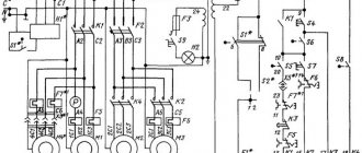
Kinematic diagram of a screw-cutting lathe 1K62
Kinematic diagram of a screw-cutting lathe 1k62
Legend
Mf6 - overrunning clutch to turn off the feed chain from the M2 electric motor when the caliper moves quickly;
Mf7 - safety clutch that slips when the feed mechanism is overloaded;
Mf8, Mf9 - clutches for turning on the caliper feed to the left or right;
z - number of teeth of the stepped cone (block B10, z = 26, 28, 32, 36, 40, 44, 48), with ring gear z = 36;
u2 is the transmission ratio from shaft XII to shaft XIV, which is switched by blocks B11 and B12;
B1..B - gear blocks;
a/b·c/d — replaceable guitar gears (tilt);
P - thread pitch in mm.
Screw-cutting kinematic chain of a screw-cutting lathe 1k62
When cutting all types of threads on a machine, the longitudinal movement of the caliper is carried out by the XV lead screw. To do this, the Mf5 clutch is engaged, and the z=10 gear is disengaged from the gear rack. The caliper is fed when the lead screw nut XV is turned on.
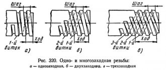
Metric thread cutting
Setting up the feed mechanism for cutting this thread is done by installing the B8 and B9 guitar blocks so that the transmission is carried out through wheels with a gear ratio uVIII-IX = (42/95)·(95/50) by turning on the Mf2, Mf3 and Mf5 couplings. Block B10 becomes the leader in this case.
The balance equation for a screw-cutting chain will be written as follows:
By substituting seven values of z (26, 28, 32, 36, 40, 44, 48) and four values of u2 (1/8; 1/4; 1/2; 1), one can obtain 28 thread pitch values ranging from P = 26/4 · 1/8 = 0.8125 to P28 = 48/4 = 12 mm. Of the 28, only 19 pitch values coincide with the metric threads used.
Modular thread cutting
Setting up the feed mechanism for cutting modular threads is done in the same way as for cutting metric threads, only the B8 and B9 guitar blocks are installed so that the transmission is carried out through wheels with a gear ratio u'VIII-IX = (64/95) · (95/97) , while the resulting thread pitch changes by a number of times equal to (64/95 · 95/97): (42/95 · 95/50) = 64/97 · 50/42 = 3200 / 4074 = 0.78552. Therefore, the resulting modular thread pitch is P' = 0.78552 zu2/4, and the module m = P/ /π = 0.78552 / 3.14 zu2/4 = 1/4 zu2/4.
Inch thread cutting
Setting up the feed mechanism for cutting these threads is done in the same way as for metric ones, but in this case only the Mf5 coupling is turned on, and all the others are turned off. As a result of this, the B10 gear block becomes driven.
The balance equation of the kinematic chain in this case will be written as follows:
Inch threads are characterized not by pitch, but by the number of threads K per inch of thread length. The number of threads is found from the formula:
Substituting seven z values and four u2 values into the formula, we get 28 different values of K, of which 20 are standard values.
Pitch thread cutting
When cutting pitch threads, the same kinematic chain is used as when cutting inch threads, only instead of 42/95 · 95/50 wheels, replaceable gear wheels 64/95 · 95/97 are installed on the guitar. In this case, the resulting thread pitch changes by a factor of 0.78552 and is equal to P = 0.78552 16 25.4 (u2/z), and K = z/0.78552 16.
It is known that between the pitch Dp and the number of threads K per inch there is a relationship Dp = Kπ. Therefore Dp = Кπ = πz / 0.78552 · 16u2 = 4z/16u2 = z/4u2.
Long pitch thread cutting
All kinematic chains written earlier related to threads with normal pitch.
To obtain an increased thread pitch, gear z=46 of block B6 is engaged with gear z=45 of shaft III. In this case, transmission from shaft VI to shaft VII is carried out through shafts V, IV and III with the following gear ratios:
a) at a spindle speed in the range n = 12.5..40 rpm (u search = 1/16)
b) at spindle speed in the range n = 50..160 rpm (u search = 1/4)
As a result, the resulting pitch of metric and modular threads increases by 8 or 32 times, and the number of threads per inch and pitch decreases by the same number of times.
When cutting threads with an increased pitch, a higher spindle speed than 160 rpm is not used.
Cutting precision threads
When cutting these threads, couplings Mf2, Mf4, Mf5 are activated. In this case, the transmission is carried out from the spindle through the replaceable guitar gears uVIII-IX = a/b·c/d to the IX shaft and then directly to the XV lead screw.
The balance equation of the screw-cutting kinematic chain in this case will be written as follows:
From the equation we obtain formulas for selecting the numbers of teeth of replacement guitar wheels:
for metric thread: a/b c/d = P/12 ;
for modular thread Р=πт we get a/b·c/d = πт/12 = 11m/42 ;
for inch thread P=25.4/K we get a/b c/d = 25.4/12K = 127/60K ;
for pitch thread P=25.4π/Dp we obtain a/b·c/d = 25.4π/12Dp = 127·11 / 30·7Dp .
A set of replacement gears needed for cutting precise threads is supplied to the 1K62 machine upon special order.
Commissioning of machines. General information.
Before performing any adjustment work, it is necessary to prepare the machine and carry out its initial start-up.
This stage at the manufacturing plant begins after assembling the equipment, and at the consumer plant - after completion of installation, i.e., installing the machines on the foundation and connecting the necessary communications (lubricating fluid, compressed air, etc.).
Preparation of the machine and its initial start-up includes the following work:
- a detailed study of the passport and maintenance manual of the machine, the features of its design and operation, the principle of operation of the controls and locking system, the purpose of all buttons and signal lights, recommendations for setting up equipment, as well as general and special safety rules related to this type of machine;
- preparation of the workplace near the equipment being serviced: rational arrangement of equipment (table, cabinet for tools and equipment, etc.), tools and accessories;
- removing (if necessary) the anti-corrosion coating from the machine and carrying out lubrication work in accordance with the instructions;
- preparation for launch of the electrical equipment system in compliance with all safety regulations;
- checking the presence of lubricant and, if necessary, adjusting the safety valve;
- preparing for the start-up of the hydraulic drive and checking the direction of rotation of electric motors of hydraulic power stations, the condition of filters and filling of pipelines with oil, removing air from the hydraulic system and adjusting the valves;
- checking the supply of compressed air and cutting fluid;
- visual check of the condition of the guide frames, tables, supports and other components for the absence of nicks, rust and other defects;
- delivery of a set of cutting, measuring and auxiliary tools according to the nomenclature specified in the technological operating chart and in the required quantity;
- obtaining the required number of blanks with the rejection of unsuitable ones.
After eliminating all identified deficiencies, the initial start-up of the equipment is carried out at idle speed (should operate for 2...4 hours).
During the start-up process, check that sufficient quantities of oil are supplied to all designated points. Lubrication is carried out according to the map given in the machine service manual.
Check for oil leaks at pipeline connections, hydraulic panel joints, covers and other places.
The oil pressure in hydraulic systems and air pressure in pneumatic systems correspond to the specified values. They control the operation of the “Start” and “Stop” buttons, signal lights and interlocks of individual equipment components. Check the smooth movement (absence of jerking and jamming) of the table, supports and other moving components, as well as the absence of jamming and increased noise during operation of gear, worm, chain and other gears.
After testing the equipment at idle speed and eliminating identified deficiencies, adjustment is carried out. It includes setting the specified values for the spindle speed and feed speed when moving the moving parts of the machine (supports, tables, etc.) using the operational adjustment card. For this purpose, gearboxes and feeds are adjusted. They arrange (or, if necessary, check the correct location) of electrical, hydraulic and pneumatic stops and control converters for the operation of units, install clamping chucks and check the correct location of the cutting tool (adjustment to size) according to the operational drawing.
During the process of setting up and operating metal-cutting machines, their geometric accuracy (for example, spindle runout) is periodically checked for compliance with the standards specified in the equipment passport.
Techniques for cutting threads with cutters
After setting up the machine, securing the workpiece, installing and securing the cutter, turn on the machine and begin cutting the thread, slightly deepening the cutter into the metal. A screw mark is obtained on the surface of the part, the pitch of which is checked with a ruler, caliper or thread gauge. Before starting the next pass, the cutter is deepened along the limb by the required amount.
You can cut a triangular thread profile with cutters in the following ways.
First way.
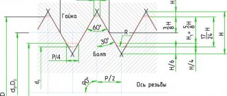
The cutter is installed perpendicular to the axis of the part (Fig. 224, a), using a template, as shown in Fig. 219.
Before each new pass, the cutter is removed from the groove by moving the transverse slide towards itself. Then the machine is reversed, returning the longitudinal slide of the support to its initial position. Upon return of the longitudinal slide, the cutter is given transverse movement (Fig. 224, b). The counting is carried out along the dial of the cross-feed screw. All these techniques are repeated in this way until the thread is cut to the full depth of the profile.
As can be seen from Fig. 224, b, the thread in this case is cut evenly by both cutting edges. During rough cutting, the separated thick chips interfere with each other, so the cutter may jam and produce a rough, torn thread surface; during finishing cutting, when small chips are removed, the surface is clean.
This method of cutting the cutter is used for cutting threads with a pitch Sp less than 2 mm; both on roughing and finishing passes, the cutter is fed for each pass to a depth of t = 0.05.. 0.2 mm.
Second way . If the pitch of the thread being cut is more than 2 mm, the thread is cut with a special cutter (Fig. 225, a). It is installed in the upper part of the caliper, rotated at an angle α/2 equal to half the angle of the thread profile, and is fed by lateral cutting, moving the upper part of the caliper at an angle to the axis of the part in the direction indicated by the arrow. With this installation of the cutter, cutting is carried out mainly by the left cutting edge (Fig. 225, b); the right cutting edge removes very thin chips and therefore wears out slowly.
After each pass, the cutter is removed from the groove by moving the transverse support towards itself (the upper part of the support is not touched). Then the machine is reversed and the longitudinal slide of the support is returned to its initial position. Before each subsequent pass, move the transverse support to its previous position (along the dial or along the stop). The cutter is deepened by moving the upper part of the caliper along the limb.
To obtain a more accurate thread, the final cutting is performed using the first method (see Fig. 224).
Grooves for the exit of the thread cutter. When cutting both external and internal threads on parts with shoulders, it is necessary to provide grooves for the cutter to exit in order to protect it from breakage (Fig. 226 and 227). The depth of the groove should be slightly greater than the depth of the thread, and the width of the groove should be equal to 2-3 thread pitches.
Cutting right and left threads. When cutting a right-hand thread, the lead screw and spindle rotate counterclockwise, and the support with the cutter moves from the tailstock to the front (see Fig. 193, a). When cutting left-hand threads, the bit must be installed so that the lead screw rotates in the opposite direction, that is, clockwise in the normal direction of spindle rotation. In this case, the caliper should move to the tailstock (see Fig. 193, b), therefore, cutting the left-hand thread should begin from the left end of the part, i.e., closest to the headstock.
Cooling. The use of lubricants and coolants when cutting threads is mandatory. Abundant cooling protects the cutter from dulling and helps to obtain clean thread flanks. Emulsions and sulfofresol are recommended as coolants when cutting threads in steel and brass (gives better results); Cast iron parts can be cut dry or with kerosene.
Basic safety rules before starting to work on a lathe
The most dangerous production factor when working on lathes is:
A rotating spindle, shafts, worms, chips, and to put it in one word, all rotating mechanisms of the machine are dangerous.
Before you start working on lathes you need to know:
Start with your work clothes, put them in order, fasten all the buttons or rivets, tie your sleeves tightly or roll them up, and if you have long hair, put it in a hat.
Prepare your workspace:
Check the serviceability of all protective shields and the serviceability of protective limit switches (if any). Safety glasses (must be clean, without scratches or cracks), prepare in advance cutting, measuring tools, devices necessary for the manufacture of this part, containers for workpieces and suitable products, check if everything is in order with the footrest, the floor around the machine must be clean and no oil stains.
Before starting work, check:
Braking mechanisms, control devices, lubrication supply to mechanisms and guides, tension of belts and chains. For such a check, it is enough to drive the machine for several minutes at idle speed, and it will immediately become clear to you whether the machine is working properly or not mechanically. Proceed to work if the machine is fully operational.
When preparing the machine for operation:
When installing cutters, fixtures, equipment, etc., the machine must be in the off position. After installing the cutters, equipment, rotate the spindle by hand and make sure that the cutters do not hit the chuck, spindle and equipment.
Features of safety rules when working and setting up CNC machines:
The operator checks the CNC machine before starting work with test programs. After adjustment, remove all handles and keys.
While the machine is running:
Clamp workpieces and parts firmly into the chuck, mandrels, or centers. When installing and removing workpieces weighing more than 20 kg, use a crane or lifting devices. Under no circumstances leave the key in the chuck after securing or removing a part. Do not touch or brake with your hands a spindle that is turned on or not completely stopped. When removing chips, it is necessary to use tops and metal hooks. Do not clean, wipe, or lubricate the machine when processing the part. When measuring a part, turn off the spindle rotation and take measurements carefully. Be careful when measuring, there may be sharp edges on the parts (you can cut your hands). Cover the cutting area with designated protective covers and screens. When high-speed turning, cutters with chip-breaking grooves or chip-breaking cutters should be used. When removing burrs or polishing, use clamps; do not hold abrasive cloth in your hands. Non-rigid shafts should be processed in steady rests, and the protruding edges of the rod should be protected with tubular casings. It is necessary to work strictly according to the process and set the cutting conditions specified in the technology. Before turning off the spindle rotation, turn off the machine's automatic feed and move the cutting tool away from the workpiece. It is forbidden to work with gloves or bandaged fingers (you can use rubber fingertips). Wipe your hands with a clean rag; do not use a rag to wipe your hands after wiping the machine (you can cut yourself with small shavings). When the spindle rotates more than 150 rpm, do not use rigid centers; when processing large parts, use self-lubricating centers. During breaks, turn off the spindle rotation. If there is a power failure or oil leak, turn off the equipment immediately. It is prohibited to open the doors of electrical cabinets or protective casings of electrical equipment. In case of any malfunctions, notify the foreman or shift supervisor. It is prohibited to start work until the problem is resolved. Keep your work area clean and do not clutter it with parts and workpieces. Make sure that the coolant does not get on the floor and underfloor grate.
After finishing work:
Turn off the machine and de-energize it with the switch, remove chips from the machine and around it with special means, lubricate the guides and rotating shafts and worms with machine oil. Remove cutting and measuring tools.
Cutting threads on screw-cutting lathes 1K62. Video.
Useful links on the topic
- Screw-cutting lathe 1K62
- Screw-cutting lathe 1K625
- Calculation of kinematic settings of screw-cutting lathes 1K62
- Lathe bed. Repair of lathe bed guides
- Headstock of a lathe. Installation and repair of the headstock
- Album of kinematic diagrams and drawings of the 1K62 screw-cutting lathe
- Methodology for checking and testing screw-cutting lathes for accuracy
- Tailstock of a lathe. Repair device and technology
- Lathe support. Repair device and technology
- Lathe apron. Lathe apron design
- Feed box of a lathe. Drawings of the feed box of the lathe 1K62
- Lathe spindle. Lathe spindle repair
- Assembly drawings of screw-cutting lathe 1K62
- Repair and adjustment of screw-cutting lathe 1K62
- Directory of factories producing metal-cutting machines
Catalog directory of screw-cutting lathes and their analogues
Diagrams and passports for screw-cutting lathes and equipment