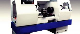
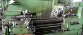
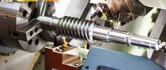
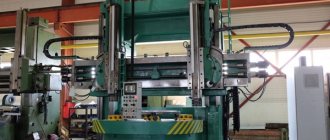
Various equipment is involved in the metalworking process. Turret lathes represent a separate category. According to the principle of operation, they are in many ways similar to universal units.
But on turret machines it is possible to process a workpiece using several tools, and the turner does not need to change or reinstall them.
General technical specifications
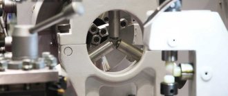
Turret lathes are used in enterprises for mass production of parts. A distinctive feature of the machines of this group is the presence of a turret head for attaching several cutting tools. The equipment is beneficial to use when the technological process involves repeated tool changes.
You can install 4 or more tools at the same time; changing occurs by turning the turret. The tool is installed in the sequence required for work. Due to this, the processing cycle of one part is accelerated compared to a similar process on a universal lathe.
Main characteristics
When choosing a mini, multi-spindle or single-spindle turret lathe, you should pay attention to the following characteristics:
- Accuracy class. To determine the possibility of using a particular machine model for producing workpieces, what class of accuracy can be achieved is taken into account. Most models have an accuracy class N.
- The largest indicators of the dimensions of the workpiece (length and diameter), as well as the placement of nodes relative to each other.
- What material is the workpiece made of? Typically, carbon steel, alloy steel, cast iron or other alloys can be processed. Taking into account the material, the tool and cutting modes are selected.
- Maximum number of revolutions per minute. A part with certain parameters of roughness and dimensional accuracy can only be obtained by unwinding the workpieces to a certain speed. In this case, the number of gears should be taken into account.
- Manufacturers also include information in the description about the speed at which individual components can move during fast feeding. In addition, there is a working feed, which also has a certain speed.
- The power of the installed motor and their number. A small-sized machine is equipped with lower-power motors, since the workpieces are small in size and less metal is removed in one pass. The serial production method determines that the installed motors must withstand long-term operation.
- Overall dimensions of the equipment, as well as its weight. The mini machine is easier to install, since there is no need for preliminary preparation of the base. Large equipment requires careful preparation of the base.
It is worth considering that the kinematic diagram of a turret lathe can also differ significantly. Older models are designed in such a way that in order to cut a certain thread, you have to install certain replacement wheels. For setup, you can use a drawing of a turret lathe.
Classification
Turret turning units are classified according to the following principle:
- In terms of the number of cutting tools - on average, the head has 6-12 slots, but on some modern models their number reaches several dozen.
- The direction of the turret is vertical, horizontal or at an angle.
- By type of control - manual, semi-automatic, CNC.
- According to the principle of operation - rod or for processing piece workpieces.
- By type of workpiece - light (parts made of rod), medium (processing of rod and piece workpieces), heavy (working only with piece workpieces in the chuck).
- Drive type: manual or hydraulic.
What work can it do?
Machines that have a CNC function can perform work on many types of turning: rings, rollers, stepped bolts, bushings.
Many manipulations will involve cutting using special taps and internal and external thread heads.
As well as cutting and leveling the ends , turning the workpiece to a cylindrical shape, pumping sheet workpieces.
Units with a CNC program and without control will have a lead screw, which, with the help of combs and additional cutters, can produce a variety of threads.
When the production of parts is put into production (mass production), specialists often resort to using a thread-cutting head . Such heads have round combs of tangential or radial shape. The highest accuracy of work will be achieved when using round combs.
To perform threading, the cutting size of the head can be from M5 to M65. When threads are made with dies or taps, special holders will be present in their design. During the movement of the caliper, they will help screw in the tap or die using free movement along the axis.
On turret type machines it is also possible to process shaped surfaces . To perform such work, it is necessary to install a curved template (easel pattern) instead of a copy ruler. It is possible to process the surface with specific cutters, which are called shaped cutters.
Purpose of the equipment
Universal turret machines are designed for processing rods up to 100 mm in diameter, as well as for manufacturing products from piece (cast, stamped, etc.) blanks with a diameter of up to 630 mm. What operations can be performed:
- Grinding of external cylindrical surfaces.
- Thread cutting with taps and dies.
- End processing.
- Reaming holes to obtain the desired parameters.
- Grooving.
Reference!
When cutting threads with a cutter, round, radial and tangential dies are used instead. They move in the longitudinal direction, the feed speed is equal to the thread pitch. Processing of complex shaped surfaces is possible. For this purpose, instead of a copy ruler, a curved template is installed. For some operations, shaped cutters are used, which are fed in the transverse direction.
Working on a turret lathe allows you to achieve high processing accuracy. You can also sharpen products that have been rough processed on other equipment.
Important!
It is advisable to use turret group machines in mass production for the manufacture of large batches of similar products.
Features of turning-turret group machines
Both conventional models of turning-turret machines and devices equipped with a CNC system are distinguished by high productivity, which is achieved due to a number of factors.
- These machines are equipped with high-speed mechanisms responsible for fixing the workpiece and feeding it.
- Processing is carried out by effectively combining the work of two supports - transverse and revolving.
- All working devices of the machine are quickly replaced.
- The machines are equipped with multi-tool holders, and combined type tools are used for processing.
Of course, in order for processing on turret lathes to be highly productive, it is necessary to correctly configure all the parameters of their operation. Such parameters, in particular, include:
- a list of working tools and their installation on the equipment in the correct technological sequence;
- adjusting the position of installed tools and working devices in the radial and axial directions;
- qualified installation of stops limiting longitudinal and transverse feeds.
Most turret lathes, in particular the model 1341 and its modification 1K341, which is well known to specialists, are equipped with command devices that provide automatic switching of spindle rotation and feed modes. The use of such devices can significantly reduce the time required to perform auxiliary technological operations.
Models of machines of this group, on which a chuck is installed to fix the part, can be used for processing workpieces whose cross-section is in the range of 16–63 cm. The main characteristics of the units on which bar parts are processed are:
- maximum processing length, depending on the greatest distance that the working head can move;
- the largest section of the part that can be processed above the support or above the bed;
- the maximum distance at which the front edge of the working head can be located from the front edge of the spindle assembly.
Device
The design of the machines as a whole is similar to other groups of turning equipment. The basis is the frame on which the remaining components are located.
Gearbox
On turret machines, the gearbox is built into the spindle head. Depending on the model, it has a certain number of spindle speed and tool feed ranges.
Caliper
The unit carries a turret head for attaching a cutting tool. It is installed in the grooves of the head and secured using special holders. They, in turn, ensure rigidity and reliability of fixation of instruments. The support moves in the longitudinal and transverse directions using manual or automatic feed.
Also located on the caliper are a command device and a stop drum. The command device is responsible for turning on/off the specified speed and feed rate for each tool. The stop drum ensures that the support automatically stops when the tool travels a predetermined distance.
Some models are equipped with a turret and cross slide. The design of the latter allows you to install two tool holders simultaneously with six tools. This is convenient when processing complex parts.
Spindle assembly
This unit provides feeding and fixing of the rod workpiece. The main movement in the machine is the rotation of the spindle with the workpiece in the forward or reverse direction.
The diameter of the spindle hole on a particular unit determines the largest size of bar that can be worked with. Depending on the model, a rod with a maximum diameter of 10, 16, 18, 25, 40, 65, 100 mm can be installed in it.
The spindle rotation speed and feed are adjusted using a command device, or manually by installing the handles located on the spindle head into the desired positions.
Categories of turret group lathes
Turret lathes from domestic manufacturers are classified according to two main parameters.
- Based on the type of parts being processed, such devices are divided into models for bar or chuck work.
- Based on the location of the axis in which the turret head is located, machines are divided into horizontal, vertical and inclined.
Revolving lathes can be equipped with faceplates, three- or four-jaw chucks driven by a manual or hydraulic drive, which makes it possible to process workpieces of significant size. These can be blanks that were previously obtained by forging, stamping or casting.
Types of turrets
A separate category consists of turret group machines, which process rod blanks. The hole in the spindle of such models has a small diameter, and their additional equipment is a mechanism that provides feeding and fixing of the workpiece rod. If necessary, such machines (if equipped with a conventional chuck) process forged, cast and stamped parts.
Depending on the location of the axis of the working head, the machine may have a different number of supports. So, if the axis of the working head is located in a horizontal plane, then on such a machine only a revolving type caliper is installed, capable of performing circular movements and longitudinal feed. If the axis of the working head of a turret lathe is located in a vertical and inclined plane, it may have two supports - a turret and a transverse one. In this case, two tool holders are installed on the latter - front and rear - in which up to six working tools are simultaneously fixed. On the other support is the turret.
Tilt turret
Principle of operation
In mass production, the rod is mounted in a collet chuck using hydraulics. There is a built-in mechanism that ensures that the workpiece is fed to the required length. When working with piece workpieces, the turner secures them manually.
Typically, machines are equipped with a universal collet with replaceable jaws for clamping a circle and a polyhedron. The kit includes additional mandrels, bushings and other accessories.
Important!
On some models, it is possible to replace the collet with a three-jaw chuck.
Modifications of machines for chuck work are designed for processing cast, stamped and forged piece workpieces. They are equipped with three-jaw (or four-jaw) chucks.
All tools are mounted in the turret. Having completed the working stroke with one cutter (drill, reamer), it changes position and feeds a new tool. The length of the tool's working stroke is limited by special stops that shut off the feed.
Purpose and design of CNC turret lathes
When manufacturing medium and large batches of parts on screw-cutting lathes, it is customary to carry out step-by-step metal processing, since each operation requires its own processing modes, type of cutting tool and other equipment settings (for example, checking the zones of mutual influence of cutters). In mass production, such machines often operate in pairs (or using a counter-spindle), forming a single production line, where a product processed on one side is transferred to another machine for further processing. This is due to technological complexity and the impossibility of processing the entire workpiece to the finished product on one machine without readjusting the machine (the number of operations exceeds the number of positions in the turret).
CNC lathe-turret group (two-support, with an inclined bed):
| 1 - engine; 2 — spindle head; 3 — upper longitudinal-transverse caliper, 4 — turret head of the upper caliper; 5 - tailstock; 6 — turret head of the lower caliper; 7 — lower longitudinal-transverse support of the machine. |
Precise processing of products using CNC machines requires competent basing of the workpiece (selection of technological base) and refined settings of the cutting tool (for example, using the HPMA system from Renishaw). This is especially true for parts with complex configurations, with tight tolerances and high requirements for surface accuracy.
By programming the CNC of the machine module and calibrating the cutting tool, the processing accuracy is set. If the head axis can be positioned at different angles to the workpiece, parts with more complex surfaces are obtained.
Safety precautions
Metal processing on lathes is equated to work with increased danger. Workers are allowed into the process only after preliminary instruction. While working, the turner must follow the safety rules:
Firmly fix the workpiece.
- Do not start work if any malfunctions are detected.
- Perform only the work assigned by the master.
- If the return end of the bar protrudes from the spindle, this area must be protected.
- Do not allow the jaws to protrude beyond the outer diameter of the chuck or faceplate. In this case, it is necessary to use other equipment.
- After securing the workpiece, remove the key.
- Do not leave tools in the turret that are no longer in use.
- Measure, remove and install the part after the mechanisms have completely stopped.
- When sanding a product, remove the turret head manually.
- Do not open the protective devices while the machine is operating.
Important!
It is permitted to work on a turret lathe strictly in closed, neat clothing.
Main design features
A universal screw-cutting lathe consists of main structural units, which are standard elements. These include:
- caliper;
- bed;
- thrust and spindle headstock;
- electrical equipment;
- drive shaft;
- guitar gears;
- a box that provides selection and change of feeds;
- lead screw - it is this detail that distinguishes a screw-cutting lathe from a standard lathe.
Depending on some features, the accuracy of the machine may vary. Therefore, universal equipment can be of both accuracy class N and increased – P.
Front and rear stock
The headstock or spindle has the main role of fixing the workpiece in processing and transmitting rotation to the workpiece from the electric motor.
The spindle is located inside the body of the headstock. A speed control handle is mounted on the outside of the machine body. The tailstock or thrust is necessary to fix the workpiece.
Caliper
The support is designed to move the tool holder with the cutter in the longitudinal, transverse direction relative to the axis of the machine. The lower part of the support is called the slide or carriage.
After a certain time of operation of the machine, the support will need to be adjusted, since otherwise the processing speed will decrease. Adjustment for gaps consists of tightening the wedge strip.
Compared to other parts, the caliper is large. The choice of tool holder is determined by the class of the machine. For large equipment, be sure to secure the cutters with an additional four screws.
Gearbox
This is the main part of the spindle drive. It transmits engine energy to the rest of the machine. Another function is to change the spindle speed and the operating speed of the entire machine.
The box is built into the spindle head housing or in a separate housing block. The speed can be changed in a stepless or stepwise manner. The standard gearbox includes the following components:
- gear system;
- V-belt transmission;
- reversible electric motor;
- electromagnetic clutch with braking system;
- handle for changing gears.
The gearbox operates using gears.
Spindle
This is the main part of the machine, which is made in the form of a shaft with a conical hole for securing workpieces. To ensure that the part has high strength and durability, it is made of high-strength steel.
In the classic version, the spindle is made on high-precision rolling bearings. A special ring is installed on the support of the part, which ensures the accuracy of the machine.
There is a conical hole at the end of the structure. The spindle needs a cavity to install a rod that helps, if necessary, knock the center out of the seat.
The strength and durability of the spindle directly depends on the bearings available there.
bed
This is the main part of the machine, which is made using cast iron. All the most important parts and elements of this design are attached to it.
The frame itself consists of two steel beams. The beams, in turn, are connected to each other by stiffening ribs. Each beam has a connection to two guides.
The guides on both sides belong to the prismatic group. The flat-shaped guide is located inside on the left side.
Threading
There are several ways to cut threads using a screw-cutting lathe. For this, a die, tap, cutter and other types of tools are used.
With their help it is possible to cut internal and external threads
When using a cutter, it is important to fully comply with the technology. It includes:
- correct sharpening of the cutter;
- accurate adjustment of machine operating modes;
- using a template, correct installation of the cutter in the center of the part;
- measuring the resulting dimensions using gauges or templates.
In such work, defects in the form of sharp points, torn threads, scuffing and crushing are unacceptable.
Electrical control unit
The standard control unit for a screw-cutting lathe includes several handles and buttons:
- handle for setting the number of revolutions;
- control system for setting cutting surface parameters;
- handles for caliper control.
A CNC machine has a more complex structure, but can work without operator participation at intermediate stages.
Apron
In the apron of a screw-cutting lathe there are mechanisms that convert the rotational movement of the lead screw and the lead shaft into the translational movement of the caliper.
Modern CNC models
Conventional machines are being replaced from production by improved models with program control. They allow you to fully automate the workflow and provide high processing accuracy. There is also no need to take measurements after each pass.
The following equipment models are relevant in modern production.
1V340F30 - equipped with an Electronics NTs-31 CNC device and a turret for 8 tools. Allows you to process piece workpieces with a diameter of no more than 20 cm, as well as produce products from a rod with a diameter of up to 4 cm.
1P426DFZ - equipped with two turrets. The first allows the use of 8 cutting tools and is intended for processing external surfaces. The second head is designed for working with internal surfaces.
ST and DS are a series of American-made CNC turret machines. Universal units designed for processing workpieces of different types of steel.
It is advisable to use turret lathes in mass production for the manufacture of large batches of similar products. But their turret functionality is slightly limited compared to screw-cutting turning units.
Performing some operations (for example, thread cutting, turning shaped surfaces) requires the use of additional devices.
Design and operating principle
In the general case, a turret lathe (Fig. 3) consists of a frame (1) on which the main components are fixed. The gearbox (2) is used to change the rotation speed of the spindle or the clamping and bar feeding mechanism (3). Whether a machine is equipped with a spindle or a bar feed mechanism depends on the specifics of its operation. If a metal rod is used as a raw material for processing, the machine is equipped with a feed mechanism. If the workpiece is a forging or casting, then a standard spindle for this group of metal-cutting machines is installed.
To change the speed of advance of the rod to the turret support (7), there is a feed box (4). To expand the technological capabilities, turret lathes are often equipped with additional devices. The machine presented as a sample for consideration has an additional thread-cutting (5) and copying (6) device. The thread-cutting device is used to create threads according to specified parameters. The copying device is designed to create a surface on the workpiece according to the sample. The turret head is controlled by an apron (8) and a stop drum (9).
There is a pumping station (10), which creates pressure for the operation of hydraulic drives. In the cooling device (11), the temperature of the working fluid decreases. The gearbox (13) serves to reduce the operating speeds of the machine. The drum stop (12) cuts off the feed at the right time. The stand (14) is necessary to support the rod being fed into the work.
Figure 3. Turret lathe for working with rods.
Figure 3. Turret lathe for working with rods.
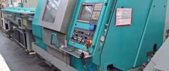
Recently, despite the high cost, modified turret lathes with advanced technological capabilities and numerical control have been in increasing demand. Such machines have high productivity and precision in manufacturing parts. Here the operator’s work comes down to loading the bar as needed, monitoring the operation of the machine and accepting finished products.
Advantages and disadvantages
The significance of the use of lathes with a turret-type tool holder is determined only after a detailed analysis of the functionality of the equipment, as well as its technical characteristics. But no less important is to identify the positive and negative aspects of their work.
— The main advantage of using machines of this group is high productivity. To perform various turning operations, it is not at all necessary to replace the cutting tool every time. It is also worth noting the automation that turret lathes have. But this will only make sense if you have computer numerical control (CNC) installed.
— The only disadvantages include the relatively high cost of the models and the increased complexity of manufacturing along with maintenance. There are also increased demands on staff professionalism. But these factors are negligible and are taken into account only at the stage of developing a production technological scheme.
This is interesting: Drill for ceramic tiles: types, rules for working with drills for tiles
Some features of the operation of revolving units
The high productivity of turret machines and their wide range of applications is achieved by the following features:
- All units are equipped with a special high-speed mechanism. It is designed to fix the workpiece and feed it in the desired direction;
- operational efficiency is ensured by the presence of two calipers, which is not available in other equipment;
- all elements of the machine are replaceable, and if necessary, repairs can be carried out without any difficulties;
- Various tools are used to process parts according to the needs of the user. This allows you to easily perform all the operations required by the technology.
Revolver-type machines differ in their special design and operating principle from other similar equipment. But to achieve all this, you must correctly approach the process of setting up and putting such devices into operation.
