Table of contents
The gearbox of a lathe refers to the main parts of the spindle drive.
It is created to transfer the energy of movement of the electric motor to the remaining parts of the mechanism. It is also used to change the spindle speed and, accordingly, the operating speed. Depending on the design of the machine, there can be two types of placement of this unit. The box can be built into the spindle head housing or mounted in a separate housing unit, which must still be connected to the spindle. If the gearbox of a screw-cutting lathe is built-in, then this makes the design significantly simpler, this is especially noticeable in terms of installation. This greatly simplifies device management. At the same time, they create conditions for an increase in temperature during the working process, and also create additional vibrations. Thus, they are used only in normal precision models, since precision machines use the split-box operating principle.
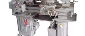
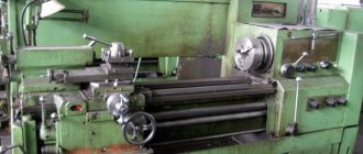
photo: lathe gearbox
The speed can be changed in a stepless or stepwise manner as well as reversing. Several methods are used for this, for example:
Gearbox device
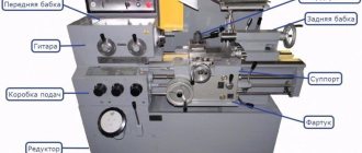
The gearboxes of metal-cutting machines can differ markedly from each other. Using the example of a device such as a 1M61 lathe, we can consider the components of the equipment. This includes things like:
Operating principle of the gearbox
The gearbox of a 16K20 lathe operates on a gear block. Switching of these blocks is carried out using a special handle, which transfers the gear from one area to another. The spindle head receives rotational motion of a given speed from the gears, which transmit this through a gear coupling. The handle turns the clutch on and off, thereby regulating the speed. The adjustment takes place in two directions, in which the lead screw rotates, so that you can increase and decrease the rotation speed with one control element.
Basic movements
The rotary cutter gearbox itself remains stationary during operation, but its internal parts, such as the belt drive, can move. Movements take place in the longitudinal plane, depending on where exactly the control handle is directed. Transmission moves from one sector to another, increasing or decreasing speed.
Adjusting the gearbox of a lathe
Gaps. With active use of equipment, gaps appear near moving parts over time. This not only reduces the accuracy of the equipment, but can also lead to breakdown. The machines provide for the adjustment of such connections, which consists of fixing the main fasteners in position at the proper distance. For this, wedges, nuts and bolts and other elements are used.
Clutch adjustment. One of the main elements that the 1K62 lathe gearbox has is the coupling located on its main shaft. Due to the friction that occurs during operation, its disks are subject to severe wear over time. To adjust it, use pressure nuts that are screwed onto the ring. After pressing the latch into the ring, you can turn the nuts until they stop. When the clutch is fully adjusted, it starts without jolts or sudden movements.
Backlash adjustment. If play appears during operation, it should be eliminated. To do this, you need to disassemble the box with the machine turned off, place the parts in the correct position and fix them. During operation, vibration will cause play to appear periodically and this is quite normal, so you should be careful to eliminate it in time.
Repair of lathe gearbox
Source
Types of gearboxes
A gearbox is a mechanism designed to stepwise change the frequency (speed) of rotation of the driven shaft at a constant speed, leading by changing the gear ratio. Changing the rotation speed is achieved by including various gear kinematic pairs between the shafts. The gearboxes must provide the calculated range of spindle rotation speeds in accordance with GOST 8032-56.
The gearboxes are compact, easy to operate and reliable in operation. The disadvantages of gearboxes include the difficulty or impossibility of stepless control of rotation speeds, the occurrence of vibration and noise at some frequencies. There are a large number of different designs of gearboxes, but they are all a combination of individual standard mechanisms.
According to the layout, the gearboxes are divided into gearboxes with gears built into the spindle headstock, and speedboxes with a separate drive, when the spindle headstock and the gearbox are made in the form of separate units connected by a belt drive.
According to the switching method, gearboxes are available with replaceable gears between the shafts and a constant center distance, with movable wheels or wheel blocks, with wheels and cam clutches that cannot be moved along the shafts, with friction clutches, with electromagnetic clutches and with combined switching. The gearboxes are made in a closed housing, the gears operate in an oil bath. This design protects the mechanisms from contamination, provides abundant lubrication and good cooling of the mechanisms, and increases the efficiency of the gearbox.
Feed box design for lathe 1k62
The purpose of the feed chain of a screw-cutting lathe is to ensure mechanical movement of the cutter mounted on the support relative to the rotating workpiece during turning. Modern universal screw-cutting lathes have a feed box , which is usually mounted on the bed below the headstock.
The feed box is used to switch the rotation speed of the lead screw and the lead shaft, i.e., to select the feed speed of the cutter along the spindle axis. For example, when cutting a metric thread with a pitch of 1 mm, the feed box mechanism must ensure that the cutter moves (feed) along the workpiece by 1 mm per spindle revolution.
Inside the feed box there is a gearbox, which consists of switchable gears. The input shaft of the feed box receives torque from the spindle through replaceable gears (guitar). At the output of the feed box there is usually a drive shaft and a lead screw, the torque from which is supplied to the caliper apron.
When cutting threads, the feed box transmits rotation to the lead screw; When turning and cutting face (flat) threads, a roller is used.
Using a lead roller for feed during turning allows you to maintain the accuracy of the lead screw longer, which is necessary when cutting threads.
Replacement gears (guitar) are used only when the required feed cannot be achieved by switching the feed box handles.
The source of movement (initial link) of the feed chain is the spindle, therefore the feed speed in screw-cutting lathes is measured and indicated in millimeters per spindle revolution (mm/rev).
The feed mechanism must allow:
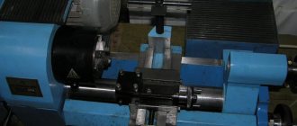
General view of the feed box assembly
Photo of the feed box
Main design features
A universal screw-cutting lathe consists of main structural units, which are standard elements. These include:
- caliper;
- bed;
- thrust and spindle headstock;
- electrical equipment;
- drive shaft;
- guitar gears;
- a box that provides selection and change of feeds;
- lead screw - it is this detail that distinguishes a screw-cutting lathe from a standard lathe.
Depending on some features, the accuracy of the machine may vary. Therefore, universal equipment can be of both accuracy class N and increased – P.
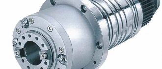
Front and rear stock
The headstock or spindle has the main role of fixing the workpiece in processing and transmitting rotation to the workpiece from the electric motor.
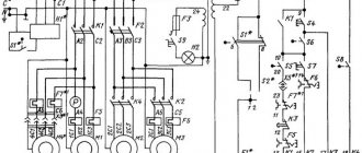
Kinematic diagram of screw-cutting lathe 1K62
The spindle is reversed by moving the coupling 97 to the right. Then the rotation from shaft II to shaft III is transmitted through gears 22-23, 24-12 and further along the previous chain. The number of gearing options is 15, the actual values of rotation speeds are 12, since the gear ratios of some options are also numerically the same.
Feeding movement . The feed mechanism includes four kinematic chains: screw-cutting, longitudinal and transverse feed, and a chain of accelerated movements of the caliper. Rotation to shaft VIII is transmitted from spindle V through gears 25-26, and when cutting threads with an increased pitch - from shaft VI through the step increasing link and then through gears 27-28. In this case, the step increasing link can provide four gear options:
Screw chain . When cutting threads, the caliper is fed from the lead screw 68 through the uterine nut fixed in the apron. For cutting metric and modular threads, the screw-cutting chain is installed according to the first option, and for inch and pitch threads - according to the second. Changing the thread pitch is achieved by switching the gears of the pitch increasing link, the Norton mechanism, blocks 61-63 and 67-66 and installing replacement wheels on the guitar. When turning and cutting metric and inch threads, replaceable gears 39-43-40 are in mesh, and when cutting modular and pitch threads - 41-43-42.
Feed box design of screw-cutting lathe 1K62
The headstock mechanism allows:
The feed box receives movement from the headstock output shaft through replaceable triplane gears.
The feed box mechanism allows you to obtain all types of threads and required feeds provided for by GOST.
Through a lead screw with a pitch of 12 mm (without a pitch increasing link), the following threads can be obtained:
Using the mechanism for increasing the pitch, at spindle speeds from 12.5 to 40, it is possible to obtain threads with an increased pitch (32 times greater than normal, and at speeds from 50 to 160, 8 times in accordance with the data in the table on handle 20 (see Fig. Fig. 5).
Through the running roller, the caliper at any number of spindle revolutions receives longitudinal feeds from 0.07 to 2.08 mm/rev and transverse feeds from 0.035 to 1.04 mm/rev, and at speeds from 50 to 630 per minute, longitudinal feeds from 2. 28 to 4.16 mm/rev and transverse from 1.14 to 2.08 mm/rev.
To cut more precise threads in the feed box, the position of the handle 19 is provided in which the lead screw is engaged directly, bypassing the feed box mechanism. In this case, the required pitch is selected using interchangeable gears of a special set.
By turning handle 20, the choice of a number of threads or feeds is selected. To obtain the required value from the selected row of threads or feeds, you need to pull the drum disk towards you by the handles, turn until the notches of the disk coincide with the notch of the drum, and then move the disk forward to its previous position
To carry out rapid movements of the caliper, an overrunning clutch is mounted in the feed box on the output shaft.
Rice. 7. Directions for transmitting motion through the feed box when cutting various threads and providing longitudinal and transverse feeds.
Feed drive
The feed motion is borrowed from the spindle shaft (VI) through the 60/60 guitar gears. Further, from VII to VIII shaft, the movement is transmitted through a reversing mechanism (42/42 or 28/56 or 35/28/35). From shaft VIII to shaft IX, movement is transmitted through replaceable gears (42/95/50 or 64/95/97). Wheel 35 rotates together with shaft IX, from which the movement branches into two directions (see Fig. 7): in the first direction, rotation is transmitted when cutting inch and pitch threads, and in the second direction, metric, modular and providing longitudinal and transverse feeds.
The first direction of rotation transmission . Clutch M2 is disengaged and from wheel 35 the movement is transmitted through wheels 37/35 to shaft X, from which the captive mobile block of wheels 25–36 receives rotation through wheels 28/25. Wheel 36 of this block can be meshed with any wheel of a seven-speed block of 16 gears (Norton cone) (48,44,40,36,32,28,26), which in turn will lead to rotation of shaft XI, and with it the wheel 35 (clutch M3 is turned off at this time). Next, the movement is transmitted by wheels 35/28, 28/35 (two wheels 28 are mounted on a common bushing, but they do not transmit rotation to shaft XIII - they rotate freely on the shaft). Clutch M4 is turned off (it connects the rotation of shafts X and XII when transmitting rotation in the second direction). From wheel 35, rotation is transmitted to shaft XII, together with which the wheel block 18–28 rotates. From shaft XII to shaft XIII, motion can be transmitted through 18/45 or 28/35 wheels. Next, a pair of 35/28 or 15/48 wheels is used from shaft XIII to shaft XIV. Shaft XIV is connected to shaft XVI when the M5 coupling is engaged and, thus, the lead screw t = 12 mm receives rotation.
Second direction of rotation transmission . clutch M2 is engaged, at the same time wheel 35 located on shaft X is disengaged, and the seven-speed gear block receives rotation. From this block, the movement is transmitted to the coupling block of wheels 36–25, then to shaft X through wheels 25/28, while the M4 clutch is engaged (when the right coupling half is moved to the left, wheels 35 and 28 are disengaged) and therefore shaft XII rotates integrally with the shaft X. Next, the movement is transmitted in the same way as described above: from shaft XII to shaft XIII, and from there to shaft XIV. Moreover, when cutting metric and inch threads 17, the rotation in the guitar is transmitted through replaceable gears 42/95/50, and when cutting modular and pitch threads, the replaceable blocks are turned over and then the rotation will be transmitted through gears 64/95/97. When cutting threads, the movement is transferred to the lead screw, and to obtain longitudinal and transverse feeds, the M5 clutch is disconnected and the XV shaft receives rotation through the 28/56 double-crown wheels and the Mo overrunning clutch. When wheels 28–28 are shifted to the left, its left gear rim engages with wheel 56, rigidly mounted on shaft XV, and rotation is transmitted to the latter in addition to the overrunning clutch, which is necessary when cutting end threads.
Lubrication system
The location of lubrication points is shown in Fig. 26. Table 5 contains a list of system elements and lubrication points.
Description of the lubrication system
Careful attention to lubrication and normal operation of lubrication systems are a guarantee of trouble-free operation of the machine and its durability.
The machine has two isolated centralized lubrication systems:
- gear wheels, gearbox bearings and gearbox elements;
- gears, feed box bearings, console, slides, console guides, slides and table.
The oil reservoir and gearbox lubrication pump are located in the frame. Oil is poured into the reservoir through cover 5 to the middle of oil indicator 9. If necessary, the oil level must be replenished. The oil is drained through pipe 6.
The operation of the gearbox lubrication system is monitored by oil indicator 7.
The oil reservoir and lubrication pump for the units that provide the feed movement are located in the console. Oil is poured into the reservoir through elbow 2 to the middle of oil indicator 1. It is not recommended to exceed this level: filling above the middle of the oil indicator can lead to oil leaks from the console and feed box. In addition, when the reservoir is overfilled, oil flows through the racks into the gearbox housing, which can lead to damage to the limit switch for short-term activation of the feed motor. When the oil level drops to the lower point of the oil indicator, the reservoir must be refilled. Oil is drained from the console through plug 3 at the bottom of the console on the left side. The operation of the lubrication system of the feed box and console is monitored by oil indicator 10.
The operation of the lubrication system is considered satisfactory if oil flows out of the supply tube in drops; the presence of a trickle or filling of the indicator niche with oil indicates good operation of the oil system.
The guides of the table, slide, console and longitudinal drive mechanisms located in the slide are periodically lubricated by a pump located in the console. The oil to lubricate these components comes from the console reservoir. The console guides are lubricated from button 11, and the guide slides, table and longitudinal drive mechanisms are lubricated from button 12.
The sufficiency of lubrication is assessed by the presence of oil on the guides.
Lubrication should be carried out taking into account the degree of loading of the machine, as a rule, before work (approximately twice a shift for a duration of 15-20 seconds.
The end support bearings (point 4) of the longitudinal feed screw are lubricated by extrusion.
Step #5. Rapid feed of lathe
There are combined feeds of lathes (by type of drive, by direction). Such lathes are used for processing non-critical cones (irresponsible chamfers) and shaped surfaces.
Threaded feeds
To cut threads, the caliper is fed by closing the master nut with the lead screw. Turning the uterine nut on and off is done with a separate lever. The spindle and lead screw rotate synchronously, regardless of the set thread pitch. Changing the direction of rotation of the spindle leads to a change in the direction of movement of the caliper. Also, changing the spindle speed leads to a change in the speed of movement of the caliper. The entry of the cutter into a previously cut groove is ensured by synchronizing the rotation of the spindle and lead screw and, accordingly, the travel of the caliper.
You can cut both right-handed and left-handed threads using a switch on the headstock, which changes the direction of movement of the screw relative to the spindle. When cutting threads, it is not recommended to get carried away with high spindle speeds, since its rotation is directly related to the movement of the caliper.
Overview and diagrams of common models
Among the diverse model range and several generations of machines that are produced by our production, there are several models that continue to be popular for their technical characteristics and universal properties.
All of them are used in production or in domestic conditions to this day. At the same time, they continue to be worthy competitors to foreign analogues.
These are reliable, durable and durable devices capable of performing a huge number of different functions.
1L532
One of the most popular machines in the former USSR, which can successfully process workpieces of medium and large sizes.
At one time, this equipment was successfully exported to many countries around the world. Accuracy class – N. Machine weight – 43 tons.
16U04P
High precision equipment. The largest diameter of the part processed above the bed is 200 mm. Machine weight – 750 kg.
1P611
A machine used in production, including for turning wheels of railway vehicles. According to GOST, they are distinguished by increased accuracy and have the ability to brake the spindle. Device weight 560 kg. Easily performs the following functions:
- Drilling.
- Segment.
- Cutting internal and external threads.
- Treatment of various surfaces.
The largest diameter of the workpiece above the bed is 250 mm.
1D601
This machine is better suited for purely domestic use. The accuracy is lower than the previous machine. It features high performance even after many years of operation.
Moving the caliper is only possible manually. The weight of the entire machine is about 30 kg. Due to the small dimensions, the maximum length of the workpiece to be processed is 18 cm.
16K40
One of the most popular models that has really gained popularity among craftsmen. Belongs to the middle class of equipment with accuracy class N.
Since 1932, several tens of thousands of various screw-cutting lathes have been produced in the USSR. They were used not only in production, but also for training young people, in schools, colleges, and many had desktop machines in garages, homes, and their own workshops.
Such equipment will help to bore a hole, level the required surface, or drill an existing hole. It is important, focusing on the initial specifications of the equipment, to purchase the most suitable model.
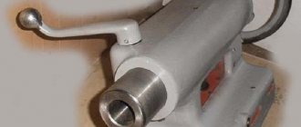
Tailstock control of a lathe
Fixing the tailstock of a lathe is done with a lever, and as the working stroke progresses, the clamping force increases. When processing heavy loads that require better fixation by the tailstock, the action on the lever must be vigorous. It is important not to confuse the resistance of the lever when clamping with its rigid stop at the end of the stroke. When the tailstock is used with minimal loads, its maximum fixation with the bed is not necessary. It is rational to measure the tailstock clamp with the upcoming load.
The tailstock quill is driven by manual feed by rotating the flywheel. The tools and accessories are secured in the quill cone in the following order:
Toolholder control
The tool holder is a fairly precise mechanism that ensures rigidity of the tool attachment in specified positions. The correct position of the tool holder handle when clamped should correspond to the clockwise position at 3-4 o'clock. This position is ensured by the position of the spacer washer under the nut of the tool holder handle. The lever is clamped with an average elbow force. And pressing the handle cannot be done using your own weight to avoid weight loss. Squeezing the handle is done with one or more short pushes with the heel of the palm in a counterclockwise direction. Before rotating the tool holder, make sure there are no obstructions to the tool holder or the tool attached to it. Obstacles from the rotating elements of the machine pose a great danger.