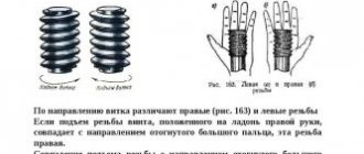
Multi-start thread. Basic Concepts
To obtain a strong screw with a large pitch, multi-start threads are used. In this case, the pitch, height of the thread and its internal diameter correspond to a single-start thread, and the thread stroke is as many times greater than the pitch as there are starts; for example, for a two-start thread the stroke is twice as large as its pitch (see Fig. 320, b), for a three-start thread (see Fig. 320, c) it is three times larger, etc.
Single-start and multiple-start threads
With a single-start thread, the pitch and thread stroke are the same, and for one revolution of the screw the nut moves by the pitch amount. If the movement of the nut per revolution should be large, then the stroke, and therefore the pitch of the single-throw screw, should be large. The larger the pitch, the deeper the thread (the height of the thread depends on the pitch) and the smaller the internal diameter of the screw. A screw with a small internal diameter is not strong enough and cannot transmit large forces.
There are many examples of the use of multi-start threads: eyepieces in binoculars and microscopes, ballpoint pen caps, lids for glass jars, etc.
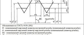
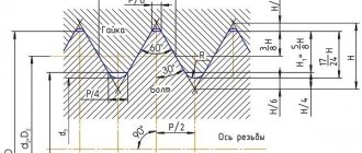
TOLERANCE FIELDS
9.1. The tolerance fields of external and internal threads established in accuracy classes (fine, medium and coarse) must correspond to those indicated in Table 6.
Table 6
| Accuracy class | External thread | Internal thread | ||
| Make-up length | ||||
| Tolerance field | ||||
| Accurate | 7e, 7g | 8e | 7N | 8H |
| Average | 8s, | 9s | 9N | |
| Rude | 9s | 10s | 9N | 9N |
Notes:
1. With increased accuracy requirements for make-up lengths, it is allowed to use the tolerance fields established for make-up lengths.
2. Boxed tolerances are preferred.
9.2. The tolerance fields of external and internal threads indicated in Table 6 are a restrictive selection from the entire set of tolerance fields that can be obtained by various combinations of degrees of accuracy according to Table 2 and main deviations according to Table 3.
Tolerance fields not provided for in Table 6 are special. Their use is allowed in technically and economically justified cases, if the tolerance fields according to Table 6 cannot meet the requirements for the product.
9.3. The maximum deviations of external and internal threads corresponding to the tolerance fields established in Table 6 are given in GOST 9562 and Appendix 2.
9.4. In landings, any combination of tolerance fields for external and internal threads established by this standard is allowed. It is preferable to combine tolerance fields of the same accuracy class.
Multi-start thread. GOST and basic parameters
Multi-start threads are manufactured in accordance with GOST 24739-81, which establishes nominal diameters, pitches, strokes and tolerances for the trapezoidal profile of multi-start threads. There are also metric and involute multi-start threads, but they are not regulated.
Stroke and pitch of trapezoidal double-start thread
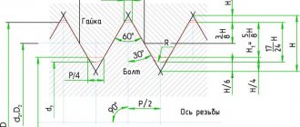
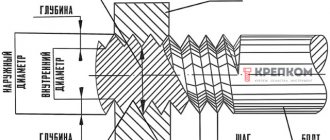
Basic concepts and parameters in the process of cutting multi-start threads:
- d is the outer diameter (nominal) of the external thread (screw);
- P - thread pitch;
- n is the number of thread starts;
- Ph is the thread lead, defined as Ph = P ∙ n .
Metric Thread Size Chart
ISO Metric Thread Chart:
| Metric ISO Profile | External thread | |||||
| Threads | Main diameter | Step diameter | Small diameter | |||
| Step size | Maximum | Minimum | Maximum | Minimum | Maximum | Minimum |
| M 2 x 0.4 | 1.981 | 1.886 | 1.721 | 1.654 | 1.548 | 1.408 |
| M 2.2 x 0.45 | 2.18 | 2.08 | 1.888 | 1.817 | 1.693 | 1.54 |
| M 3 x 0.5 | 2.98 | 2.874 | 2.655 | 2.58 | 2.439 | 2.272 |
| M 8 x 1.25 | 7.972 | 7.76 | 7.16 | 7.042 | 6.619 | 6.272 |
| M 12 x 1.75 | 11.97 | 11.7 | 10.83 | 10.68 | 10.072 | 9.601 |
| M 16 x 2 | 15.96 | 15.68 | 14.66 | 14.5 | 13.797 | 13.271 |
| M 20 x 2.5 | 19.96 | 19.62 | 18.33 | 18.16 | 17.252 | 16.624 |
| M 24 x 3 | 23.95 | 23.58 | 22 | 21.8 | 20.704 | 19.955 |
| M 30 x 3.5 | 29.95 | 29.52 | 27.67 | 27.46 | 26.158 | 25.306 |
| M 36 x 4 | 35.94 | 35.47 | 33.34 | 33.12 | 31.61 | 30.654 |
| M 48 x 5 | 47.93 | 47.4 | 44.68 | 44.43 | 42.516 | 41.351 |
| M 60 x 5.5 | 59.93 | 59.37 | 56.35 | 56.09 | 53.971 | 52.7 |
| M 80 x 6 | 79.92 | 79.32 | 76.02 | 75.74 | 73.425 | 72.047 |
| M 100 x 6 | 99.92 | 99.32 | 96.02 | 95.72 | 93.425 | 92.027 |
ISO Metric Thread Table 2:
| Metric ISO Profile | Internal thread | |||||
| Threads | Small diameter | Step diameter | Main diameter | |||
| Step size | Maximum | Minimum | Maximum | Minimum | Maximum | Minimum |
| M 2 x 0.4 | 1.679 | 1.567 | 1.83 | 1.74 | 2.148 | 2 |
| M 2.2 x 0.45 | 1.838 | 1.713 | 2.003 | 1.908 | 2.36 | 2.2 |
| M 3 x 0.5 | 2.599 | 2.459 | 2.775 | 2.308 | 3.172 | 3 |
| M 8 x 1.25 | 6.912 | 6.647 | 7.348 | 7.188 | 8.34 | 8 |
| M 12 x 1.75 | 10.441 | 10.106 | 11.063 | 10.863 | 12.453 | 12 |
| M 20 x 2.5 | 17.744 | 17.294 | 18.6 | 18.376 | 20.585 | 20 |
| M 30 x 3.5 | 26.771 | 26.211 | 28.007 | 27.727 | 30.785 | 30 |
| M 60 x 5.5 | 54.796 | 54.046 | 56.783 | 56.428 | 61.149 | 60 |
| M 80 x 6 | 74.305 | 73.505 | 76.478 | 76.103 | 81.241 | 80 |
| M 100 x 6 | 94.305 | 93.505 | 96.503 | 96.103 | 101.27 | 100 |
Multi-start thread. Designation
The symbol for a trapezoidal multi-start thread should include: the letters Tr, the nominal diameter of the thread, the numerical value of the stroke and in brackets the letter P and the numerical value of the pitch, the letters LH for left-handed threads.
An example of a symbol for a trapezoidal multi-start thread with a nominal diameter d=20 mm, a numerical stroke value Ph=8 mm and a pitch P=4 mm:
Tr20×8 (P4)
Symbol for left-hand thread:
Tr20×8 (P4) LH
The tolerance field of a multi-start trapezoidal thread consists of the designation of the tolerance field of the average diameter, i.e. a number indicating the degree of accuracy and a letter indicating the main deviation.
The tolerance field 4h of diameter d and the tolerance field 4H of diameter d1 are not indicated in the thread symbol.
The make-up length , if different from the thread length, is indicated in millimeters at the end of the thread designation, for example:
Tr80×40 (P10)-8e-180
The designation of a metric multi-start thread begins with the letter M. An example of the designation of a thread with a nominal diameter d=16 mm, stroke Ph=3 mm, and a pitch of 1.5 mm and a tolerance range of 6h:
M16×Ph 3 P1.5-6h
MAIN DIMENSIONS
3.1. The nominal diameter, stroke, pitch and number of thread starts must correspond to those indicated in the table. .
Table 1
Dimensions in mm
| Nominal thread diameter d | Step P | Number of visits n | |||||
| 2 | 3 | 4 | 6 | 8 | |||
| Row 1 | Row 2 | Thread stroke R h | |||||
| 10 | 1,5 | 3 | 4,5 | 6* | 9* | 12* | |
| 2 | 4 | 6* | 8* | 12* | 16* | ||
| 12 | 2 | 4 | 6 | 8* | 12* | 16* | |
| 3 | 6* | 9* | 12* | 18* | — | ||
| 16 | 2 | 4 | 6 | 8 | 12* | 16* | |
| 4 | 8* | 12* | 16* | 24* | — | ||
| 20 | 2 | 4 | 6 | 8 | 12* | 16* | |
| 4 | 8 | 12* | 16* | 24* | 32* | ||
| 24 | (2) | 4 | 6 | 8 | 12 | 16* | |
| 3 | 6 | 9 | 12 | 18 | 24 | ||
| 5 | 10 | 15* | 20* | 30* | — | ||
| 8 | 16* | 24* | 32* | — | — | ||
| (2) | 4 | 6 | 8 | 12 | 16* | ||
| 3 | 6 | 9 | 12 | 18* | 24* | ||
| 28 | 5 | 10 | 15* | 20* | 30* | 40* | |
| 8 | 16* | 24* | 32* | — | — | ||
| 32 | 3 | 6 | 9 | 12 | 18* | 24* | |
| 6 | 12 | 18 | 24* | 36* | 48* | ||
| 10 | 20* | 30* | 40* | — | — | ||
| 3 | 6 | 9 | 12 | 18 | 24* | ||
| 36 | 6 | 12 | 18 | 24* | 36* | 48* | |
| 10 | 20* | 30* | 40* | — | — | ||
| 40 | 3 | 6 | 9 | 12 | 18 | 24* | |
| (6) | 12 | 18 | 24* | 36* | 48* | ||
| 7 | 14 | 21* | 28* | 42* | 56* | ||
| 10 | 20* | 30* | 40* | 60* | — | ||
| 44 | 3 | 6 | 9 | 12 | 18 | 24* | |
| 7 | 14 | 21 | 28* | 42* | 56* | ||
| (8) | 16 | 24* | 32* | 48* | 64* | ||
| 12 | 24* | 36* | 48* | — | — | ||
| 48 | 3 | 6 | 9 | 12 | 18 | 24 | |
| 8 | 16 | 24 | 32* | 48* | 64* | ||
| 12 | 24* | 36* | 48* | 72* | — | ||
| 3 | 6 | 9 | 12 | 18 | 24 | ||
| 50 | 8 | 16 | 24 | 32* | 48* | 64* | |
| 12 | 24* | 36* | 48* | 72* | — | ||
| 52 | 3 | 6 | 9 | 12 | 18 | 24 | |
| 8 | 16 | 24 | 32* | 48* | 64* | ||
| 12 | 24 | 36* | 48* | 72* | — | ||
| 3 | 6 | 9 | 12 | 18 | 24 | ||
| (8) | 16 | 24 | 32* | 48* | 64* | ||
| 55 | 9 | 18 | 27 | 36* | 54* | 72* | |
| (12) | 24 | 36* | 48* | 72* | — | ||
| 14 | 28* | 42* | 56* | 84* | — | ||
| 60 | 3 | 6 | 9 | 12 | 18 | 24 | |
| (8) | 16 | 24 | 32* | 48* | 64* | ||
| 9 | 18 | 27 | 36* | 54* | 72* | ||
| (12) | 24 | 36* | 48* | 72* | 96* | ||
| 14 | 28 | 42* | 56* | 84* | — | ||
| 4 | 8 | 12 | 16 | 24 | 32 | ||
| 70 | 10 | 20 | 30 | 40* | 60* | 80* | |
| 16 | 32* | 48* | 64* | 96* | — | ||
| 80 | 4 | 8 | 12 | 16 | 24 | 32 | |
| 10 | 20 | 30 | 40 | 60* | 80* | ||
| 16 | 32 | 48* | 64* | 96* | 128* | ||
| 4 | 8 | 12 | 16 | 24 | 32 | ||
| (5) | 10 | 15 | 20 | 30 | 40 | ||
| 90 | 12 | 24 | 36 | 48* | 72* | 96* | |
| 18 | 36 | 54* | 72* | 108* | 144* | ||
| (20) | 40 | 60* | 80* | 120* | — | ||
| 100 | 4 | 8 | 12 | 16 | 24 | 32 | |
| (5) | 10 | 15 | 20 | 30 | 40 | ||
| 12 | 24 | 36 | 48 | 72* | 96* | ||
| 20 | 40 | 60* | 80* | 120* | 160* | ||
| 120 | 6 | 12 | 18 | 24 | 36 | 48 | |
| 14 | 28 | 42 | 56 | 84* | 112* | ||
| (16) | 32 | 48 | 64* | 96* | 128* | ||
| 22 | 44 | 66* | 88* | 132* | 176* | ||
| (24) | 48 | 72* | 96* | 144* | 192* | ||
| 6 | 12 | 18 | 24 | 36 | 48 | ||
| 140 | 14 | 28 | 42 | 56 | 84* | 112* | |
| (16) | 32 | 48 | 64 | 96* | 128* | ||
| 24 | 48 | 72 | 96* | 144* | 192* | ||
| 160 | 6 | 12 | 18 | 24 | 36 | 48 | |
| (8) | 16 | 24 | 32 | 48 | 64 | ||
| 16 | 32 | 48 | 64 | 96* | 128* | ||
| (24) | 48 | 72 | 96* | 144* | 192* | ||
| 28 | 56 | 84* | 112* | 168* | 224* | ||
| 8 | 16 | 24 | 32 | 48 | 64 | ||
| 18 | 36 | 54 | 72 | 108* | 144* | ||
| 180 | (20) | 40 | 60 | 80 | 120* | 160* | |
| 28 | 56 | 84 | 112* | 168* | 224* | ||
| (32) | 64 | 96* | 128* | 192* | 256* | ||
| 200 | 8 | 16 | 24 | 32 | 48 | 64 | |
| (10) | 20 | 30 | 40 | 60 | 80 | ||
| 18 | 36 | 54 | 72 | 108* | 144* | ||
| (20) | 40 | 60 | 80 | 120* | 160* | ||
| 32 | 64 | 96 | 128* | 192* | 256* | ||
| 8 | 16 | 24 | 32 | 48 | 64 | ||
| (10) | 20 | 30 | 40 | 60 | 80 | ||
| 220 | 20 | 40 | 60 | 80 | 120* | 160* | |
| (32) | 64 | 96 | 128* | 192* | 256* | ||
| 36 | 72 | 108 | 144* | 216* | 288* | ||
| 240 | 8 | 16 | 24 | 32 | 48 | 64 | |
| 22 | 44 | 66 | 88 | 132* | 176* | ||
| 36 | 72 | 108 | 144* | 216* | 288* | ||
| 12 | 24 | 36 | 48 | 72 | 96 | ||
| 250 | 22 | 44 | 66 | 88 | 132 | 176* | |
| (24) | 48 | 72 | 96 | 144* | 192* | ||
| 40 | 80 | 120 | 160* | 240* | 320* | ||
| 12 | 24 | 36 | 48 | 72 | 96 | ||
| 260 | 22 | 44 | 66 | 88 | 132 | 176* | |
| 40 | 80 | 120 | 160* | 240* | 320* | ||
| 280 | 12 | 24 | 36 | 48 | 72 | 96 | |
| 24 | 48 | 72 | 96 | 144 | 192* | ||
| 40 | 80 | 120 | 160* | 240* | 320* | ||
| 12 | 24 | 36 | 48 | 72 | 96 | ||
| 300 | 24 | 48 | 72 | 96 | 144 | 192* | |
| 44 | 88 | 132 | 176* | 264* | 352* | ||
| 320 | 12 | 24 | 36 | 48 | 72 | 96 | |
| 48 | 96 | 144 | 192* | 288* | 384* | ||
Notes:
1. Boxed steps are preferred.
2. The steps indicated in parentheses are not recommended for use when developing new designs.
3. A thread with a stroke value marked * has a lead angle of more than 10°. For this thread, it is necessary to take into account the deviation of the profile shape in accordance with clause 4.5.
4. Threads for which the numerical value of the stroke P
h, is not allowed. The helix angle of this thread exceeds 30°.
5. In technically and economically justified cases, it is allowed to use other values of nominal thread diameters in accordance with GOST 24738.
When choosing thread diameters, you should prefer the first row to the second.
3.2. The nominal dimensions of the outer, middle and inner thread diameters are in accordance with GOST 24737.
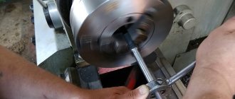
Multi-start thread. Methods for cutting multi-start threads on a lathe
The main problem when cutting multi-start threads is the placement of the cutter at the beginning of the next thread pitch. To accurately position the cutter at the beginning of the next step, several techniques are used:
- Rotation of the workpiece using replaceable gears;
- Rotation of the workpiece using a special driving dividing chuck with several grooves;
- Rotation of the workpiece using a special dividing chuck;
- Division into multi-start threads on a screw-cutting lathe 1k62;
- Division into multi-start threads on a screw-cutting lathe 16k20;
- Division by pitch using the screw of the upper slide of the caliper;
- Division by pitch using thread cutting indicator;
- Simultaneous cutting of multi-start threads with several cutters;
- Simultaneous cutting of multi-start threads with a cutting comb.
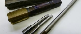
4.1. Cutting multi-start threads using replaceable gears
Replaceable gears
When dividing using replaceable gears , it is necessary that the first driving replaceable wheel has a number of teeth that is divisible without a remainder by the number of thread starts, for example, by three for a three-start thread. Having cut the first turn of the thread, mark with chalk (Fig. 332): mark 3 in the middle of the tooth of the first drive wheel z1 and mark 4 against the corresponding cavity of the tooth of the second wheel z2. Count from mark 3 the required number of teeth of the first wheel (for a two-start thread, half, for a three-start thread, a third, etc.) The corresponding tooth is marked with mark 2. After this, remove the first replaceable drive wheel from the roller and turn the spindle until when putting on the wheel z1 tooth with notch 2 will not coincide with notch 4 (wheels z2, z3 and z4 remain stationary). After this, the wheels are engaged again and the second turn of thread is cut. Before cutting the third turn, repeat the described division technique; risk 1 must match risk 4.
4.2. Cutting multi-start threads using a special driver dividing chuck
Drive dividing chuck
The multi-slot driving chuck makes it much easier to accurately turn the workpiece. The number of grooves must be equal to the number of screw strokes or be a multiple of this number. After cutting the first turn of the thread, the caliper is returned to its original position without opening the master nut, the workpiece is removed from the centers and placed again on them so that the clamp fits into the next groove of the driving chuck. Then cut the second thread.
4.3. Cutting multi-start threads using a special dividing chuck
Drive dividing chuck
A special driving dividing chuck (Fig. 333.) also greatly facilitates the division of multi-start threads into starts. The cartridge consists of two disks 2 and 3, connected by two bolts 1 and 5; on one disk 2 there is a mark, and on the second 3 there is a scale in degrees. Having cut one turn of thread, the caliper is returned to its original position without disconnecting the mother nut, disk 3 with driver 4 and the part are rotated relative to the stationary mark by 360°/2 = 180° when cutting a two-start thread, by 360°/3 = 120° when cutting a three-start thread threads, etc.
This division method is used for parts that can be processed in centers; It is not suitable for work in a jaw chuck.
4.4. Division into multi-start threads on a 1K62 screw-cutting lathe
Dividing into multi-start threads on a 1k62 machine occurs by rotating the workpiece to the desired angle, as in previous cases.
To facilitate division, the machine has special options:
- 1. Disconnecting the spindle from the feed box while turning the spindle with the workpiece. To do this, the handle for setting the increased-normal thread pitch must be set to the “Division into multi-start threads” position.
- 2. Disc on the back of the spindle with divisions marked in degrees
Thus, the machine can cut multi-start threads divided into 2, 3, 4, 5, 6, 10, 12, 15, 20, 30 and 60 starts.
To divide into multi-start threads it follows (from the instructions for the 1k62 machine):
- 1. Stop the main electric motor;
- 2. Turn on the forward friction clutch;
- 3. Remove the case covering the replacement gears and drive belts;
- 4. Rotate the friction shaft counterclockwise until the marks “60” on disk 1 (Fig. 18) coincide with the mark on flange 7. After this, you need to remove the tension in the chain;
- 5. Set the gearbox handle 3 (the handle for setting the increased, normal thread pitch and position when dividing into multi-start threads) (see Fig. 5) to the position “Dividing into multi-start threads”
- 6. Turn the friction shaft counterclockwise when dividing into a two-start thread by 30 divisions on the disk, a three-start thread by 20, a four-start thread by 15, etc.
- 7. Set the gearbox handle 3 to the position corresponding to thread cutting.
4.5. Division into multi-start threads on a 16K20 screw-cutting lathe
Division into multi-start threads on a 16k20 machine is carried out in exactly the same way as on 1k62.
When cutting multi-start threads, you should (from the instructions for the 16k20 machine):
- 1) Handles 8 and 16 must be in the middle positions (friction clutch control handles);
- 2) Use handle 15 to turn on the lead screw nut;
- 3) Using handles 1 and 2, according to the table placed on the spindle head, set the required number of spindle revolutions, and handles 5 and 7 - the required value of the pitch of the thread being cut;
- 4) By manually turning flange 24 (spindle with workpiece) (Fig. 14 and 17), align the arrow pointer on it with one of the marks of the spindle dividing ring 240, indicated by some number;
- 5) When cutting threads with pitches within metric and modular from 0.5 to 7, inch and pitch from 56 to 4, disengage the spindle from the kinematic chain of the machine for dividing by the number of passes by setting handle 3 to the position marked with a special symbol indicating spindle shutdown. For the remaining thread pitches, disengagement is carried out by turning handle 1 from a fixed position to the nearest intermediate position, marked with a similar symbol;
- 6) division by the number of starts is done by manually turning the spindle by the number of notches corresponding to the number of starts of the thread being cut (with two starts - 30 notches, with three - by 20, with four - by 15, etc.);
- 7) set handle 1 or 3 to its original position;
 Cut the thread;
- 9) upon subsequent division, repeat the operations outlined in paragraphs 5-8 in a similar way.
4.6. Division by step
Dividing multi-start threads by pitch offset
Pitch division is the simplest and fastest method of dividing multi-start threads available in a single production environment.
This method is as follows. First, cut the first turn of the thread. Having cut it, remove the cutter from the groove with a transverse feed towards you and give the lead screw a reverse motion, returning the cutter to its initial position without opening the nut.
To enter the second turn, move the cutter in the longitudinal direction by a thread pitch, but not with the lead screw, but with the screw of the upper slide of the caliper. The longitudinal movement of the cutter is measured along the screw dial of the upper slide, if the screw and nuts of the upper slide are in good working order.
For more accurate installation of the cutter, indicator devices and a set of measuring tiles are used. So, to cut a two-start thread, the cutter should be moved to Ph/2, to cut a three-start thread - to Ph/3, a four-start thread - to Ph/4, etc.
4.7. Pitch-by-pitch division using thread cutting indicator
Threading indicator (on indicator)
The main disadvantage of dividing multi-start threads into starts by turning the workpiece is accelerated wear of the master nut and a decrease in productivity, since after each working pass the caliper returns to its original position without opening the master nut until threading is completed. That is, at the end of each pass, you need to move the cutter away from the part, stop the machine, reverse it, stop again in its original position, give the cutter a transverse or lateral feed for a new pass and repeat the cycle. Thus, the support remains in a rigid kinematic connection with the machine spindle all the time and the cutter cannot help but fall into the thread pitch.
Another method is to mark the position of the spindle relative to the frame and the support relative to the lead screw before turning the machine into operation. At the end of each pass, the mother nut is released and returned to its original position manually or using a rapid feed mechanism. To re-engage (close) the uterine nut, you need to re-align the relative position marks.
Threading indicator (on indicator)
The best results are obtained by using a special device called a threading indicator (power indicator) , which is installed in the supports of most modern machines.
At the start of threading, the threading indicator should be attached to the apron and engaged with the machine lead screw.
It is necessary to set the cutter to the initial cutting position, align it with the desired indication line on the indicator and start the machine for turning the thread. After each completed pass, the lead nut of the lead screw can be opened, and the longitudinal slide returns accelerated or by a flywheel to its original position.
If the required thread cannot be made in one pass, it is necessary to realign the starting position of the thread and the indication line and repeat the pass. This way the required thread will be cut.
The next turn, if the thread is multi-start, must be made offset by one step from the initial cutting position.
Setting the Thread Cutting Indicator to the desired mode should be carried out according to the instructions for the specific model of the indicator and machine.
4.8. Simultaneous cutting of multi-start threads with several cutters
When cutting multi-start threads simultaneously with several cutters installed in special holders, division is ensured automatically. When cutting double lead screws, use a tool holder (Fig. 18, c), in which two cutters are fixed. They are installed according to a template at a distance exactly corresponding to the step between passes. Thus, both cutters cut two grooves at the same time. Obviously, to process a three-start thread, three cutters could be installed in the same way.
Cutting double threads with two cutters
4.9. Simultaneous cutting of multi-start threads with a cutting comb
Using multi-profile threaded dies. In this case, all thread starts are cut simultaneously. The thread progress is ensured by the feed of the caliper, the pitch is ensured by the pitch of the comb.
The second and third methods are the most productive. Their use is limited:
- the need for sufficient space for the exit of the cutter block or comb;
- significant deformations due to multi-cutting;
- the difficulty of accurately manufacturing blocks and dies.