Design and operating characteristics of the main components of the machine
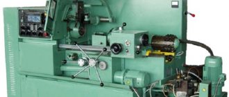
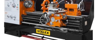
General view and layout of the 1K62 machine (Fig. 1)
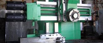
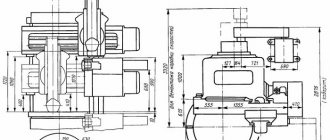
The main components of the machine: bed 13, which serves to connect all components of the machine; headstock 2, which houses the spindle 4 of the machine and the gearbox; a support 11 on which the cutting tool is fixed; tailstock 15; feed box 3, transmitting rotation to the lead shaft 24 and the lead screw 23; cabinet 20 with electrical equipment of the machine; stands 22 and 29.
The machine bed 13 (see Fig. 1, a) rests on the left 29 and right 22 pedestals, to which it is rigidly fastened. The left cabinet contains the electric motor of the main drive of the machine. The right cabinet contains a pump that supplies coolant through a hose to the cutting tool. Liquid flows from trough 27 into the internal cavity of the cabinet. The most accurate position of the moving units of the machine is ensured by the combined frame guides - prismatic a and flat b (Fig. 1, b).
Headstock 2 is bolted to the left side of the frame. The inner part of the headstock contains a spindle 4 and a gearbox, covered with a lid on top.
If necessary, a rod processed on the machine can be passed through the through hole of spindle 4, and the front center can be installed in the conical socket of the spindle. At the right protruding end of the spindle there is a centering belt, a shoulder and a thread for precise alignment and fastening of the faceplate with chuck 5, into the cams of which the workpieces are installed.
The support 11 is designed to move the cutting tools attached to it and consists of the following main parts: a carriage 6, an apron 25, a transverse slide 7, a middle rotating part 8, an upper slide 10 and a quadruple tool holder 9 for installing and securing cutting tools.
Carriage 6 moves in the longitudinal direction along prismatic a and flat b guides (Fig. 1, b). Planks 1 and 2 of the carriage slide along the lower guides d and c. The carriage is moved manually in the longitudinal direction by rotating the flywheel 26 (Fig. 1, a).
The apron 25 is rigidly fixed to the carriage 6. It contains mechanisms that convert the rotational movement of the roller 24 and the screw 23 into the translational movement of the caliper.
To eliminate backlash in the screw drive, the screw nut consists of two parts, which are moved apart with a wedge. The middle part 8, together with the guides of the upper slide 10 located on it, which can be rotated relative to the axis of the machine at an angle and mounted on the transverse slide 7, is intended for processing conical surfaces of products.
The upper slide 10 is designed to move the cutter manually when rotating the handle 12. The exact amount of movement of the caliper is manually measured using dials with a division value of 0.05 mm
Feed box 3 serves to transmit rotation to the lead roller 24 or lead screw 23. The feed box is connected to the machine spindle by a transmission, which includes a set of interchangeable wheels located under the shield 1.
The tailstock 15 is designed to support the workpieces being processed with its rear center or to install and move axial tools. The main parts of the tailstock: plate 17, body 16, quill 14, clamping bar 1 (Fig. 1, c).
The tailstock moves along prismatic a and flat b guides (Fig. 1, c) of the machine bed. The movement is carried out either manually or using a caliper - if the tailstock is connected to it with a lock (Fig. 1, d). The lock consists of a bar 2 attached to the cross slide 1, a caliper and a bar 4 connected to the tailstock plate 3. By bringing the caliper to the tailstock and moving the slide 1 in the transverse direction, the protrusion of the bar 2 is inserted behind the protrusion of the bar 4. In this case, the tailstock is connected to the caliper and together with it will move in the longitudinal direction from the feed mechanism.
In order for the top of the rear center to be accurately located on the axis of the machine, the body 16 (Fig. 1, a) is moved in the transverse direction relative to the plate 17. To process conical surfaces of parts, the rear center is shifted with a screw 19 from the axis of the machine in the direction “toward” or "Push". Quill 14 has a tapered hole for mounting rear center or axial tools.
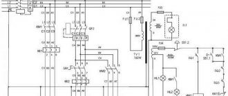
The electrical equipment of the machine is located in cabinet 20. On the front wall of the cabinet there is a panel 18 with an ammeter indicating the current of the main electric motor of the machine, and switches that turn on the machine to the electrical network, machine lighting and the electric motor of the pump supplying coolant.
Under cover 21 there is an electric motor for rapid movement of the caliper.
What is a CNC machine?
Humanity has always loved to create means of production. With the development of human society, the means of production became more and more advanced. Each era leaves its mark, and one of the most significant achievements of the 20th century - the transistor revolutionized metalworking. For the first time in the history of mankind, it became possible to mass produce parts, practically* without human intervention.
*To an inexperienced reader, it may seem that CNC machines do everything themselves. Actually this is not true. Behind the already established program lies the enormous and meticulous work of highly qualified specialists.
So, let's start with the basics. The abbreviation CNC stands for numerical control, or in English - computer numerical control (CNC). A machine equipped with a CNC rack can be considered as a classic machine, in which the movement of the cutting tool is controlled by a computer according to a pre-written program. In addition, the machine has auxiliary devices that allow you to automate the process of processing parts.
The main advantages of CNC machines:
— High-precision processing of parts - most CNC machines can process parts with an accuracy of 0.01 mm.
— Increasing the degree of automation of production - the machine can process workpieces without human intervention. It is only necessary to change the workpieces and monitor the wear of the cutting tool. Well, write and set up a program.
— High speed of processing parts - thanks to electric axle drives, the operating speed of movements on a CNC machine can reach 3000 mm/min.
The main disadvantages of CNC machines:
— The high cost of the machine means you have to pay for convenience. The cost of an ordinary CNC machine can start from 1 million rubles (as of 2021).
— Complex design of a CNC machine – to ensure the machine is in good working order, it is necessary to carry out timely maintenance.
— Long changeover time – producing only a few units of products on CNC machines is usually not profitable. The changeover time to a new part can take about 1 hour.
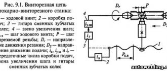
Kinematic diagram of screw-cutting lathe 1K62
Kinematic diagram of a screw-cutting lathe 1k62
Movements in the machine: main - main movement, longitudinal and transverse feeds of the support; auxiliary - quick movements of the caliper, tailstock and quill manually.
Kinematic chain of the main movement drive. This chain ensures the transmission of rotation from the electric motor M1 to spindle VI with the ability to switch on different frequencies of its rotation (Fig. 2). The machine spindle can have a right or left direction of rotation. When the spindle rotates to the right, the balance equation for the kinematic chain of the main motion drive will be written as follows (clutch Mf1 is turned to the left) (Fig. 2, a):
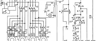
The headstock is conventionally divided into several parts (see kinematic diagram):
- Friction (input) shaft - the friction shaft consists of: a double friction clutch Mf1 with a fixed double block (z=51, z=56), a gear (z=50) and a fixed reverse block (z=24, z=36);
- Gearbox - shaft II with a movable double block (B1), shaft III with a movable triple block (B2);
- Bust - shaft IV with movable double blocks (B3, B4, B5);
- Brake unit - band brake on shaft III;
- Spindle - with a movable double block (B5) including busting and a gear z=60 for transmitting rotation to the feed drive;
- Feed drive unit:
- The thread pitch increasing link - block B6, provides an increase in the output speed in relation to the spindle speed;
- The reverse mechanism is 2-speed - block B7 is used to change the direction of movement of the caliper.
Speed graph of screw-cutting lathe 1k62
With the direct (right) direction of spindle rotation, the balance equation of the kinematic chain of the main motion drive will be written as follows (clutch Mf1 is turned to the left). 24 rotation speeds can be set in the range of 12.5...2000 rpm (frequency 630 rpm repeats).
Balance equation for the forward (right) direction of spindle rotation
In the reverse (left) direction of spindle rotation, the balance equation of the kinematic chain of the main motion drive will be written as follows (clutch Mf1 is turned to the left). 12 rotation speeds can be configured in the range of 19..2420 rpm.
Balance equation for the reverse (left) direction of spindle rotation
Kinematic chain of cutting motion of a screw-cutting lathe 1k62
Where:
1450 — number of revolutions of the electric motor;
142/254 — transmission ratio of the belt drive (ratio of the diameters of the engine pulleys (Ø 142) and the gearbox (Ø 254));
0,985 — coefficient of elastic slippage of the belt drive.
What types of CNC machines are there?
There are a lot of CNC machines and they all have different designs. Let's break down the variety of CNC machines into fundamental categories:
Semi-automatic devices. These are machines that operate according to a specific algorithm; usually, setting them up involves adjusting the mechanical components of the machine and adjusting the response time of the actuators. It is not difficult to learn how to use such machines. They usually have an intuitive interface and detailed operating instructions. They do not have CNC racks, but are equipped with an operator panel on which the basic parameters of the machine are selected and the processing cycle is started. Semi-automatic machines are usually:
- Grinding machines
- Cutting machines
- Bending machines
- Forging and pressing equipment
- Guillotine shears
2-D processing machines. These are machines that process flat parts. Basically, the movement of the cutting tool is carried out along two axes. It is possible to add an axis for changing the angle of the tool, which allows you to cut parts with conical surfaces. Often, programming such machines comes down to creating a two-dimensional contour of a part and processing it in a specialized CAM system that comes with the machine. These machines include:
- Waterjet cutting
- Plasma cutting
- Gas cutting
- Erosion processing machines
- Punching machines
3-D processing machines. This category includes all machines that allow processing of a three-dimensional part. Setting up such machines can take much longer. Sometimes a team of several people may participate in the setup and maintenance of such machines. The program for such machines can be written in different ways, both in a CAM system and on a CNC rack.
- Lathes
- Milling machines
- 3d printers
- Rotary drawing machines
- Engraving machines
As you can see, there are a lot of machines that are controlled by a computer. They all have their own characteristics. The most common are lathes and milling machines. We will tell you about them in more detail. They, in turn, can be divided into woodworking machines and metalworking machines. The design of a CNC machine for metal is much more complex, and that is what we will talk about.
Feed movement
The feed drive includes the following chains and components (see kinematic diagram):
- Thread pitch increasing link - double block B6 in the spindle head, provides an increase in the output rotation speed in relation to the spindle speed in the ratio: 1:2, 1:8, 1:32
- The 2-speed reverse mechanism is a triple block B7 in the spindle head, used to change the direction of movement of the caliper with the same direction of spindle rotation. It is carried out by connecting the intermediate gear - snaffle;
- Guitar of replacement wheels - includes replacement gears K, L, M, N. Serves for relatively rare reconfiguration of speeds;
- Feed Box - The feed box receives movement from the headstock through the guitar and sets different rotation speeds for the lead shaft and lead screw;
- Apron feed mechanism - converts the rotation of the lead shaft or lead screw into longitudinal or transverse movement of the caliper.
Feed box for screw-cutting lathe 1k62
Kinematic chain of longitudinal feeds of the caliper
The longitudinal movement of the caliper is carried out as follows:
from the spindle through a 60/60 gear, then through the reverse with wheels 42/42 or 28/56 or 35/28•28/35 and through a set of interchangeable wheels 42/95•95/50, the IX feedbox shaft rotates.
Having connected the clutch, the MF2 wheel begins to rotate the cone of gears 26, 28, 32, 36, 40, 44, 48 and from it the union wheel 36.
Next, through the gear and the engaged MF3 clutch, the double block z = 18 – z = 28 rotates, realizing the ratios 18/45 and 28/35, then through the double block 15/48 and 35/28 and through the gear 28/56 the running shaft rotates, according to to which the wheel z = 27 moves together with the apron.
Further, the movement is transmitted through the gear ratios of the apron wheels 27/20 • 20/28 • 4/20 • 40/37 • 14/66 to the rack wheel z = 10 (engagement module m = 3 mm). Wheel 10, being in engagement with a rail attached to the frame, rolls along it and moves the apron with the caliper.
By turning on the MF8 or MF9 clutches, the wheel z = 14 rotates to the right or left, changing the direction of movement of the caliper. The general equation of the kinematic chain of longitudinal feeds is determined based on the calculated period of one spindle revolution:
General equation of the kinematic chain of longitudinal feeds of the 1k62 machine
The limits of the longitudinal feed values when the corresponding blocks are turned on are 0.07...0.13; 0.14…0.26; 0.28…0.52; 0.57…1.04; 1.14…2.08; 2.28…4.16 mm/rev. The last group of feeds is obtained by turning on the thread pitch increasing link.
Kinematic chain of transverse caliper feeds
Up to the worm gear of the apron, the kinematic chain does not differ from the previous chain. Next, through the wheels 40/37 or 40/45•45/37, by turning on the MF10 or MF11 couplings, and through the gears 40/61•61/20, the caliper transverse feed screw rotates. The screw thread pitch is 5 mm, left-hand thread. The equation of the kinematic chain is similar to that for longitudinal feeds. The feed values are 2 times less than the corresponding longitudinal values and range from 0.035 to 2.08 mm/rev.
Manual longitudinal movement of the caliper. The flywheel on shaft XIX rotates the rack wheel z = 10 through a gear. For one revolution of the flywheel, the caliper will move by an amount
1 • 14/66 • π • 10 • 3 = 20 mm
Kinematic chain for producing metric threads
The settings for the screw-cutting chain must be calculated and adjusted in such a way that the amount of longitudinal movement of the caliper per one revolution of the spindle exactly corresponds to the pitch T of the thread being cut.
When cutting threads to move the caliper, a lead screw with a pitch of 12 mm is used. For this purpose, the wheel block z = 28 – z = 28 engages with the MF5 coupling. The uterine nut, closed with the screw, moves along with the apron and caliper. The kinematic chain does not differ from the longitudinal feed chain, but the apron transmission is not involved. The equation of the kinematic chain in this case is determined based on the following: for one revolution of the spindle, the support with the cutter must travel a path equal to the pitch of the thread being cut, and will be written in this form:
Kinematic chain for producing metric threads
where Tn.r. – pitch of the thread being cut.
In this chain, the gear cone B10 (26, 28, 32, 36, 40, 44, 48) is the driving one.
Not all wheels, when meshed with the cap wheel z = 36, give the standard steps, for example, for the Tn.r. step. = 1 mm the cone wheel z = 32 is involved, as can be seen from the equation of the kinematic chain
An example of a kinematic chain for obtaining metric threads
Thread pitch increasing link
The gearbox has a link for increasing the thread pitch. To obtain increased thread pitches, it is necessary to move the double block z = 60 – z = 45 of shaft VII to the right until the wheel z = 45 of this block engages with the wheel z = 45 of shaft III. Then the number of shaft revolutions relative to the spindle will be increased by 16 or 4 times, while the spindle should rotate through a 27/54 gear.
Then all other gears and the lead screw will rotate at an accelerated rate of 32, 8 or 2 times, depending on the inclusion of blocks z=88 - z=45 and z=22 - z=45 on shaft IV. Largest thread pitch Tn.r. = 192 mm with bit ratio iTP = 28/56.
Kinematic chain for producing modular threads
The modular thread pitch is proportional to π – Тн.р. = π•m (m – engagement module in mm). The kinematic chain is carried out similarly to the chain for metric threads, but in the guitar of replacement wheels it is necessary to install wheels 64/95 • 95/97.
The equation of the kinematic chain will be written as follows:
Kinematic chain for producing modular threads
To obtain large modular threads, a link is used to increase the thread pitch and mmmax = 48 mm.
Kinematic chain for producing inch and pitch threads
Inch thread is characterized by the number of threads per 1″. The kinematic chain is recorded in the same way as for a metric thread, but the gear cone is driven, for which the MF2 coupling is disconnected from the wheel z = 35, and the MF4 and MF3 couplings are turned off.
The general equation of the kinematic chain will be:
Kinematic chain for producing inch and pitch threads
Limits on the number of threads of the thread being cut: Tn.r. = 2…24 threads per 1″. Pitch threads, which are characterized by pitches, are very rarely used. Pitch value p = 25.4/m. The kinematic chain is the same as for the inch one, but the replacement wheel guitar has 64/95 • 95/97 wheels. Limits of p values: 7...96, and for smaller values a link for increasing the thread pitch is used.
Kinematic chain for cutting particularly precise threads
These threads are cut by turning on the lead screw, bypassing the feed box, thereby shortening the kinematic chain. To do this, it is necessary to connect the lead screw to the IX shaft of the feed box by turning on the couplings MF2, MF4, MF5 and disconnecting the wheel block z=25 and z=36 from the cone in the feed box.
The equation of the kinematic chain in this case will be written as follows:
1 • 60/60 • 42/42 • x • 12 = Tn.r.; hence x = Tn.r./12
where x is the gear ratio of replacement wheels, consisting of one or two pairs.
CNC milling machine structure:
Figure 7. Basic elements of a CNC vertical milling machine.
A milling machine is a machine used for processing workpieces using a rotating tool (cutter). In this case, the workpiece is installed on the machine table, and the axes perform a feed movement. The cutter is fixed in the machine spindle. A classic milling machine has three linear axes: X-longitudinal axis Y-transverse axis Z-vertical axis. Additional rotary axes can be installed on the milling table.
Figure 8. Milling machine axes
Milling machines allow you to process trunnions, pockets, planes and chamfer along the contour of the part. They can be used to drill holes in workpieces and cut threads.
The basis of a milling machine will always be the bed. A column and a transverse Y axis are attached to the frame. A slide is attached to the movable Y axis. On which, in turn, the longitudinal X axis is installed. A work table is mounted on the X axis guides, on which the workpieces to be processed are mounted.
The Z-axis guides and the tool changer are mounted on the column. The tool changer is fixed on the column, so the Z coordinate for tool change will be fixed. The Z axis can move vertically. The machine spindle is mounted on the Z axis, with the help of which the workpiece is milled
How does a CNC machine work?
Let's look at how programming CNC machines is carried out, in particular, using the same algorithm, programming CNC machines with a FANUC rack is carried out:
Creating a program:
- It all starts with the details. Technologists, based on the requirements for the part and its shape, select the necessary machine for its manufacture. In general, there can be several machines. But in our example, we assume that the part is made only on a CNC milling machine. The technologist also develops recommendations on how to process the part - at what cutting modes and with what tool.
- Then the workpiece zero point is determined. This will determine how the service technician will attach the tool to the workpiece and from what point the program will be written.
The programmer determines the sequence of processing the part. If the sequence was chosen incorrectly, the part will not be made. There are obvious and not obvious mistakes. For example, it is obvious that it is impossible to cut threads without first drilling holes. But non-obvious errors are revealed only during processing. This is very expensive and you have to rewrite the program. An example of a non-obvious error is the initial execution of operations that reduce the rigidity of the machine, after which it will be problematic to finish the part.
- Then a suitable workpiece is selected with the necessary allowances for processing and fastening. The workpieces must be fairly similar, otherwise the program will take longer to complete due to the need to process large allowances for individual workpieces.
- A programmer writes a program for a CNC machine. The installer writes the program into the memory of the CNC machine.
Setting up a program on a CNC machine:
- The service technician places the required tool and assigns its coordinates.
- The workpiece is fixed on the machine, and the operator sets the zero of the workpiece, according to the program
- The installer runs the program in frame-by-frame mode, at the minimum rapid feed. Particular attention is paid to places in the program where rapid traverse and tool changes are used. It is necessary to ensure that the chips are well removed from the cutting site and that the coolant supply system is configured correctly.
- After running the program, the geometric parameters of the parts are measured. In case of deviation from the required parameters, corrections must be made to the tool offset or program text.
- Once the correct geometric parameters have been achieved, parts can be manufactured automatically. The operator is already doing this.
- When automatic processing is running, the operator must constantly monitor the operation of the machine. There is always the possibility of tool breakage and chip accumulation.