Brief history of the series
Two years later, in 1934, production of such models as the DIP-300, DIP-400, DIP-500 lathe was launched.
By 1937, special types of nomenclature and sizes were being developed. A unified system of symbols is adopted. Thus, the first machine produced by the plant was named 1D62, but the abbreviation DIP-20 was retained.
The year 1940 was marked by the creation of the 162K 26A machine, as one of the versions of the DIP-200.
Then various modernized machines were produced, and in 1948, the legendary 1A62 appeared. The models were produced in large quantities.
And finally, in 1971, the first prototype of the 16 to 20 machine was manufactured. The machine even received a gold medal at the fair in ’72.
From 1972 to 1973, reconstruction was carried out at the plant, this is due to the large-scale production of new 16K20 models. The company is developing mass production of this model, and at the end of 1973, the monthly production turnover reaches 1 thousand copies. About 10% of the total is exported.
Then various modifications of the 16 to 20 model appeared, including 16 K 25, 16 K2 0M, 16 K2 0P, 16 K 20V, 16 K 20G, 16 K 20K, 16K20F1, 16K20PF1, 16K20VF1 and others. All were based on the basic standards of the 16 to 20 model.
1988 will mark the end of production of machines of this model. It was replaced by the MK series.
Main varieties and explanation of modifications
This model has four varieties, but the general kinematic scheme is:
- 16K20 – standard turning-screw-cutting model;
- 16K20P - screw-cutting lathe with increased accuracy;
- 16K20G - screw-cutting lathe has normal accuracy and a recess in the bed;
- 16K25 is a lightweight model of a screw-cutting lathe with a center height of 250 mm.
The numbers and letters in the machine name indicate the following:
- The number “1” indicates the corresponding group to which the machine belongs (this is a universal turning-screw-cutting model, according to the generally accepted Russian classification ENIMS).
- The number “6” describes the subgroup (lathe-screw-cutting in this case).
- The letter “K” is the decoding of the plant that manufactured the machine and the designation of the generation.
- The number “20” indicates the center height of 220 mm.
Technological route for spindle repair
When checking the spindle (Fig. 27), it was found that:
- surface runout 2 - [Ø50k6]1 is 0.04 mm
- surface runout 6 — [Ø70k6] — 0.06 mm
- surface bead runout 6 - 0.06 mm
- surface wear 1 - [M48]x1.5 is 0.4 mm per side
- surface wear 2 - Ø49.96 mm [Ø50k6]
- surface wear 3 - Ø59.95 mm [Ø60k6]
- surface wear 4 - [M64]x6 - thread jammed 0.3 mm per side
- surface wear 5 - Ø74.97 mm [Ø75k6]
- surface wear 6 - Ø69.87 mm [Ø70k6]
- surface wear 7 - [M68]x2 - thread jammed 0.35 mm per side
- surface wear 8 - nadirs and nicks up to 0.8 mm
- surface wear 10 - 6.07 mm [6j86]
- surface wear 11 - 6.07 mm [6j86]
1 The nominal dimensions of the spindle (before wear) are indicated in square brackets
To perform spindle repairs, you must have the following equipment:
- screw cutting lathe
- vertical milling machine
- cylindrical grinding machine
- repaired machine with a spindle installed on it
- workbench with bench vice
- galvanic bath
Specifications
Basic machine parameters
- With the largest processing diameter of the bed - 400 mm.
- With the largest caliper processing diameter - 220 mm.
- Distance between centers -1500 mm.
- Spindle bore - 51 mm.
- Spindle speed - 12.5-1600 rpm 24 steps.
- Power supply - 415 volts / 50 Hz / 3 phase.
- Heavy-duty screw-cutting lathe.
- Made in Russia.
- One-piece cast base.
- Pneumatic floating tail stock.
- Saddle lube.
- Metric configuration.
- Halogen work lamp.
- Reserve for mechanical protection of the cartridge.
- Protects the tailstock, lead screw and feed shaft.
- Cooling system.
Spindle
Acts as a hollow, multi-stage shaft made of steel, heat treated to increase durability.
The spindle has a steel structure and a longitudinal hole inside, it allows the workpiece to pass through. The spindle itself rotates thanks to specialized precision bearings. They are wear-resistant and precise in manufacture, and do not require frequent maintenance.
Caliper and feed
This is the part of the machine used to hold the tool and allows longitudinal and lateral movement of the tool.
This machine block is very rigid, which reduces the possibility of errors caused by elastic deformation of the sliding system during cutting.
Cutting slide
The slides are needed to adjust the thread engagement; they move in the longitudinal direction. The cutting head is attached to them.
Tailstock
Used to clamp a rotating cutting tool and as an additional support, used with rotating and non-rotating centers for hard cutting.
Electrical equipment
Thanks to electrical equipment, maximum protection of the worker is ensured, protecting him from electric shock. And the unit itself is protected from damage.
What does electrical equipment consist of:
- Main electric motor.
- An electric motor that moves the caliper and carriage.
- Electric pump with coolant system.
- Automatic shutdown systems.
- Fuses.
- Thermal relay.
- Grounding.
- Microswitch.
Dimensions and weight
Dimensions (L x D x H) - 3200 mm x 1300 mm x 1900 mm;
Weight (approximately) - 3000 kg.
Technical characteristics of the lathe 16K20
| Parameter name | 16K20 | 16K20P |
| Basic machine parameters | ||
| Accuracy class according to GOST 8-82 | N | P |
| The largest diameter of the workpiece installed above the bed, mm | 400 | 400 |
| Height of the center axis above the flat guides of the frame, mm | 215 | 215 |
| The largest diameter of the workpiece processed above the support, mm | 220 | 220 |
| Maximum length of the workpiece installed in the centers (RMC), mm | 710, 1000, 1400, 2000 | 710, 1000 |
| The greatest distance from the axis of the centers to the edge of the tool holder, mm | 225 | 225 |
| The largest diameter of the drill when drilling steel parts, mm | 25 | 25 |
| Maximum mass of workpiece processed in centers, kg | 460..1300 | 460..1300 |
| Maximum mass of workpiece processed in the chuck, kg | 200 | 200 |
| Spindle | ||
| Spindle hole diameter, mm | 52 | 52 |
| The largest diameter of the rod passing through the hole in the spindle, mm | 50 | 50 |
| Spindle rotation speed in forward direction, rpm | 12,5..1600 | 12,5..1600 |
| Spindle rotation speed in reverse direction, rpm | 19..1900 | 19..1900 |
| Number of forward spindle speeds | 22 | 22 |
| Number of spindle reverse speeds | 11 | 11 |
| Spindle end according to GOST 12593-72 | 6K | 6K |
| Tapered spindle bore according to GOST 2847-67 | Morse 6 | Morse 6 |
| Spindle flange diameter, mm | 170 | 170 |
| Maximum torque on the spindle, Nm | 1000 | 1000 |
| Caliper. Submissions | ||
| Maximum length of longitudinal movement, mm | 645, 935, 1335, 1935 | 645, 935 |
| Maximum length of transverse movement, mm | 300 | 300 |
| Speed of fast longitudinal movements, mm/min | 3800 | 3800 |
| Speed of fast transverse movements, mm/min | 1900 | 1900 |
| Maximum permissible speed of movement when working on stops, mm/min | 250 | 250 |
| Minimum permissible speed of movement of the carriage (support), mm/min | 10 | 10 |
| Price for dividing the longitudinal movement dial, mm | 1 | 1 |
| Transverse movement dial division price, mm | 0,05 | 0,05 |
| Longitudinal feed range, mm/rev | 0,05..2,8 | 0,05..2,8 |
| Transverse feed range, mm/rev | 0,025..1,4 | 0,025..1,4 |
| Number of longitudinal feeds | 42 | 42 |
| Number of cross feeds | 42 | 42 |
| Number of threads to be cut - metric | ||
| Number of threads to be cut - modular | ||
| Number of threads cut - inch | ||
| Number of threads to be cut - pitch | ||
| Limits of metric thread pitches, mm | 0,5..112 | 0,5..112 |
| Limits of pitches of inch threads, threads/inch | 56..0,5 | 56..0,5 |
| Limits of modular thread pitches, module | 0,5..112 | 0,5..112 |
| Limits of pitch thread pitches, diametric pitch | 56..0,5 | 56..0,5 |
| The greatest force allowed by the feed mechanism on the cutter is longitudinal, N | 5884 | 5884 |
| The greatest force allowed by the feed mechanism on the cutter is transverse, N | 3530 | 3530 |
| Cutting slide | ||
| Maximum movement of the cutting slide, mm | 150 | 150 |
| Movement of the cutting slide by one division of the dial, mm | 0,05 | 0,05 |
| Maximum angle of rotation of the cutting slide, degrees | ±90° | ±90° |
| Scale division of the tool slide rotation scale, deg | 1° | 1° |
| The largest cross-section of the cutter holder, mm | 25 x 25 | 25 x 25 |
| Height from the supporting surface of the cutter to the axis of the centers (cutter height), mm | 25 | 25 |
| Number of cutters in the cutting head | 4 | 4 |
| Tailstock | ||
| Tailstock quill diameter, mm | ||
| Cone of the hole in the tailstock quill according to GOST 2847-67 | Morse 5 | Morse 5 |
| Maximum movement of the quill, mm | 150 | 150 |
| Movement of the quill by one division of the dial, mm | 0,1 | 0,1 |
| The amount of lateral displacement of the headstock body, mm | ±15 | ±15 |
| Electrical equipment | ||
| Main drive electric motor, kW | 11 | 11 |
| Electric motor for fast movement drive, kW | 0,12 | 0,12 |
| Coolant pump electric motor, kW | 0,125 | 0,125 |
| Dimensions and weight of the machine | ||
| Machine dimensions (length width height) RMC=1000, mm | 2795 x 1190 x 1500 | 2795 x 1190 x 1500 |
| Machine weight, kg | 3010 | 3010 |
General design and operating principle
The design of a screw-cutting lathe is a large unit consisting of a large number of components, which includes electrical equipment, supports, feed box, spindle and tailstock.
Important!
The design provides for a number of protective elements, blocking and fencing, ensuring safe interaction with the device.
It works on the principle of a universal lathe that performs a number of different jobs, and some non-standard operations using additional equipment, for example, threading, drilling, etc.
Purpose and main areas of application
Designed to perform all basic types of turning work, as well as perform non-standard operations when using additional devices, for example, it is possible to perform a forge operation of twisting (torsing) square bars for the manufacture of balusters.
Produced in the former Soviet Union since 1971 at the Krasny Proletary enterprise. For a long time, the 16K20 was the main screw-cutting lathe of the Soviet, and subsequently Russian, mechanical engineering. It is now out of production, and the Belarusian machine GS526U can claim a worthy replacement for it, the technical characteristics and weight of which are as close as possible to its legendary prototype, but significantly improved: modern technical and technological solutions were introduced into the design, modern materials were used in the production of machine parts, the main components were redesigned taking into account the shortcomings of the predecessor.
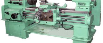
16K20 general view
Machine in the workshop
16K20 with a distance between centers of 1500 mm
By the way, the weight of 16K20 is less than the weight of its predecessor model 1K62.
This machine is universal and is designed for machining parts that are installed in a three- or four-jaw chuck or in centers. The equipment allows you to perform work in a manual cycle with optimal accuracy, while maintaining occupational safety.
16K20 is used in single and serial production of mechanical engineering enterprises, tool production, mechanical repair shops, etc. for finishing and semi-finishing of parts.
Operating manual and machine passport
Specifications
Technical characteristics of the 16K20 machine may vary depending on the modification and manufacturer.
Characteristics of 16K20
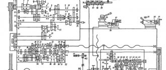
Kinematic diagram
The kinematic diagram shows the relationships between the main components and elements of the machine.
As with all lathes, the main movement is the rotation of the spindle, which is transmitted from an electric motor through a V-belt drive and gearbox.
The support moves in the longitudinal and transverse directions. The feed mechanism transmits movement to the caliper along 4 kinematic chains, and also allows for threading.
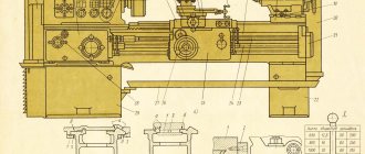
Photo and description of the machine device
Below are schematic images of the most important components of the machine and a brief description of them.
General form
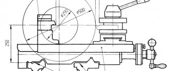
Drawing
The drawing shows the working area of the machine, the location and distance of all significant parts of the equipment.
Location of controls
The numbers on the diagram indicate the location of the following controls:
- Handle that sets the feed amount and thread.
- A handle responsible for the type of work: feed and type of thread.
- A handle that sets the number of spindle revolutions.
- A handle that sets an increased thread pitch.
- Input circuit breaker.
- Signal lamp.
- Pump switch.
- Load indicator.
- Handles adjusting right and left threads.
- A handle that sets a series of rotation numbers.
- The handle that regulates the friction clutch in the main drive.
- Workplace lighting switch.
- Handles that rotate and secure the indexable cutting head.
- The handle that moves the cutting slide.
- Handles securing the tailstock to the frame body.
- The flywheel that moves the tailstock.
- Handle that regulates the friction clutch.
- A handle that turns the lead screw off and on.
- A handle that controls the mechanical movement of the carriage and slide.
- A push-button station that turns the electric motor on and off.
- A handle that moves the cross slide of the caliper.
- A flywheel that establishes manual movement of the carriage.
- Button, carriage guide and cross slide.
- A handle that sets the feed and pitch for the thread.
Kinematic diagram
The kinematic diagram is used to understand the connection and interaction between the main elements of the machine.
Headstock
The spindle head can set numbers in 4 rows, two rows with limits of 40, 50 and 160 rpm, two rows with limits of 200, 630 and 500.
Gearbox
Ensures the movement of the cutter and tool on the machine guides at a given speed. This part is used to set a constant feed speed when cutting or other work.
With a gearbox inside, consisting of a switchable gear train. Using the input shaft, it receives torque from the spindle assembly. With lead screw, shaft on feed box.
Apron
The apron is a part responsible for the accuracy of feeding into the caliper. It has mechanisms that protect and ensure reliability and safety during operation.
The apron is located in the body, next to the caliper carriage. Provides rotational movements of the lead screw and transmits them to the caliper.
Caliper
It is a unit that secures a tool manually or automatically. The support contains a tool holder and a slide.
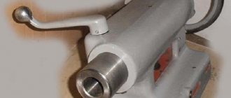
Tailstock
If, when retracting handle 19, sufficient pressure on the tailstock is not provided, it is necessary to change the adjustment of screws 26 and 33 in order to change the clamping bar.
If you need to install the tailstock transversely to the spindle, you need to align screws 41 with the flat surface A.
Instructions for first start-up and operation
Before the first start, you need to check the external reliability parameters and the stability of the unit installation. Having completed the inspection, it is worth turning off the power for each electric motor and using the input circuit breaker F1 into the workshop network.
All locking devices must comply with the data specified in the instructions:
- The main drive rotates counterclockwise towards the shaft.
- The electric pump rotates according to the indicated diagram on the housing.
- The hydroelectric power station rotates towards the fan, clockwise.
- The quick traverse motor rotates clockwise.
Important!
Check the operation of the magnetic starter and relay. After checking the correct operation of each electrical device, reconnect the previously disconnected wires. After a complete check of the electric motor, you can begin to work.
Operating and maintenance rules, machine passport
- The purpose of the machines is to use them in small-scale and single-piece production.
- The temperature in the workshop should be maintained at 30 degrees.
- Humidity control no more than 80%.
- Maintaining the quality and durability of the unit directly depends on the operating conditions; the accumulation of dust and the appearance of scales is unacceptable.
- Cast iron parts cause increased wear of the rubbing part; careful removal of chips and dust is required during processing.
- Moving parts are lubricated in a timely manner.
- A device left for a long period must be covered.
You can download the passport of the 16K20 screw-cutting lathe for free in pdf format from the link: Passport 16K20
Passport data of screw-cutting lathe 16K20
All topics in this section:
For specialty 150411 “Installation and technical operation of industrial equipment”
Explanatory note Guidelines for the course project in the discipline “Installation, maintenance and repair of industrial equipment” were compiled for students of specialty 150411 “Installation and technical equipment”
Requirements for the preparation of an explanatory note An explanatory note must contain all sections specified in the assignment. It is drawn up in compliance with the general requirements for text documents established in accordance with
Requirements for the design of the graphic part The graphic part is made on sheets of drawing paper in A1 format (594x841 mm) in full compliance with the current ESKD standards (GOST 2.301 - 68). Sheets of the graphic part of the course project d
Defects of parts Students provide data on the results of defects, justify the defect detection method and select control and measuring equipment. The results of defect detection are entered into the list of defects (attached
Determining a method for repairing a part To correctly select a method for repairing a part, it is necessary to correctly assess the type and degree of wear on the surfaces of the part. With an increased percentage of surface wear, the part is considered
Selection of the initial workpiece and its design A workpiece is a production item from which a part or one-piece assembly unit is made by changing the shape and dimensions, material properties and surface roughness -
GOST 26645-85, mm 1 class. accuracy 2 class. accuracy 3 grades. accuracy Nominal size, mm
Development of a route for mechanical processing of workpiece surfaces. The plan for processing workpiece surfaces determines the construction of a technological processing route. The types and sequence of processing required for each surface depend on its shape, accuracy and
Design of machining operations One of the tasks of optimizing the technological process of manufacturing a part is the selection of advantageous machining modes for each operation, i.e. for the processing process
Assigning the depth of cut taking into account the amount of allowance for processing When roughing, it is advisable to assign a depth of cut corresponding to cutting off the allowance in one pass. The number of passes in excess of one during roughing should be allowed as an exception.
G) Type of turning Depending on the type of turning, the conditions in which the cutter operates also change. During transverse turning (end trimming), the conditions for the cutter are more favorable than during longitudinal turning; when boring -
Milling with cylindrical cutters When assigning a cutting mode, the depth of cut is selected depending on the processing allowance and the required surface cleanliness. In most cases, the depth of cut when roughing milling machines is
Determining the standard time Auxiliary installation time is selected depending on the weight of the part and the nature of the installation, and the time associated with the transition is selected on the nature of the passage. Great value when milling
Milling with End Mills and Disc Mills 1. Milling with Disc Mills The depth of cut depends on the amount of allowance or groove depth and the cleanliness of the surface. According to the accepted cutting depth, diameter and number of teeth
Determination of the time standard The technical standard of piece-calculation time is composed of the time spent on production or repair and in the general case is determined by the formula Tshk =
Determination of the time standard The technical standard of piece-calculation time is composed of the time spent on production and is determined by the formula Tshk = To + Tv
Passport data of the vertical drilling machine 2N135 Motor power: Ndv = 4.5 kW; Machine efficiency ŋ =0.8; Spindle speed: 31.5; 45; 63; 90; 125; 180; 250; 355; 500; 710; 1000; 1440. (mi
Thread cutting design Cutting triangular threads In repair production on screw-cutting lathes, triangular threads are usually cut with taps, dies or a cutter. Cutting p
Cutting rectangular and trapezoidal threads The dimensions of rectangular threads are not standardized. When cutting rectangular threads with a pitch of up to 4 mm, one cutter is used, the profile of which must strictly correspond to the profile of the thread. carving
Cutting gear teeth using the copying method The copying method involves shaping the cutting tool into the cavity between the teeth. By sequential processing with this tool, wheel teeth are formed on the workpiece.
Cutting gears using the rolling method The essence of the rolling method is that the cutting tool is given the shape of a hob cutter, cutting gear or rack with cutting edges and a module equal to the module of the gear being cut
Cutting cylindrical gears When cutting cylindrical gears, the hob cutter is installed at a certain angle to the wheel being cut, so that the threads of the worm cutter coincide with the depressions
Cutting splined shafts and sprockets Splines of splined involute connections differ from the teeth of conventional spur gears only in their dimensions. Splined straight-sided shafts can be processed in repair shops
Selection of cutting modes Cutting modes when processing spline shafts with an involute profile are assigned in the same way as when cutting spur gears with worm cutters. Feed when cutting straight
Gear shaping work Gear shaping work is performed on gear shaping machines, mainly with a vertical spindle. The cutting tool in this case is a gear - a cutter, having a module identical to the
Gear-planing work Cutting bevel gears with straight teeth is carried out in several ways. The most widely used method in repair factories is the method of cutting with two toothed cutters according to the method
The course project is carried out in the following volume No. Name of the design task % of completion
List of defects for ____ overhaul_______ repairs _____________________________________________________ name of equipment inventory number No.______
Tolerance fields according to the CMEA system Shafts Holes OST system CMEA system OST system CMEA T1 system
Modern analogues
It has already been mentioned that the plant stopped producing the 16 to 20 model, so the selection of machines with similar characteristics is relevant. Foreign manufacturers are famous for the D420x1000, Proma SPC-900PA, Jet GH-1640ZX DRO units.
Belarusian analogues produced at the Gomel plant offer 16VT20P-21. You can also note the TRENS models from the Slovak manufacturer SN 50 C and SN 500 SA.
They have a modern design and high-quality German components, with a relatively low cost for their characteristics.
Prices for goods from other manufacturers start from one and a half million to two, without calculating the delivery and installation of units.