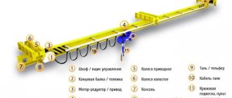
The crane beam device includes:
- Bearing bridge.
- End beams (on which axle boxes and travel limiters of the undercarriage are installed).
- Movement system.
- Load hoist or hoist.
Rice. 1. Drawing of the crane beam
Installation of this type of crane equipment is carried out on columns or ceilings. Compact lifting mechanisms are actively used in construction and industrial production. The equipment can be placed both indoors and outdoors.
The main difference between the beam crane design and a conventional overhead crane is its lightweight design. The maximum lifting capacity does not exceed 10 tons, but it can be used in spaces where standard lifting equipment simply will not fit. In both cases, crane rails are used for movement.
The entire work cycle can be divided into stages:
- Lifting the load.
- Moving to a given location (working stroke).
- Unloading process.
- Reverse movement to load accumulation (idling).
- Repeating the work cycle.
Rice. 2. Diagram of a 5 t beam crane
How the device works
The crane beam is a unique structure consisting of such elements as:
- apparatus for lifting loads;
- a guide along which the mechanism moves (the so-called span beam);
- a pair of end beams that are required to move the crane along the guides.
The lifting mechanism moves along the span beam in two directions: vertically and horizontally. The mechanism itself is driven by a drive controlled by a control panel. The entire process of operation of the equipment can be divided into several main stages:
- lifting load;
- working progress (moving cargo to its destination);
- unloading;
- idling (return to loading area).
This design is very convenient. It can be used both outside and indoors. Certain varieties of this tool can be installed even in small corners, which quite often remain empty due to their inconvenient location.
Crane beams are classified into suspended and supporting .
Principle of operation
The design of the crane beam is a combination of the following elements:
- End beams (2 pcs.) Designed for movement of the crane along guides.
- Span beam. Is a guide for movement.
- Lift. A mechanism that lifts loads.
The workflow algorithm comes down to four steps:
- Grab and lift.
- Movement along the span beam in two directions (horizontally and vertically). The device is driven by a drive, which is controlled using a remote control.
- Unloading cargo or material.
- Return the tap to its original position. Repeat the work cycle.
Read also: How to connect a machine after the meter
Overhead crane
The mobile device of the overhead crane beam moves along suspended supports. And they, as a rule, are built into the trusses of the building. Overpasses may be provided instead of a truss.
Basically, the latter option is used outdoors. The main elements are:
- extreme beam with rigid fastening;
- the outer beam is movable;
- load-bearing crossbar;
- span beam, which is an I-beam;
- hoist (telpher lift);
- running carriages;
- drive with control panel.
Power contactors contacts
When required, the crane must lift the load, and when necessary, lower it. Therefore, you need to be able to change the direction of rotation of the engine. It changes by switching the phases supplied to the stator windings of the electric motor. This switching is provided by four “power” contactors, each of which has two “power” (that is, main, designed to carry high current) contacts. The photo shows such a contactor, KTPV type.
The faucet, the circuit of which we are analyzing, uses DC contactors. What does "direct current" mean? This means that their coils
designed to operate on direct current.
Both alternating and direct current can pass through the contacts, depending on the function that the contactor performs. Why are DC contactors used? They are more reliable than AC contactors. By the way, for DC crane contactors, the polarity of connecting their coils does not matter.
Where does the tap come from with direct current? It is obtained by rectifying alternating current with diodes (diagram on the left). The transformer steps down the voltage to the value for which the contactor coils and DC relays are designed. Diodes convert alternating voltage to direct voltage. The overcurrent relay protects the circuit from short circuits and overloads, and when these events occur, it turns off the contactor, the contacts of which supply voltage to the diodes. Please note that this is an AC
current. It cannot be otherwise, because when it turns on, there is no constant voltage yet. The diagram shows one capacitor, but on real taps there are several of them. What function do they perform? The fact is that the rectified voltage, which is obtained directly after the diodes, does not quite correspond to the name “constant”. It's pulsating. Capacitors reduce fluctuations in rectified voltage.
Many cranes, especially low-power cranes, use AC contactors in their power circuits. One of the disadvantages inherent in them is the rattling (vibration) that sometimes occurs. The photo shows such a contactor, type KT603.
When the engine is operating uphill (as crane operators say, “vira”), contactors B1 and B2 are turned on (to the top, to better remember). Intuition suggests that during descent the contactors H1 and H2 (down) should be turned on. However, this only happens in one of the descent modes, the fourth. We will discuss how the other descent modes work below.
Support crane beam
The supporting version of this mechanism in its design provides for the presence of a guide, which is fixed to the supports. They are usually made in the form of a square made of metal or concrete or rails .
A device of this type is represented by the following elements:
- drive unit;
- span beam;
- end beam attached to the span;
- end beam resting on crane tracks;
- device for lifting loads.
The control panel can be placed inside a special cabin. In other modifications it can be lowered down. In this case, control is performed from the floor using a push-button station.
The main differences between an overhead crane and a beam crane
Many believe that these are two names for the same device. Both cranes really belong to the same category - bridge-type equipment, but they have differences in configuration, characteristics and design. A beam crane is a simplified overhead crane with a lightweight design, greater mobility and ease of operation. The bridge is equipped with a large number of additional equipment, including crane tracks (rails). The technically permissible lifting capacity of the crane can reach up to 320 tons.
For nearly 40 years, overhead and overhead cranes have been making work in production easier. In the 1980s, the USSR produced from 6 to 7 thousand units of overhead cranes. Devices of this type are still in great demand.
Thus, in Russia in 2012, about 3 thousand units of overhead cranes were produced, of which 2,360 were of the suspended and support type.
Drive types
There are 2 types of drives installed on the crane beams: manual and electric.
Manual variety
This type is suitable for handling loads that are light in weight. The movement speed of this type of device is lower than that of those made with an electric mechanism. In them, the working tool is represented by worm-driven mobile hoists
The drive is made up of a shaft, which is combined with running wheels. The transmission is connected to the traction wheel using a chain.
Electric drive is more common. To move cargo, it uses a winch or hoist, which are mounted on special trolleys.
The mechanism is activated by:
- gearbox;
- trolley wheels;
- electric motor.
Basic device parameters
The main parameter that distinguishes a beam crane is the weight of the load being lifted. In addition, the following features are highlighted:
- The load capacity of this mechanism depends on the type of its design. For support beams this value is 1-10 tons.
- Suspended structures have a smaller value, not exceeding four to five tons.
- The speed of the mechanism may vary.
Hanging devices are somewhat slower. Their speed does not exceed 0.5 meters per second. In the description of this mechanism, data on the span size must also always be indicated. For this type of device, it ranges from 3 to 28 meters (sometimes 28.5). The span is supposed to be the area (space) that the device can serve.
This parameter can be divided into 2 categories:
- with one span (these devices are characterized by a length from 3 to 15 meters);
- with two spans (these devices correspond to a length from 7 to 12 meters).
Using suspended types of beam cranes, loads can be lifted to a height of 6-36 meters. For supporting types of crane beams, this value is lower and reaches 6–18 meters.
Metal variety
These beams are usually made in the shape of a rectangular box by welding four steel sheets.
Often, lattice trusses or bent sheets are used for its manufacture. This is done in order to increase the structure’s resistance to bending under the influence of significant weight loads.
The wall of the bridge, located in the body, is supporting. Consequently, the outer wall acts as an auxiliary one.
to make the auxiliary wall . Thanks to this solution, the weight of the entire structure is reduced. The cuts are made in such a way that the load-bearing capacity of the structure is not reduced.
Photos of beam cranes produced by PZPO
Support crane beams
Load capacity 10 tons; span 28.5 meters.
Load capacity 5 tons; span 22.5 meters.
Load capacity 5 tons; span 22.5 meters.
Load capacity 5 tons; span 10.67 meters.
Suspended crane beams
Load capacity 5 tons; span 7.5 meters.
Load capacity 5 tons; span 7.5 meters.
Load capacity 5 tons; span 4.2 meters.
Load capacity 5 tons; span 9 meters.
Resistance
The crane operator needs to not only switch the direction of rotation of the engine, but also change the rotation speed. How it's done? The lifting motor, like other motors of our crane, is an asynchronous motor with a wound rotor. What does it mean? Unlike asynchronous motors with a squirrel-cage rotor (in which the rotor is a metal blank), the rotor (moving part) of our motor has a winding in which voltage is generated under the influence of a magnetic field arising from the passage of current in the stator. More precisely, there are three windings in the rotor, as well as in the stator. The ends of the windings are connected together (in a star), and the beginnings are connected to the rings along which the brushes ride. Cables go from the brushes to the resistors. Resistors are spirals (less commonly, elements made of multiply bent wire) made of a high-resistance alloy, located in special boxes. Blocks are made from boxes, such as in the photo. The blocks are located in “cabinets”. The resistors are also connected to each other “in a star”.
The rotation speed of the motor is changed by short-circuiting part of the resistance with contactors, which are called acceleration contactors. Let's look at the drawing. On the left, the contacts of the 4U contactor are shorted. The resistance in the rotor winding circuit is minimal, the current in it is maximum, and the engine rotation speed is maximum. On the right, no contactor is turned on, resistance is maximum, speed is minimum.
Crane gearboxes PTC "Privod"
The crane's movement gearbox is aimed at overcoming only movement resistance, which determines the large capacity of the installation connected to it at low power consumption. True, such a combination of performance indicators can be achieved only by wisely choosing the gear technology itself.
PTC “Privod” provides drive device selection services completely free of charge. We will offer you the best equipment option for specific purposes. The PTC catalog presents all models that have proven their effectiveness in working with crane moving mechanisms :
To get answers to questions about selection, operation, future maintenance and other points of the equipment use program, please contact our specialists. You can contact us in any convenient way (by phone, email, through a form on the website) - you will find contact details in the contacts section.
