Calculator and formula for calculating the taper of a part.
Taper can be defined as the ratio of the difference between the largest cone diameter and the smallest cone diameter to the length of the cone, then the formula for determining the taper of a part will be as follows:
Also, the taper of a part can be calculated as the double tangent of the angle of inclination of the cone, the formula will be as follows:
To determine the taper, you must enter the values of the largest cone diameter, smallest cone diameter, cone length and click the “CALCULATE” button.
The result of the calculation will be the taper value of the part.
Sometimes, in tasks on descriptive geometry or work on engineering graphics, or when performing other drawings, it is necessary to construct a slope and a cone. In this article you will learn about what slope and taper are, how to build them, and how to correctly indicate them in the drawing.
What is slope? How to determine slope? How to build a slope? Designation of slope on drawings according to GOST.
Slope . Slope is the deviation of a straight line from a vertical or horizontal position. Determination of slope. The slope is defined as the ratio of the opposite side of the angle of a right triangle to the adjacent side, that is, it is expressed by the tangent of the angle a. The slope can be calculated using the formula i=AC/AB=tga.
Construction of the slope . The example (Figure) clearly demonstrates the construction of a slope. To construct a 1:1 slope, for example, you need to lay out arbitrary but equal segments on the sides of a right angle. This slope will correspond to an angle of 45 degrees. In order to construct a slope of 1:2, you need to set aside a horizontal segment equal in value to two segments laid down vertically. As can be seen from the drawing, the slope is the ratio of the opposite side to the adjacent side, i.e. it is expressed by the tangent of the angle a.
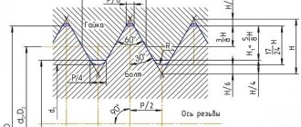
Designation of slope on drawings . The designation of slopes in the drawing is carried out in accordance with GOST 2.307-68. The amount of slope is indicated on the drawing using a leader line. The sign and magnitude of the slope are indicated on the leader line shelf. The slope sign must correspond to the slope of the line being determined, that is, one of the straight lines of the slope sign must be horizontal, and the other must be inclined in the same direction as the slope line being determined. The slope of the sign line is approximately 30°.
Dimensions, mm
Inner cones
For cones with foot
For cones with threaded hole
| Cone | Metric | Morse | Metric | |||||||||||
| Cone designation | 4 | 6 | 0 | 1 | 2 | 3 | 4 | 5 | 6 | 80 | 100 | 120 | 160 | 200 |
| Taper | 1 : 20 = 0,05 | 1 : 19,212 = 0,05205 | 1 : 20,047 = 0,04988 | 1 : 20,020 = 0,04995 | 1 : 19,922 = 0,05 | 1 : 19,254 = 0,05194 | 1 : 19,002 = 0,05263 | 1 : 19,180 = 0,05214 | 1 : 20 = 0,05 | |||||
| D | 4 | 6 | 9,045 | 12,065 | 17,780 | 23,825 | 31,267 | 44,399 | 63,348 | 80 | 100 | 120 | 160 | 200 |
| d5 | 3 | 4,6 | 6,7 | 9,7 | 14,9 | 20,2 | 26,5 | 38,2 | 54,6 | 71,5 | 90 | 108,5 | 145,5 | 182,5 |
| d6 | — | — | — | 7 | 11,5 | 14 | 18 | 23 | 27 | 33 | 39 | 52 | ||
| l5 min | 25 | 34 | 52 | 56 | 67 | 84 | 107 | 135 | 188 | 202 | 240 | 276 | 350 | 424 |
| l6 | 21 | 29 | 49 | 52 | 62 | 78 | 98 | 125 | 177 | 186 | 220 | 254 | 321 | 388 |
| g | 2,2 | 3,2 | 3,9 | 5,2 | 6,3 | 7,9 | 11,9 | 15,9 | 19 | 26 | 32 | 38 | 50 | 62 |
| h | 8 | 12 | 15 | 19 | 22 | 27 | 32 | 38 | 47 | 52 | 60 | 70 | 90 | 110 |
1. GOST provides dimensions for external tool cones.
2. Maximum deviations of cone sizes and shape tolerances according to GOST 2848-75.
What is taper? Formula for calculating taper. Designation of taper in drawings.
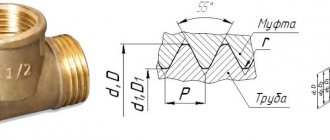
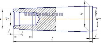
Taper . Taper is the ratio of the diameter of the base of the cone to the height. The taper is calculated using the formula K=D/h, where D is the diameter of the base of the cone, h is the height. If the cone is truncated, then the taper is calculated as the ratio of the difference between the diameters of the truncated cone and its height. In the case of a truncated cone, the conicity formula will look like: K = (Dd)/h.
Designation of taper in drawings . The shape and size of the cone is determined by drawing three of the listed dimensions: 1) the diameter of the large base D; 2) diameter of the small base d; 3) diameter in a given cross section Ds having a given axial position Ls; 4) cone length L; 5) cone angle a; 6) taper with . It is also allowed to indicate additional dimensions in the drawing as a reference.
The dimensions of standardized cones do not need to be indicated on the drawing. It is enough to indicate in the drawing the symbol of the taper according to the relevant standard.
Taper, like slope, can be indicated in degrees, as a fraction (simple, as a ratio of two numbers or as a decimal), or as a percentage. For example, a 1:5 taper can also be expressed as a 1:5 ratio, 11°25'16", with a decimal of 0.2 and a percentage of 20. For tapers used in mechanical engineering, OCT/BKC 7652 specifies a range of normal tapers. Normal tapers - 1:3; 1:5; 1:8; 1:10; 1:15; 1:20; 1:30; 1:50; 1:100; 1:200. Also 30, 45, 60, 75, 90 and 120° can be used.
When carrying out engineering and other calculations, as well as working with engineering graphics and creating drawings, it is necessary to create a slope. Taper has become very widespread and is used in the manufacture of a wide variety of parts. The taper index is calculated in most cases when creating parts that are widely used in the field of mechanical engineering. Let's consider the main parameters, features of the style and many other points in more detail.
Taper of outer and inner tapers with threaded hole
| Designation of cone size | Taper | Cone angle 2α |
| AT 7 | 1 : 19,212 = 0,05205 | 2°58’54» |
| B10; B12 | 1 : 20,047 = 0,4988 | 2°51’26» |
| B16; B18 | 1 : 20, = 0,04995 | 2°51’41» |
| B22; B24 | 1 : 19,922 = 0,05020 | 2°52’32» |
| B32 | 1 : 19,954 = 0,05194 | 2º58'31" |
| B45 | 1 : 19,002 = 0,05263 | 3°00’53» |
The cone angle 2α is calculated from the taper value with rounding 1"
Taper value
When considering taper, it should be taken into account that this indicator is directly related to the slope. This parameter determines the deviation of a straight line from a vertical or horizontal position. However, a 1:3 taper or a 1:16 taper is significantly different. The definition of slope is characterized by the following features:
- Slope refers to the ratio of the opposite side of a right triangle to the adjacent side. This parameter is also called the tangent of the angle.
- The following formula is used for calculation: i=AC/AB=tga.
It is worth considering that normal tapers are somewhat different from the previously discussed parameter. This is due to the fact that taper is the ratio of the diameter of the base to the height.
This indicator can be calculated in a variety of ways; the most widely used formula is K=D/h. In some cases, the designation is carried out as a percentage, since this variable indicator is used to determine all other parameters.
Designation of taper in the drawing
When creating technical documentation, all established standards must be taken into account, otherwise it cannot be used in the future. When considering the taper designation in the drawings, attention should be paid to the following points:
- The diameter of the large base is displayed. The figure under consideration is formed by a body of rotation, which is characterized by a diametrical indicator. In the case of a cone, there may be several of them, and the change in the indicator occurs smoothly, not stepwise. As a rule, such a figure has a larger diameter, as well as an intermediate one if there is a step.
- The diameter of the smaller base is applied. The smaller base is responsible for forming the required angle.
- The length of the cone is calculated. The distance between the smaller and larger bases is an indicator of length.
- Based on the constructed image, the angle is determined. As a rule, appropriate calculations are carried out for this. In the case of determining the size from a printed image, using a special measuring device, the accuracy is significantly reduced. The second method is used when creating a drawing for the production of non-critical parts.
The simplest designation of taper also provides for displaying additional dimensions, for example, reference. In some cases, a taper sign is used, which makes it immediately clear about the difference in diameters.
There are quite a large number of different standards that relate to the designation of taper. The features include the following:
- The angle can be specified in degrees as a fraction or as a percentage. The choice is made depending on the area of application of the drawing. An example is that in the mechanical engineering field the value of a degree is indicated.
- In the mechanical engineering field, the concept of normal taper is included in a special group. It varies within a certain range and can be 30, 45, 60, 75, 90, 120°. Similar indicators are characteristic of most products that are used in the assembly of various mechanisms. At the same time, it is much easier to maintain such values when using turning equipment. However, if necessary, inaccurate angles can be maintained, it all depends on the specific case.
- When drawing the main dimensions, a drawing font is used. It is characterized by quite a large number of features that must be taken into account. Tabular information is used for correct display.
- To begin with, the taper icon is indicated from which the arrow is drawn and the value is displayed. The display features largely depend on what kind of drawing. In some cases, a large number of different sizes are applied, making taper application much more difficult. That is why it is possible to use several different methods for displaying such information.
In the drawing, the indicator in question is indicated in the form of a triangle. This requires a digital value that can be calculated using various formulas.
Internal and external cones with a taper of 7:24 (according to GOST 15945-82)
Dimensions, mm
Example of cone 25 designation:
Cone 25 GOST 15945-82
Cone designation | D | L* (informative) |
| 10 | 15,87 | 21,8 |
| 15 | 19,05 | 26,9 |
| 25 | 25,40 | 39,8 |
| 30 | 31,75 | 49,2 |
| 35 | 38,10 | 57,2 |
| 40 | 44,45 | 65,6 |
| 45 | 57,15 | 84,8 |
| 50 | 69,85 | 103,7 |
| 55 | 88,90 | 131,6 |
| 60 | 107,95 | 163,7 |
| 65 | 133,35 | 200,0 |
| 70 | 165,10 | 247,5 |
| 75 | 203,20 | 305,8 |
| 80 | 254,00 | 390,8 |
Formula for determining taper
You can independently calculate the taper by using various formulas. It is worth considering that in most cases the indicator is indicated in degrees, but it can also be expressed as a percentage - it all depends on the specific case. The calculation algorithm is as follows:
- K=Dd/l=2tgf=2i. This formula is characterized by the fact that the taper is characterized by a double slope. It is based on obtaining the value of the major and minor diameters, as well as the distance between them. In addition, the angle is determined.
- Tgf=D/2L. In this case, the length of the segment that connects the large and small diameters, as well as the indicator of the large diameter, is required.
- F=arctgf. This formula is used to convert the indicator to degrees. Today, in most cases, degrees are used, since they are easier to maintain when directly carrying out constructions. As for percentages, they are often indicated to enable the calculation of one of the diameters. For example, if the ratio is 20% and a smaller diameter is given, then you can quickly calculate the larger one.
As previously noted, the 1:5 taper and other indicators are standardized. For this, GOST 8593-81 is used.
Calculations are not shown in the drawing. As a rule, an additional explanatory note is created for this purpose. It is quite simple to calculate the basic parameters; in some cases, a drawing is constructed, after which the angle value and other indicators are measured.
Cone angle
An important indicator when constructing various drawings is the cone angle. It is determined by the ratio of the large diameter to the smaller one. This indicator is calculated for the following reasons:
- At the time of processing, the master must take this indicator into account, since it allows him to obtain the required product with high dimensional accuracy. In most cases, processing is carried out taking into account the angle, and not the indicators of large and small diameter.
- The cone angle is calculated at the time of project development. This indicator is plotted on the drawing or displayed in a special table, which contains all the necessary information. The machine operator or foreman does not carry out calculations at the production site; all information must be indicated in the developed technological map.
- Checking the quality of a product is often carried out on a small and large basis, but tools can also be used to determine the taper index.
As previously noted, in the mechanical engineering field the indicator is standardized. In another area, the value may differ significantly from established standards. Some products are characterized by a stepped surface arrangement. In this case, it is quite difficult to carry out calculations, since there is an intermediate diameter.
Recommended dimensions of the center hole of a shortened cone
Dimensions, mm
Center holes for Morse tapers B12, B18, B24 and B45 are P-shaped according to GOST 14034-74. It is allowed to manufacture a center hole with the dimensions indicated in the table.
Morse cone notation | d2 | d3 | d4 | L |
| AT 12 | M6 | 8,0 | 8,5 | 16 |
| B18 | M10 | 12,5 | 13,2 | 24 |
| B24 | M12 | 15,0 | 17,0 | 28 |
| B32 B45 | M16 M20 | 20,0 26,0 | 22,0 30,0 | 32 40 |
What is slope?
As previously noted, slope can be considered a rather important indicator. It is represented by a line that is located at an angle to the horizon. If we consider the taper in the drawing, then it is represented by a combination of two differently directed slopes, which are combined with each other.
The concept of slope has become very widespread. In most cases, to display it, a triangle with a certain angle is constructed.
Two auxiliary sides are used to calculate the angle, which determines the inclination of the main surface.
How to determine slope
To determine the slope, it is enough to use just one formula. As previously noted, the problem can be significantly simplified by constructing a right triangle. Among the features of such work, we note the following points:
- The starting and ending points of the segment are determined. In the case of constructing a complex figure, it is determined depending on the characteristics of the drawing itself.
- A vertical line is drawn from the point above. It allows you to construct a right triangle, which is often used to show slope.
- The auxiliary line is connected to the bottom point at a right angle.
- The angle that is formed between the auxiliary and the main line at the lowest point is calculated to determine the slope.
The formula required to calculate the indicator in question was indicated above. It is worth considering that the resulting indicator is also converted into degrees.
Features of constructing slope and taper
The field of drawing has developed over a fairly long period. It has been used many centuries ago to transfer accumulated knowledge and skills. Today, the manufacture of all products can be carried out exclusively using drawings. At the same time, it receives the most attention when setting up mass production. Over a long period of development of drawing, standards have been developed that can significantly increase the readability of all information. An example is GOST 8593-81. It largely characterizes the taper and slope and the methods used to display them. Descriptive geometry is used to study modern science, as well as to create various techniques. In addition, a variety of correspondence tables have been developed that can be used when carrying out direct calculations.
Various concepts such as fillet, slope and taper are displayed in a specific way. This takes into account the scope of application of the technical documentation being developed and many other points.
The features of constructing an angle and taper include the following points:
- The main lines are displayed in a bolder style, except when there is a thread on the surface.
- When carrying out work, a variety of tools can be used. It all depends on which construction method is used in a particular case. An example is a right triangle, with the help of which a right angle or a protractor is maintained.
- The display of the main dimensions is carried out depending on the features of the drawing. Most often, a basic value is indicated, with the help of which others are determined. Today, the method of direct sizing, when it is necessary to measure lines and angles using appropriate tools taking into account the scale, is practically not used. This is due to the difficulties that arise on the production line.
In general, we can say that the basic standards are taken into account by the specialist when directly carrying out the work of constructing the drawing.
Often, to represent the slope in descriptive geometry, additional lines are created, and the angle of the slope is also indicated.
In design documentation, which often displays taper, additional information, if necessary, is displayed in a separate table.
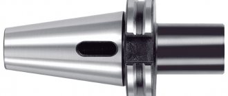
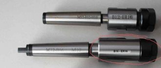
The best varieties of cones today
These days, tool Morse tapers from HSK, Capto and Kennametal are especially popular due to their quality. Good resistance to temperature changes and compliance with stringent requirements in the machine tool industry have allowed Morse tapers of these brands to become market leaders.
HSK are hollow instruments with a taper of 1:10. They are designated by a letter of the Latin alphabet and a number indicating the larger diameter of the flange. The main feature of such products is quick tool replacement, which is very important in CNC machines.
Capto tool tapers comply with the international ISO standard and are high quality products. The products are expensive due to the complexity of manufacturing, but high precision will minimize production defects when using these tools on machines. The design feature does not allow them to turn during operation of the machine; self-jamming occurs. The rigidity of the connection of Capto products is their main advantage over other competitors
Kennametal products are less common, but still do their job very well.
The products of B&S, Jacobs and Jarno are distributed mainly in the USA, as they do not have confirmation of international standards and are created, respectively, for the American market, where they are in great demand.
Bridgerport Machines has developed the R8 model for collet clamps on its equipment. But then the invention was finalized and released onto the international market. The effectiveness of this remedy caused a sensation at one time and all sorts of analogues began to appear. Today the company produces only one type of such mechanism.
The 7:24 tool taper is widely used in CNC machines, where tool change occurs automatically. Being instrumental, it has a number of advantages over conventional ones and that is why it is so popular in the machine tool industry. There are many varieties of it. Many countries have developed their own standards for it and therefore 7:24 models from different manufacturers do not replace each other.
The 1:50 cone is also widely used in the mechanical engineering industry if it is necessary to additionally fasten two products with a threaded connection. To do this, the 1:50 model has special pins that must be inserted into the workpieces, having previously drilled holes in the appropriate places.