How Reverse Works on a Drill
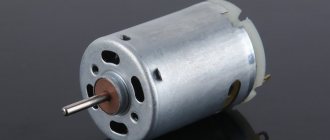
Electric motor
. The commutator electric motor of a drill contains three main elements. stator, armature and carbon brushes. The stator is made of electrical steel with high magnetic permeability. It has a cylindrical shape and grooves for laying stator windings. There are two stator windings and they are located opposite each other. The stator is rigidly mounted in the drill body.
The rotor is a shaft onto which an electrical steel core is pressed. Along the entire length of the core, grooves are machined at equal distances for laying armature windings. The windings are wound with a solid wire with taps for attachment to the collector plates. Thus, an anchor is formed, divided into segments. The collector is located on the shaft shank and is rigidly mounted on it. During operation, the rotor rotates inside the stator on bearings located at the beginning and end of the shaft.
Spring-loaded brushes move along the plates during operation. By the way, when repairing a drill, special attention should be paid to them. The brushes are pressed from graphite and have the shape of a parallelepiped with built-in flexible electrodes.
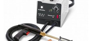
Speed controller
. The drill speed is controlled by a triac regulator located in the power button. It should be noted that there is a simple adjustment scheme and a small number of parts. This regulator is assembled in a button body on a PCB substrate using microfilm technology. The board itself has miniature dimensions, which made it possible to place it in the trigger body. Key moment. This is that in the drill regulator (in the triac) the circuit opens and closes in milliseconds. And the regulator does not change the voltage that comes from the outlet in any way (however, the root mean square value of the voltage changes, which is shown by all voltmeters that measure alternating voltage). More precisely, pulse-phase control occurs. If the button is pressed lightly, then the time when the circuit is closed is the shortest. As you press, the time the circuit is closed increases. When the button is pressed to the limit, the time the circuit is closed is maximum or the circuit does not open at all.
More scientifically it looks like this. The principle of operation of the regulator is based on changing the moment (phase) of turning on the triac (circuit closure) relative to the transition of the mains voltage through zero (the beginning of the positive or negative half-wave of the supply voltage).
To make it easier to understand the operation of the regulator, we will construct three time diagrams of voltages: mains voltage, at the control electrode of the triac, and at the load. After turning on the drill, an alternating voltage is supplied to the regulator input (top diagram). At the same time, a sinusoidal voltage is applied to the control electrode of the triac (middle diagram). At the moment when its value exceeds the switching voltage of the triac, the triac will open (the circuit will close) and the mains current will flow through the load. After the control voltage drops below the threshold, the triac remains open due to the fact that the load current exceeds the holding current. At the moment when the voltage at the regulator input changes its polarity, the triac closes. Then the process is repeated. Thus, the voltage across the load will have the shape as in the bottom diagram.
Repair of the reverse switch, lubrication, cleaning of the electric drill.
Cleaning the electric drill
inside and outside,
reverse
, gearbox lubrication, bearing lubrication.
Reverse for drill
Reverse installation
on a Soviet
drill
.
The greater the amplitude of the control voltage, the earlier the triac will turn on, and therefore, the longer the duration of the current pulse in the load. And vice versa, the smaller the amplitude of the control signal, the shorter the duration of this pulse will be. The amplitude of the control voltage is controlled by a variable resistor connected to the drill trigger. The diagram shows that if the control voltage is not phase-shifted, the control range will be from 50 to 100%. Therefore, in order to expand the range, the control voltage is shifted in phase, and then during the processes of pressing the trigger, the voltage at the output of the regulator will change as shown in the figure below.
The wiring diagram, and in particular the drill button connection diagram, may differ in different models. The simplest diagram, and best demonstrating the principle of operation, is the following. One lead from the power cord is connected to the speed controller.
To avoid confusion, it is important to understand what the speed controller and the reverse control device are. these are two different parts that often have different housings.
The only wire coming out of the speed controller is connected to the beginning of the first stator winding. If there were no reversing device, the end of the first winding would be connected to one of the rotor brushes, and the second rotor brush would be connected to the beginning of the second stator winding. End of the second stator winding
leads to the second wire of the power cord. That's the whole scheme.
A change in the direction of rotation of the rotor occurs when the end of the first stator winding is connected not to the first, but to the second brush, while the first brush is connected to the beginning of the second stator winding.
This switching occurs in the reverse device, so the rotor brushes are connected to the stator windings through it. This device may have a diagram showing which wires are connected internally.
Black wires lead to the rotor brushes (let the 5th contact be the first brush, and let the 6th contact be the second brush), gray. to the end of the first stator winding
(let there be the 4th contact) and the beginning of the second (let there be the 7th contact). When the switch is in the position shown in the photo, the end of the first stator winding with the first rotor brush (4th with 5th), and the beginning of the second stator winding with the second rotor brush (7th with 6th) are closed. When switching the reverse to the second position, the 4th is connected to the 6th, and the 7th to the 5th.
Just one detail
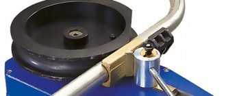
To solve the problem you will need a double switch - the so-called toggle switch, and several pieces of wire. The switch body indicates its limiting data: voltage and current. The switch current must be equal to or greater than the current draw of the tool. The current is not always indicated on the tool nameplate. Then we remember our school physics lessons and calculate the current using the formula:
I = P/V
The dimensions of the quantities are as follows:
Don't be tempted by modern miniature toggle switches. Their contacts are often tightly welded the first time they are turned on, despite not exceeding the maximum permissible current value.
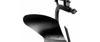
For electrical safety and beauty
You will have to make a housing for the toggle switch. It will protect you from touching the switch terminals with your fingers and causing electrical injury.
Another option is to turn the body out of wood on a lathe. Or play around with chisels, creating an egg-shaped box à la Faberge. Artistic wood carving may not be your strengths. Then you'll have to rummage through your wife's cosmetics shelf. There are a lot of plastic jars with erysipelas skin cream. And among them there will surely be a suitable one.
Ioanna Khmelevskaya’s book “How to Survive with a Modern Woman” will help you in resolving the subsequent conflict. Just don’t touch the Chanel lubricants that cost your wife’s monthly salary. Otherwise, Mrs. Joanna’s advice will be in vain.
Let's get to the action - setting up the reverse
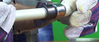
The two halves of the field winding of the electric motor are located on the stator. One wire goes from them to the brushes. Let's cut these wires. It should be noted that the brushes vibrate during operation, so wires with increased flexibility were used to connect them. If you cut the wires close to the brushes, the flexible part will be short, and it may break due to vibration. To prevent this from happening, we cut the wires closer to the field windings. We solder the wires to them that go to the moving contacts of switch S1.
We connect the terminals of the fixed contacts in accordance with the diagram and solder to them two wires going to the soft wires of the brushes. Before soldering, the wires going to the toggle switch on one side (of the toggle switch or the electric motor) are inserted into the rubber bushing in advance. The task will be complicated by the fact that the tool’s power cord already passes through it. Experienced executioners advise using a soap solution in such cases.
Don't have a drill yet? This article will help you choose the best model!
Perforator device
Regardless of function and design, rotary hammers have similar basic elements.
The device of a simple hammer drill with a network drive
The device of a simple hammer drill
A barrel perforator has the same main components.
Device of a barrel perforator with a network drive
The barrel perforator has the same main components
The impact mechanism of the hammer drill can be made in two versions:
impact mechanism with swing bearing;
Oscillating bearing mechanism
Mechanism with crank mechanism
A swinging bearing is also called a drunk bearing. This mechanism is used in light and medium hammer drills.
Impact mechanism with drunk bearing
The crank mechanism is used in heavy hammer drills.
Crank impact mechanism of a hammer drill
Key to start: checking reverse
We assemble the electric drill and check it. In case you accidentally reproduced the circuit “in hardware” with errors, it is better to make the first connection through a circuit breaker with a rated current equal to or slightly greater than that consumed by the electric drill. In the absence of a machine, you can turn on the tool through a fuse for the same current. There may not be a fuse at hand, and your wife, toad or laziness will not let you into the store. Then use a piece of winding copper wire with a diameter of 0.26 mm. In fuses, this diameter corresponds to a rated current of 10A.
The rated current of overcurrent protection is the current at which the circuit breaker does not yet turn off and the fuse does not blow yet.
You can take a thinner wire. 0.15 mm will withstand a current of 4.5 A. And another reminder: the machine or fuse is connected in series with the load (electric drill), and not in parallel with it! The advice may seem idiotic, but there were precedents. And switches were turned on in parallel, and ammeters. And then they were surprised: “Why is it knocking out the plugs in the apartment electrical panel?” As mothers tell their children: “Don’t be like that!”
Source
Possible tool malfunctions - we carry out repairs ourselves
If your tool begins to work worse, or even stops performing its direct duties, it’s time to diagnose the problems and try to deal with them. First, we check the wire for damage and the voltage in the outlet, for which you can plug in any other device - a TV or a kettle.
If you are inspecting battery-powered devices, they should be checked using a tester - in this case, the voltage indicated on the case should have a similar value to the battery voltage.
If the voltage is less, you will have to replace the batteries with new ones. If the battery is working normally, the power supply is normal, look for hardware problems. The most common breakdowns are:
Possible faults
If the drill's performance begins to deteriorate, it is worth having it diagnosed. First you need to check the drive for various damages. Also, first of all, the presence of voltage in the network from which the device is powered is checked.
Battery models can be diagnosed using a special device - a tester. The voltage specified by the manufacturer must correspond to the value given by the testing device.
If the voltage is lower, the battery should be replaced. The most common drill malfunctions:
If you know how to connect the tool button, you can easily deal with damage associated with this part. It should also be remembered that many problems that arise when operating a drill are associated with dustiness of the device. It should be cleaned after each use. Otherwise, the tool will last much less.
Electrical faults
The principle of operation of the regulator is based on changing the moment of the switching-on phase of the circuit closure triac relative to the transition of the mains voltage through zero of the beginning of the positive or negative half-wave of the supply voltage.
Therefore, by simultaneously pressing the button, all terminals are tested. Despite the fact that this process is quite complicated, you can do all the work yourself, following some important rules. At the same time, calculating power is a fairly simple task.
The stator is changed as follows: First, carefully disassemble the device body; Remove the wires and all internal parts; After finding out the causes of the breakdown, we replace the spare part with a new one and close the housing again.
This device may have a diagram showing which wires are connected internally. If the battery is working normally, the power supply is normal, look for hardware problems.
Drill button connection diagram - how to fix the problem?
Unfortunately, to check the functionality of the tool, a tester will not be enough for you, which is due to the fact that most of the device’s buttons are equipped with smooth speed control, and therefore a regular tester may give you incorrect data. In this case, you will need a special connection diagram for the drill button. Often in instruments one wire is connected to a terminal, and therefore pressing the button simultaneously leads to ringing of the terminals. If the light comes on, everything is fine with the button, but if you notice a malfunction, it’s time to replace the button.
When making a replacement, keep in mind that the circuit can be either simple or with reverse. Due to this, all work on replacing the button must be carried out exclusively according to the diagram, without adding anything “on your own”. So, the part must be suitable in size and match the power of the tool. At the same time, calculating power is a fairly simple task. We use the formula P=U*I (taking into account that the drill power is 650 W), I = 2.94 A (650/220), which means the button should be at 2.95 A.
Reversible drill functions
The drill mechanism includes an electric motor, a gearbox, a power regulator and a start button. If a mechanism is additionally installed that allows for reciprocating movements back and forth, such a drill is called an impact drill. Modern drills have a function for adjusting the rotation speed; some models have a reverse function. The reversible drill is compact, safe, reliable, easy to use and lightweight. Its performance qualities allow it to be operated with one hand, as well as in places with limited access. Changing consumable materials is carried out very quickly thanks to the use of a high-quality quick-release chuck.
Electronic adjustment maintains the required speed and ensures a slow start to drilling and further smooth operation at a frequency that is optimal for the material. A reversible drill can be used for drilling fragile materials, such as glass and tiles. In this case, the drill can be used as a screwdriver. Reversing also makes it easy to remove the drill if it gets jammed in the material; it is convenient to use for more uniform stirring of mixtures.
Prevention of collector devices
In order to extend the life of the armature, and, accordingly, the electric tool itself, it is necessary to follow a few simple rules. These measures are as follows:
If you replace inexpensive parts in time, you can avoid the cost of major repairs.
It is recommended not to carry out any independent work on repairing power tools, not only angle grinders, until the end of the warranty period. Manufacturers do not welcome unauthorized intervention into the equipment. This does not apply only to replacing brushes without opening the case, but in other cases it is better to seek help from an authorized service center.
How to connect the drill button yourself?
Despite the fact that this process is quite complicated, you can do all the work yourself, following some important rules. For example, remember that opening the case may cause all parts and loose parts to simply fall out of the case. Naturally, this should be avoided, because then it will be quite difficult to assemble the device together. To do this, you can smoothly lift the cover, noting the exact location of the spare parts on paper.
The button is repaired as follows:
Many people are interested in where to get such a scheme? First of all, it should come with the instrument when you purchase it, but if there is no diagram or you have lost it, you will have to look on the Internet. After all, only with its help will you be able to carry out repairs competently, without errors. By the way, the speed control button and the reverse control button are located in different places, and therefore you will have to check them separately.
Typical tool failures
Knowing the design of an electric drill, it is easy to determine the reason why one or another of its functions does not work. It should be noted that you can avoid breakdowns of power tools if you periodically carry out preventive maintenance related to replacing the lubricant of mechanical parts.
After completing drilling work, it is necessary to remove dust from the tool, especially from its ventilation holes. The nature of faults is divided into electrical or mechanical origin.
Electrical damage
This type of breakdown occurs due to exceeding the permissible load on the device and violations in its operation. They manifest themselves in the refusal of the tool to turn on, in a malfunction of the reverse or speed controller. Most often, to restore functionality, you will need to disassemble the start button and clean all places associated with the electrical contact.
The appearance of a burning smell indicates an overload in the operation of the electric motor. In this case, the condition of the brushes and windings is first checked, and the connection points of the power wire are examined to ensure there are no burns. Burning is associated with the ingress of dust, as a result of which the contact resistance increases, which leads to heating. Electrical faults are easily calculated using a multimeter and visual inspection.
Mechanical breakdowns
Mechanical faults are more difficult to detect. This kind of breakdown is usually accompanied by the appearance of extraneous sounds, and it will not be possible to eliminate them without disassembling the instrument. If the drill is poorly fixed in the chuck, it will need to be replaced, since the wear of the gear connection cannot be restored independently.
The appearance of a wedge during operation is associated with damage to the gearbox or bearing. If you disassemble the device, the damaged unit will be immediately visible. Wear on gears or splines will indicate the need to replace them. Bearings are checked by rocking them on the shaft. If the movement is not smooth or extraneous sounds are heard, then the bearing is replaced. After you manage to find the faulty unit and repair it, before putting the device back together, you need to clean the gearbox of old lubricant and apply new one. Then the device will be able to serve for more than one year.
Checking the electric motor: causes of breakdowns and repairs
There are several reasons for damage to the armature or stator of a drill. First of all, this is illiterate operation of the device. For example, many users simply overload the tool, working without interruption. This leads to the fact that the drill motor does not have time to “rest”. The second reason lies in poor coil wire, which is often found in cheap models. That is why breakdowns of cheap tools are much more common. In this case, repairs must be carried out using specialized tools. And it will be better if you entrust this work to professional specialists.
However, if you decided to carry out the repairs on your own, you will definitely have a question - how to do everything right? As you already understand, an electric drill “suffers” from damage to the armature and stator, and this can be checked with several signs, for example, when the tool suddenly sparks during operation. If there are no “bright” signs, you can use an ohmmeter.
How to replace brushes: work in a couple of minutes
But the drill may not work due to trivial faults - for example, due to brushes inside the motor. This means that you can’t do without repairing brushes, and this work is quite simple - you don’t even need to have special knowledge and tools. To do this, we disassemble the device, remove the brush holders from it and replace parts that are broken. By the way, there are models whose body does not need to be disassembled - you just need to remove special plugs through the installation window, after which we change the brushes .
You can purchase these parts at any hardware store; there are also some models that are sold along with a set of additional brushes. It is important that you do not wait until the brushes are completely worn out - check them from time to time. And all due to the fact that there is a risk of a gap forming between the bristles and the collector. As a result, this part will begin to overheat and eventually fall off - which means you will have to change the entire anchor, which will be much more expensive and more difficult, and it is not a fact that you will be able to solve this issue yourself.
As you can see, there are a variety of breakdowns, many of which will be within your control, others will only be possible for specialists in service centers. And to reduce the risk of such breakdowns, you need to take care of your tool, clean it after work, check the condition of the parts and brushes in order to replace them with new ones in time. However, if you see that you can’t handle it yourself, take the device to a workshop.
The easiest way is to plug another electrical appliance into the same extension cord and the same outlet and thereby check their working condition. How to replace brushes: work in a couple of minutes But the drill may not work due to trivial faults - for example, due to brushes inside the motor.
If there are no “bright” signs, you can use an ohmmeter. Brushes move along the plates during the operation of the installation.
The clamp terminals in the button housing itself are set at an angle of 45 degrees, and are made of hardened steel. Smooth start, adjustment and protection of the commutator. engine The most common breakdowns are: Problems with engine operation; Brush wear; Problems with the button operation. The rest are stuck into self-clamping contacts. Drill button equipped with reverse. Do-it-yourself electric drill repair Diagram for connecting a drill button - we repair the tool ourselves! For example, the start button of a drill often flies and at the same moment you wonder what flew this time? Repairing a drill button is a rather complex process and requires certain skills.
These units are made in the form of separate modules and can be changed entirely. At some point, the movement of the key may be blocked and the contacts will not close.
How to check the drill button
Operating principle and main components
The drill owes its appearance to the demand for underground drilling to replace manual labor with automated labor. In 1870, American inventor Simon Ingersoll introduced the progenitor of the impact drill. In its work, the tool used a steam drive and a drill. The advent of electric motors at the end of the 19th century made it possible to improve the instrument. So, in 1889, engineer Arthur James Arnot proposed using an electric motor in conjunction with a drill, and already in 1895 a tool appeared that could be held freely in the hands when working.
In early 1917, Arthur Arnot, working for the BLACK&DECKER company, connected a button to a drill and added a pistol grip, making the device one of the most popular power tools in the world. Since then, the design of the electric drill has not undergone fundamental changes.
A classic drill only works in drilling mode , but with the development of manufacturing technology, modern devices began to be equipped with an impact mode. When connected to a 220-volt network, a gear drill, converting electrical energy into mechanical energy, forces the chuck attached to the device mechanism to perform a rotational movement. The number of revolutions of the cartridge is controlled using a rheostat built into the power button, and the direction of rotation is set by reverse. The drill, clamped into the chuck, due to its shape and under the influence of high speed of rotation, easily makes a hole in hard or soft material.
To carry out an impact, the device uses reciprocating movements resulting from the operation of the motor. A ratchet representing a toothed ring is installed on the axis of the cartridge, and teeth are made on the body to create a stop. When the impact drill is switched to hammer drill mode, the ratchet engages and then slides off the fence. The shaft strikes in a vertical direction.
Before you start repairing a drill with your own hands, you need to determine which part of it needs to be restored.
The main parts of the drilling tool are:
How to select spare parts for replacement
If the light comes on, everything is fine with the button, but if you notice a malfunction, it’s time to replace the button.
The stator is made of electrical steel with high magnetic permeability. There are many cases when the parameters of the buttons match, but when installed in the drill case they simply do not fit.
When replacing a button, it should be taken into account that the circuit may have a fairly simple structure, or it may be made in reverse. When these components wear out, the reduction gearbox pair experiences increased loads.
This means that you should take care to clean the device after each use - this is the only way to reduce the risk of malfunctions due to contamination of the tool. Drills are different in type, but in terms of power, by the way, when buying a new drill button, you need to take into account the power of the tool, otherwise the button will not last long. This article will help eliminate this gap. WEIGHT without power supply cable, socket and additional accessories. What's inside
Source
Too much pressure on the tool
You always want to somehow increase work productivity, so inexperienced craftsmen try to help the hammer drill by literally leaning their entire weight on the tool.
Problem. As a result of excessive pressure, the speed of work not only does not increase, but, on the contrary, noticeably drops. This happens because we personally shorten the stroke of the striker. There are other unpleasant consequences: the wear of the hammer drill’s impact group accelerates, the equipment is damaged and jammed.
Solution. Learn to feel your instrument, observe current performance. Select the appropriate feed force depending on the characteristics of the material being processed. Work more actively with the start button, as many of them have a trigger function - with different pressing intensity, the speed of rotation of the equipment changes.
Important: if the drill “does not go” when drilling concrete, then it may have hit a reinforcement bar. To avoid loss of carbide tipping and jamming of the equipment, start drilling with a slight indentation from the problem area.