Morse cones
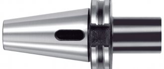
The Morse taper, proposed by inventor Stephen Morse, is the most commonly used tool mounting method. The existing division into eight sizes, from KM0 to KM7, and nine shortened sizes allows the use of a tapered shank for various cutting tools, equipment and accessories. The taper in this case varies in the ratio from 1:19.002 (at an angle of 1°25′43″) to 1:20.047 (the angle at this ratio is 1°30′26″). KM7 is not recommended for use by domestic GOST 25557-82 and instead a metric cone No. 80 is used, for example, in the spindle hole of some lathes. The standard size of the cone used as a tool shank depends on the installation method and purpose of the latter, and can be either shortened, threaded, or with a claw.
Preface
Preface
The goals, basic principles and basic procedure for carrying out work on interstate standardization are established in GOST 1.0-2015 “Interstate standardization system. Basic provisions" and GOST 1.2-2015 "Interstate standardization system. Interstate standards, rules and recommendations for interstate standardization. Rules for the development, adoption, updating and oVNIIINSTRUMENT" (JSC "VNIIINSTRUMENT") based on its own translation into Russian of the English version of the standard specified in paragraph 5
2 INTRODUCED by the Interstate Technical Committee for Standardization MTK 95 “Tool”
3 ADOPTED by the Interstate Council for Standardization, Metrology and Certification (Minutes dated November 22, 2021 N 93-P) The following voted for adoption:
| Short name of the country according to MK (ISO 3166) 004-97 | Country code according to MK (ISO 3166) 004-97 | Abbreviated name of the national standardization body |
| Azerbaijan | AZ | Azstandard |
| Armenia | A.M. | Ministry of Economy of the Republic of Armenia |
| Belarus | BY | State Standard of the Republic of Belarus |
| Georgia | G.E. | Gruzstandart |
| Kazakhstan | KZ | Gosstandart of the Republic of Kazakhstan |
| Kyrgyzstan | KG | Kyrgyzstandard |
| Moldova | M.D. | Moldova-Standard |
| Russia | RU | Rosstandart |
| Tajikistan | T.J. | Tajikstandard |
| Turkmenistan | TM | Main State Service "Turkmenstandartlary" |
| Uzbekistan | UZ | Uzstandard |
| Ukraine | U.A. | Ministry of Economic Development of Ukraine |
4 By Order of the Federal Agency for Technical Regulation and Metrology dated March 20, 2021 N 160-st, the interstate standard GOST 25557-2016 (ISO 296:1991) was put into effect as a national standard of the Russian Federation on January 1, 2018.
5 This standard is modified from the international standard ISO 296:1991* “Machines. Self-holding tapers for tool shanks” (“Machine tools – Self-holding tapers for tool shanks”, MOD). ________________ * Access to international and foreign documents mentioned in the text can be obtained by contacting User Support
. — Note from the database manufacturer. At the same time, the needs of the national economies of the countries indicated above and the features of interstate standardization are taken into account in additional sections, paragraphs that are highlighted by enclosing frames of thin lines, and information explaining the reasons for the inclusion of these provisions is given in the additional Appendix YES. The international standard was developed by the Technical Committee for Standardization ISO/TC 39 “Machines” of the International Organization for Standardization (ISO). The name of this standard has been changed relative to the name of the specified international standard to bring it into compliance with GOST 1.5 (subsection 3.6). A comparison of the structure of this standard with the structure of the international standard used in it is given in the additional appendix DB. Information on the compliance of reference interstate standards with international standards used as reference in the applied international standard is given in Additional Appendix DV
6 INSTEAD GOST 25557-2006 (ISO 296:1991) Information on changes to this standard is published in the annual (as of January 1 of the current year) information index “National Standards”, and the text of changes and amendments is published in the monthly information index “National Standards” " In case of revision (replacement) or cancellation of this standard, the corresponding notice will be published in the monthly information index “National Standards”. Relevant information, notices and texts are also posted in the public information system - on the official website of the Federal Agency for Technical Regulation and Metrology on the Internet (www.gost.ru)
Morse and metric tapers with threaded hole
For reliable fixation of tools, such as cutters, a Morse taper with an internal threaded hole is used. Fixing (tightening) is performed using a pin, or a bolt if the tool is installed in the adapter sleeve. This design also allows for quick and convenient tool changes by squeezing out the tapered shank.
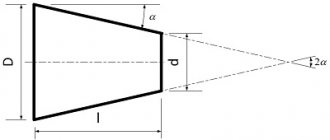
Basic dimensions of external tool metric and Morse tapers with threaded hole
| Cone name | N cone | Taper | D, mm | D 1 , mm | d, mm | l, mm | Lmax , mm | tmax , mm | M | t 1, min , mm |
| Morse | 1 | 1:20,047 | 12,065 | 12,2 | 9 | 3,5 | 57 | 5 | M6 | 16 |
| 2 | 1:20,020 | 17,780 | 18 | 14 | 5 | 69 | M10 | 24 | ||
| 3 | 1:19,992 | 23,825 | 24,1 | 19 | 86 | 7 | M12 | 28 | ||
| 4 | 1:19,254 | 31,267 | 31,6 | 25 | 6,5 | 109 | 9 | M16 | 32 | |
| 5 | 1:19,002 | 44,399 | 44,7 | 35,7 | 136 | 10 | M20 | 40 | ||
| 6 | 1:19,180 | 63,348 | 63,8 | 51 | 8 | 190 | 16 | M24 | 50 | |
| Metric | 80 | 1:20 | 80 | 80,4 | 67 | 8 | 204 | 24 | M30 | 65 |
| 100 | 100 | 100,5 | 85 | 10 | 242 | 30 | M36 | 80 | ||
| 120 | 120 | 120,6 | 102 | 12 | 280 | 36 | ||||
| 160 | 160 | 160,8 | 138 | 16 | 356 | 48 | M48 | 100 | ||
| 200 | 200 | 201 | 174 | 20 | 432 | 60 | ||||
Morse and metric tapers with claw
The design of spindles for drilling, drilling and milling, and some types of other machines has a groove for a cone foot to securely fix the cutting tool and prevent rotation. The through transverse hole is designed for installation in the wedge groove, and easy removal of the conical tool mandrel.
Basic dimensions of external instrumental metric and Morse tapers
| Cone name | N cone | Taper | D, mm | D 1 , mm | d 1 , mm | a, mm | Lmax , mm | lmax , mm | emax , mm |
| Metric | 4 | 1:20 | 4 | 4,1 | — | 2 | — | ||
| 6 | 6 | 6,2 | 3 | ||||||
| Morse | 0 | 1:19,212 | 9,045 | 9,2 | 6,1 | 3 | 59,5 | 56,5 | 10,5 |
| 1 | 1:20,047 | 12,065 | 12,2 | 9 | 3,5 | 65,5 | 62 | 13,5 | |
| 2 | 1:20,020 | 17,780 | 18 | 14 | 5 | 80 | 75 | 16 | |
| 3 | 1:19,992 | 23,825 | 24,1 | 19,1 | 99 | 94 | 20 | ||
| 4 | 1:19,254 | 31,267 | 31,6 | 24,5 | 6,5 | 124 | 117,5 | 24 | |
| 5 | 1:19,002 | 44,399 | 44,7 | 35,7 | 156 | 149,5 | 29 | ||
| 6 | 1:19,180 | 63,348 | 63,8 | 51 | 8 | 218 | 210 | 40 | |
| Metric | 80 | 1:20 | 80 | 80,4 | 69 | 8 | 228 | 220 | 48 |
| 100 | 100 | 100,5 | 87 | 10 | 270 | 260 | 58 | ||
| 120 | 120 | 120,6 | 105 | 12 | 312 | 300 | 68 | ||
| 160 | 160 | 160,8 | 141 | 16 | 396 | 380 | 88 | ||
| 200 | 200 | 201 | 177 | 20 | 480 | 460 | 108 | ||
Diameters D1 and d1 are theoretically calculated and depend on the nominal dimensions D, a and l.
Basic dimensions of internal instrumental metric and Morse tapers
| Cone name | N cone | Taper | D, mm | g, mm | h, mm | l 1 , mm |
| Metric | 4 | 1:20 | 4 | 2,2 | 8 | 21 |
| 6 | 6 | 3,2 | 12 | 29 | ||
| Morse | 0 | 1:19,212 | 9,045 | 3,9 | 15 | 49 |
| 1 | 1:20,047 | 12,065 | 5,2 | 19 | 52 | |
| 2 | 1:20,020 | 17,780 | 6,3 | 22 | 62 | |
| 3 | 1:19,992 | 23,825 | 7,9 | 27 | 78 | |
| 4 | 1:19,254 | 31,267 | 11,9 | 32 | 98 | |
| 5 | 1:19,002 | 44,399 | 15,9 | 38 | 125 | |
| 6 | 1:19,180 | 63,348 | 19 | 47 | 177 | |
| Metric | 80 | 1:20 | 80 | 26 | 52 | 186 |
| 100 | 100 | 32 | 60 | 220 | ||
| 120 | 120 | 38 | 70 | 254 | ||
| 160 | 160 | 50 | 90 | 321 | ||
| 200 | 200 | 62 | 110 | 388 | ||
Boring bar, Morse No. 2 (set);
Boring bar, dia. 38 mm with Morse shank No. 2 - for cutters dia. 8 mm, GARVIN
Boring bar, Morse No. 3, dia. 27 mm for installing a cutter with a cross section of 6.3 mm “flying”
0 out of 5
(No reviews yet.)
0.00 rub.
Availability: Out of stock Article: 20-034-S01 Category: Boring bars
FacebookTwitterLinkedInGoogle PlusEmail
- Details
- Reviews (0)
Shortened Morse tapers
Due to the excess length of the Morse cone in some of its applications, a standard of shortened cones was formed.
The cone designation contains the value of the largest diameter formed after decreasing the length while maintaining the ratio. Thus, nine standard sizes of shortened cones, B7, B10, B12, B16, B18, B22, B24, B32, B45, have become widespread when installing drill chucks and other tools. The values of diameters D1 and d1 are theoretical and calculated and depend on the nominal dimensions D and L.
Main dimensions of shortened Morse tapers
| Cone name | N Morse taper | D, mm | D 1 , mm | d 1 , mm | amax , mm | L, mm | M | l 1 , mm |
| B7 | 0 | 7,067 | 7,2 | 6,5 | 3,0 | 11,0 | — | |
| B10 | 1 | 10,094 | 10,3 | 9,4 | 3,5 | 14,5 | — | |
| B12 | 12,065 | 12,2 | 11,1 | 18,5 | M6 | 16,0 | ||
| B16 | 2 | 15,733 | 16,0 | 14,5 | 5,0 | 24,0 | — | |
| B18 | 17,780 | 18,0 | 16,2 | 32,0 | M10 | 24,0 | ||
| B22 | 3 | 21,793 | 22,0 | 19,8 | 40,5 | — | ||
| B24 | 23,825 | 24,1 | 21,3 | 50,5 | M12 | 28,0 | ||
| B32 | 4 | 31,267 | 31,6 | 28,6 | 6,5 | 51,0 | M16 | 32,0 |
| B45 | 5 | 44,399 | 44,7 | 41,0 | 64,5 | M20 | 40,0 | |
Turning a cone on a lathe
1. Turning a conical surface while turning the cross slide
when fed manually, as shown in Figure 20a. The angle of rotation is determined by the formula:
tg = (D – d)/2l, where D and d are the diameters of the cone, mm; l – cone length, mm. This method can be used to process both external and internal conical surfaces.
2. Turning cones with a wide cutter
with transverse feed (Figure 20b). This method is used when processing conical surfaces of short length. The width of the cutter should slightly exceed the length of the surface being processed.
3. Turning cones with transverse displacement of the tailstock body
shown in Figure 20c. In this way, long parts with a slight taper ( 8 o) are processed. The amount of displacement of the tailstock from the axis
h = L(D – d)/2l, where l is the length of the part, mm.
4. Turning cones using a copying machine
(conical)
ruler
is shown in Figure 20d. Long conical parts are processed in this way. To do this, a ruler with a slider is placed on a bracket attached to the bed, which is kinematically connected to the transverse support of the machine.
Figure 20 – Methods for processing conical surfaces.
Turning of a conical surface with rotation of the transverse slide and manual feed (a)
1 – axis of rotation of the transverse caliper; 2 – manual feed handle.
Turning cones with a wide cutter (b). Turning cones with transverse displacement of the tailstock body (c). Turning cones using a copy (cone) ruler (d)
1, 5 – ruler fastening bolts; 2 – bracket; 3 – copy ruler; 4 – slider; 6 – traction; 7 – bed; 8 – part; 9 – transverse support
Kinematic diagram of a screw-cutting lathe 1k62
When analyzing the kinematic diagrams of metal-cutting machines, the main working movement
and
feed movement
.
Main labor movement
. The main movement drive – the gearbox has 6 shafts. Shaft I (Figure 21) is driven by an electric motor
(N = 10 kW, n = 1450 rpm) through a V-belt drive with pulleys with a diameter of 142 and 254 mm. This shaft houses a plate-type friction clutch M1, the switching of which reverses the rotation of the spindle. When the clutch is turned to the left, rotation from shaft I to shaft II is transmitted through gears 56 - 34 or 51 - 39, and when the clutch is turned to the right - through gears 50 - 24 and 36 - 38. In the latter case, the transmission of motion is carried out through a block of intermediate (parasitic) gears 24 - 36, which change the direction of movement of shaft II, and, consequently, the direction of rotation of the spindle.
When the clutch is turned to the left, direct rotation of the spindle is ensured - clockwise when viewed from its non-working side, when turned to the right - reverse rotation. Reversing the spindle movement is necessary for carrying out heavy cutting work (large diameters, hard materials) when the spindle rotates in reverse, as well as for removing a tool fixed in the tailstock when machining holes. In the following, only the direct working stroke will be considered.
From shaft II to shaft III, rotation is transmitted through gears 29 – 47; 21 – 55; 38 - 38. From shaft III, the movement can be directly transmitted through gears 65 - 43 to shaft VI - the spindle, thus providing the 6 highest frequencies of its rotation.
On the other hand, movement from shaft III can be transmitted to shaft IV through gears 22 - 88 or 45 - 45, and from shaft IV to shaft V through gears 22 - 88 or 45 - 45 and then 27 - 54 to the spindle. Shafts IV and V are a busting system. Thanks to this system, the spindle receives another 24 rotation speeds, for a total of 30.
In fact, the machine has 23 rotation speeds, since in some gears the speeds are duplicated.
The equation of the kinematic chain of the main movement in general looks like this:
where nshp – spindle rotation speed, rpm; ned – electric motor rotation speed, rpm; ded – diameter of the pulley on shaft I, mm; — slip coefficient of the V-belt transmission ( 0.01 0.015); i – transmission ratio from one shaft to another.
Feed movement
contains:
— step increasing link;