Peculiarities
The peculiarity of this thread is determined based on the following parameters:
- geometric parameters;
- size (number of threads per inch);
- cutting direction;
- required drill diameter;
- accuracy class;
- application area.
All types of UNF threads belong to the fine category. It can be thought of as metric 60 degrees. A distinctive feature is the unit of measurement - this is an inch. That's why it's called inch thread or American thread. Each small carving has its own distinctive dimensions. Its analogue is the English BSW thread sizes, which are located in special tables
Specific features can be identified by markings. It consists of the following elements:
- in the first place is the abbreviation UNF (literally translated means “Unified Group of Small Threads”);
- Next comes the size in inches;
- completes the marking of the step value.
All parameters and features are given in more detail in special tables indicating the purpose and rules for using fasteners in American connections.
UNC and UNF standard threads. Drill diameter for UNC, UNF thread
In foreign-made cars and household appliances, UNC and UNF threads are widely used. For example, UNC 3/8 and 1/4 inch threads can be found in devices for fixing video cameras (tripods, monopods, flash mounts). UNC, UNF is a US standard, the threads of which are used in European countries, and in particular the USA. In Russia, UNC and UNF threads are called inch threads.
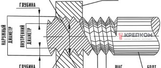
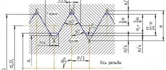
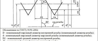
The UNC, UNF thread profile is the same as the 60° metric thread, but the thread dimensions are calculated in inches.
UNC - coarse thread; UNF - fine thread.
The table below shows detailed thread dimensions and the required drill diameter for the thread to be cut.
| UNC Unified Coarse Thread | |||||
| Thread designation | Outer diameter, inch | Outer diameter, mm | Diameter of drill bit for thread, mm | Threads per inch | Cut thread pitch, mm |
| N 1 - 64 UNC | 0,073 | 1,854 | 1,5 | 64 | 0,397 |
| N 2 - 56 UNC | 0,086 | 2,184 | 1,8 | 56 | 0,453 |
| N 3 - 48 UNC | 0,099 | 2,515 | 2,1 | 48 | 0,529 |
| N 4 - 40 UNC | 0,112 | 2,845 | 2,35 | 40 | 0,635 |
| N 5 - 40 UNC | 0,125 | 3,175 | 2,65 | 40 | 0,635 |
| N 6 - 32 UNC | 0,138 | 3,505 | 2,85 | 32 | 0,794 |
| N 8 - 32 UNC | 0,164 | 4,166 | 3,5 | 32 | 0,794 |
| N 10 - 24 UNC | 0,19 | 4,826 | 4 | 24 | 1,058 |
| N 12 - 24 UNC | 0,216 | 5,486 | 4,65 | 24 | 1,058 |
| 1/4″ - 20 UNC | 0,25 | 6,35 | 5,35 | 20 | 1,27 |
| 5/16″ - 18 UNC | 0,313 | 7,938 | 6,8 | 18 | 1,411 |
| 3/8″ - 16 UNC | 0,375 | 9,525 | 8,25 | 16 | 1,587 |
| 7/16″ - 14 UNC | 0,438 | 11,112 | 9,65 | 14 | 1,814 |
| 1/2″ - 13 UNC | 0,5 | 12,7 | 11,15 | 13 | 1,954 |
| 9/16″ - 12 UNC | 0,563 | 14,288 | 12,6 | 12 | 2,117 |
| 5/8″ - 11 UNC | 0,625 | 15,875 | 14,05 | 11 | 2,309 |
| 3/4″ - 10 UNC | 0,75 | 19,05 | 17 | 10 | 2,54 |
| 7/8″ - 9 UNC | 0,875 | 22,225 | 20 | 9 | 2,822 |
| 1″ - 8 UNC | 1 | 25,4 | 22,25 | 8 | 3,175 |
| 1 1/8″ - 7 UNC | 1,125 | 28,575 | 25,65 | 7 | 3,628 |
| 1 1/4″ - 7 UNC | 1,25 | 31,75 | 28,85 | 7 | 3,628 |
| 1 3/8″ - 6 UNC | 1,375 | 34,925 | 31,55 | 6 | 4,233 |
| 1 1/2″ - 6 UNC | 1,5 | 38,1 | 34,7 | 6 | 4,233 |
| 1 3/4″ - 5 UNC | 1,75 | 44,45 | 40,4 | 5 | 5,08 |
| 2″ - 4 1/2 UNC | 2 | 50,8 | 46,3 | 4,5 | 5,644 |
| 2 1/4″ - 4 1/2 UNC | 2,25 | 57,15 | 52,65 | 4,5 | 5,644 |
| 2 1/2″ - 4 UNC | 2,5 | 63,5 | 58,5 | 4 | 6,35 |
| 2 3/4″ - 4 UNC | 2,75 | 69,85 | 64,75 | 4 | 6,35 |
| 3″ - 4 UNC | 3 | 76,2 | 71,1 | 4 | 6,35 |
| 3 1/4″ - 4 UNC | 3,25 | 82,55 | 77,45 | 4 | 6,35 |
| 3 1/2″ - 4 UNC | 3,5 | 88,9 | 83,8 | 4 | 6,35 |
| 3 3/4″ - 4 UNC | 3,75 | 95,25 | 90,15 | 4 | 6,35 |
| 4″ - 4 UNC | 4 | 101,6 | 96,5 | 4 | 6,35 |
| UNC Unified Coarse Thread | |||||
| Thread designation | Outer diameter, inch | Outer diameter, mm | Diameter of drill bit for thread, mm | Threads per inch | Cut thread pitch, mm |
| N 0 - 80 UNF | 0,06 | 1,524 | 1,25 | 80 | 0,317 |
| N 1 - 72 UNF | 0,073 | 1,854 | 1,55 | 72 | 0,353 |
| N 2 - 64 UNF | 0,068 | 2,184 | 1,9 | 64 | 0,397 |
| N 3 - 56 UNF | 0,099 | 2,515 | 2,15 | 56 | 0,453 |
| N 4 - 48 UNF | 0,112 | 2,845 | 2,4 | 48 | 0,529 |
| N 5 - 44 UNF | 0,125 | 3,175 | 2,7 | 44 | 0,577 |
| N 6 - 40 UNF | 0,138 | 3,505 | 2,95 | 40 | 0,635 |
| N 8 - 36 UNF | 0,164 | 4,166 | 3,5 | 36 | 0,705 |
| N 10 - 32 UNF | 0,19 | 4,826 | 4,1 | 32 | 0,794 |
| N 12 - 28 UNF | 0,216 | 5,486 | 4,7 | 28 | 0,907 |
| 1/4″ - 28 UNF | 0,25 | 6,35 | 5,5 | 28 | 0,907 |
| 5/16″ – 24 UNF | 0,313 | 7,938 | 6,9 | 24 | 1,058 |
| 3/8″ – 24 UNF | 0,375 | 9,525 | 8,5 | 24 | 1,058 |
| 7/16″ – 20 UNF | 0,438 | 11,112 | 9,9 | 20 | 1,27 |
| 1/2″ – 20 UNF | 0,5 | 12,7 | 11,5 | 20 | 1,27 |
| 9/16″ - 18 UNF | 0,563 | 14,288 | 12,9 | 18 | 1,411 |
| 5/8″ – 18 UNF | 0,625 | 15,875 | 14,5 | 18 | 1,411 |
| 3/4″ - 16 UNF | 0,75 | 19,05 | 17,5 | 16 | 1,587 |
| 7/8″ - 14 UNF | 0,875 | 22,225 | 20,4 | 14 | 1,814 |
| 1″ – 12 UNF | 1 | 25,4 | 23,25 | 12 | 2,117 |
| 1 1/8″ - 12UNF | 1,125 | 28,575 | 26,5 | 12 | 2,117 |
| 1 1/4″ - 12 UNF | 1,25 | 31,75 | 29,5 | 12 | 2,117 |
| 1 3/8″ - 12 UNF | 1,375 | 34,925 | 32,75 | 12 | 2,117 |
| 1 1/2″ - 12 UNF | 1,5 | 38,1 | 36 | 12 | 2,117 |
Application of UNF thread
Cylindrical inch threads, which include UNF and BSW, have a fine pitch. Therefore, they are used for various fastening structures that are subject to increased connection requirements. This fine pitch thread is used in two types of connections:
- high strength;
- regulatory.
Possessing an inch thread measuring one quarter and one and a half inches (according to the American standard), it is used in the following units and structures:
- various types of pipe connections (inch, calibrated, plumbing, gas);
- hydraulic structures (fittings, adapter taps);
- thread adapters;
- union nuts;
- bolts and nuts for fastening structures of various units.
Its versatility and good reliability make it possible to use the American design in mechanical engineering and in the production of machine tools, equipment and tools.
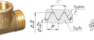
Tapered pipe threads
drawing of pipe tapered threads
Tapered pipe thread GOST 6211-81 (1st standard size)
Parameter Unit: Inch
Fits a rounded 55° straight pipe thread profile. See the top part (I) of the 3D image "drawing of pipe tapered threads".
Symbol
International: R
Japan: PT
UK: BSPT
The letter R and the nominal diameter Dy are indicated. The designation R means external thread, Rc internal, Rp internal cylindrical. By analogy with cylindrical pipe threads, LH is used for left-hand threads.
Examples:
R1 ½ - external pipe thread, nominal diameter Dy = 1 ½ inches.
R1 ½ LH - external pipe thread conical, nominal diameter Dy = 1 ½ inches, left.
Conical inch thread GOST 6111 - 52 (2nd standard size)
Parameter Unit: Inch
Produced on surfaces with a taper of 1:16
Has a profile angle of 60°. See the bottom part (II) of the 3D image "drawing of pipe tapered threads". It is used in pipelines (fuel, water, air) of machines and machines with relatively low pressure. The use of this type of connection assumes tightness and locking of the thread without additional special means (linen threads, yarn with red lead).
Symbol
The first letter is K, then GOST.
Example:K ½ GOST 6111 - 52
It stands for: inch conical thread with an outer and inner diameter in the main plane approximately equal to the outer and inner Ø of a cylindrical pipe thread G ½
Table of main parameters of tapered inch threads
| Thread size designation (d, inches) | Number of threads per 1″ n | Thread pitch S, mm | Thread length, mm | Outer thread diameter in the main plane d, mm | |
| Working l1 | From the end of the pipe to the main plane l2 | ||||
| 1/16 | 27 | 0,941 | 6,5 | 4,064 | 7,895 |
| 1/8 | 27 | 0,941 | 7,0 | 4,572 | 10,272 |
| 1/4 | 18 | 1,411 | 9,5 | 5,080 | 13,572 |
| 3/8 | 18 | 1,411 | 10,5 | 6,096 | 17,055 |
| 1/2 | 14 | 1,814 | 13,5 | 8,128 | 21 793 |
| 3/4 | 14 | 1,814 | 14,0 | 8,611 | 26,568 |
| 1 | 11 1/2 | 2,209 | 17,5 | 10,160 | 33,228 |
| 1 1/4 | 11 1/2 | 2,209 | 18,0 | 10,668 | 41,985 |
| 1 1/2 | 11 1/2 | 2,209 | 18,5 | 10,668 | 48,054 |
| 2 | 11 1/2 | 2,209 | 19,0 | 11,074 | 60,092 |
Making threads
The procedure and rules for cutting it according to the American UNF standard do not differ from the cutting method using the metric system. The only difference is the use of special tools and methods for setting up the machine. As for metric connections, manual or mechanical thread cutting is used. Both methods are applicable for cutting internal and external threads.
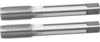
In the manual method, special sets of taps and dies are used, which are designed for cutting. Such sets include devices of a standard size and comply with accepted international standards.
The basic rules that must be followed when cutting are:
- selection of the required drill diameter;
- preliminary selection of diameter (it must be equal to the diameter minus the pitch).
These data are provided in reference tables. If such tables are missing, the calculation must be done independently.
At enterprises engaged in the mass production of parts that use inch American cylindrical threads of this standard, mechanical cutting methods are used. This operation is performed using the following equipment:
- lathes equipped with special taps;
- threading machines capable of producing external and internal cutting;
- screw-cutting lathes equipped with numerical control.
The third type of machines is equipped with special programs that allow you to cut the entire list of UNF.
Cutting technology
UNC threads are created by removing a portion of material from the surfaces of cylindrical and tapered workpieces. This is done on machines. Depending on the type, taps and dies are used (for internal and external, respectively).
The shank is used for installation in the driver or chuck of the machine. The working part is divided into intake and calibrating. The first carries out cutting, the second serves for calibration. The cutting edges are formed by longitudinal grooves, which also provide chip exit. The cutting parts limited by grooves are called cutting feathers.
On machine tools, machine options are most often used, however, for hard and viscous materials, specific sets of taps are required, including two or three tools. They differ in the purity of processing and perform different amounts of work. So, for a set of two taps the proportion is 75/25%, for a set of three – 60/30/10%. Structurally, the taps of one set differ in the length of the intake part, which is the longest in the draft version. For workpieces with a surface interrupted by a groove or groove, tools with a number of grooves not a multiple of the number of grooves and with helical grooves are used. The latter are also suitable for holes with a length of two diameters or more. In this case, the direction of the screw groove must correspond to the thread being cut. Specific options are represented by grooveless taps. They are designed to create short through threads. Such tools are more durable and have better quality of work. Another specific version of taps is with staggered teeth, designed for short through threads on tough materials. They reduce friction, improve coolant flow and chip formation. Taps are installed similarly to dies or in cartridges for them. The speed of work is 5-12 for steel and 6-22 m/s for other materials. When cutting, cooling with oil or emulsion is required.
Due to the different configurations on the machines, they are mounted in different holders. Thus, for lerks, lerk holders are used, represented by cranks in the form of frames with 2 handles. The die is located inside and is fixed with three screws that go into the recesses on its sides. The frames for sliding options are made in the form of oblique frames with 2 handles. Half dies are placed in the hole, adjusting the size with a pressure screw.
Before cutting the thread, the surface of the workpiece is treated. For an external connection, it is necessary to ensure a smaller diameter in relation to the outer diameter of the thread. This difference is approximately 0.1-0.3 mm depending on the size of the connection. At the end, a chamfer corresponding to the height of the profile is removed to form an approach. The die is mounted with a holder in the socket of the head or tailstock quill. The speed of work is determined by the type of material. So, for steel blanks it is 3-4, for cast iron - 2-3, for brass - 10-15 m/min.