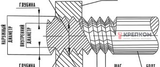
Measuring with a thread gauge
Accurately identifying the threads on a fastener is critical before selecting and installing the correct fittings.
How to measure thread:
- Use a combination caliper to measure the thread diameter. It is worth taking into account that the threads of the used fitting may wear out and become distorted, so calculations may not be accurate.
- Use a thread gauge to determine the number of threads per inch. For metric connections, the distance between the threads is calculated. To do this, you need to place the device on the thread until it fits snugly, and then compare your measurements with the thread diagram.
- If the port is located at an angle, determine the angle of inclination using a protractor on the sealing surface. The center line of the fitting and gauge should be parallel.
Using a combination of three tools, identifying connectors is easy. The use of a caliper, thread gauge and protractor allows accurate measurements of most connections.
A caliper is used to measure the diameter of an external internal thread. When comparing calibration measurements to thread diagrams, keep in mind that threads on connections that have been in service may be worn and distorted from use. This results in inaccurate comparisons with thread tables.
For English, British and other European threads, the pitch meter has an inch scale. However, for metric parts, the device will determine the distance between threads in millimeters.
The protractor is used by placing it on the sealing surface. The center line of the fitting end and gauge should be parallel. In English, the thread size system and pitch (number of threads per inch) are specified along with the thread type.
When using a thread gauge, you need to align it with the threads and make sure that it fits snugly. Match the measurement to the thread, then calculate the diameter using a caliper.
How to distinguish metric threads from inch threads
Only craftsmen who deal with threads on a daily basis are able to distinguish metric from inch threads, or vice versa, by eye. If a non-professional tries to distinguish threads by eye, there is a very high risk of mistaking a 5/16-inch UNC bolt for a metric M8. You can determine compliance with the thread type using a thread gauge, but when such an identifier is not available, you must resort to other methods.
The easiest way to understand what type of thread is on a bolt is to use a nut with already known parameters (and vice versa). If this is not possible, then you should resort to the following actions:
- Inspect the head of the part, which may have radial lines
- If radial lines are present on the head of the fastener, this indicates the presence of an inch thread.
- The absence of radial lines confirms the use of metric threads
However, this method is not always acceptable, since fasteners with strength classes from 0 to 2 are not marked. The presence of lines and numbers on the bolt head indicates the strength of the product.
Measuring thread pitch without a thread gauge
For metric fasteners, thread pitch is used instead of TPI. Distance is also measured in millimeters.
To determine the thread pitch, a caliper is used to calculate the distance from the top of one thread to the next. The formula used for this is M2 x 4 x 5 mm, where M2 refers to the diameter of the bolt (in millimeters), i.e. 4 is the thread pitch in millimeters, which means it is equal to 4 mm between each thread peak, and 5M is bolt length.
Thread pitch is used to measure the threads of a bolt or nut to ensure they fit together. If the threads of the bolt and nut are different, they either do not grip or wear out the threads, resulting in an unusable connection.
Small threaded fasteners have a denser helical structure and are usually less pronounced. A coarse threaded connection has larger and deeper threads. This means that if the threads are slightly damaged, it may still work. Most standard metric fasteners have fine and coarse threads. Each of them can be identified using or thread pitch.
In the US and UK, fasteners typically have thread sizes ranging from ¼ to 20 inches and ¼ to 28 inches. To determine which of these threads is coarse and which is fine, you simply need to take the TPI number (20 and 28) and compare them.
Don't forget that coarse thread means the thread is larger, so smaller ones will be able to fit within an inch. So 20 means it's a coarse thread and 28 means it's a fine thread. TPI and thread pitch will vary depending on the diameter of the fastener, so the value will not always be 20 and 28.
For metric fasteners, similar parameters would be represented as M8 x 1.25 or M8 x 1. For thread pitch, the distance between two points is the second number, meaning the higher the number, the fewer threads. It follows that M8 x 1.25 is a coarse thread, and M8 x 1 is a fine thread.
Types of thread gauges and their features
Due to the fact that there are two main types of threads - inch and metric, it is not difficult to guess that the tools for determining them are of two types:
- Metric - designed exclusively for working with workpieces with metric threads. The device measures the pitch and profile of cutting, the diameter of which ranges from 1 to 600 millimeters. The design of the tool contains up to 20 combs, which are steel plates with teeth. Using these plates, you can determine the cutting pitch from 0.4 to 7 mm. Such a device is called a metric thread gauge, since it is used to determine the pitch and profile of the metric thread already existing on the workpiece. The devices allow you to evaluate the correct manufacturing of fasteners such as nuts, bolts, studs, etc. Metric instruments are distinguished by their simple manufacturing design, high strength, and corresponding markings on the body in the form of “M60”. The scope of application of the tool is mechanical engineering, instrument making, etc.
- Inch - designed only for working with inch types of cuts. The device is used in the field of radio electronics, aircraft manufacturing, plumbing, as well as in the production of various machine tools. The set of inch thread gauge contains 17 plates with corresponding teeth, which differ from the metric device in angle of location. The smallest comb has 28 turns, and the largest has 4 edges. The pitch is determined by the number of threads per 1 inch. A distinctive feature of the inch tool is that there is a marking in the form “D55” on the body. In the household, inch thread gauges are used when working with plumbing fixtures
- Trapezoidal - a special device designed to work with trapezoidal types of cuts. Another name for this device is T-thread gauge
- Universal - devices that have plates for calibrating inch and metric threads. Such devices allow you to simultaneously work with different types of cuts, which is especially important in plumbing
When you know what types of thread gauges there are, it remains to understand the issue of their correct use. If you don’t know how to use a thread gauge, then we’ll look at the procedure for determining the thread pitch in detail.
This is interesting!
When measuring the pitch in a metric thread, the distance between two turns is determined. In inch threading, the distance between two peaks is not measured, as is the case with metric threads, but the number of turns is determined. This is the number of turns that are spaced 1 inch apart.
Measuring threads with a caliper
The first step is to determine whether the threads are tapering. To do this, place the points of the caliper on either side of the object that needs to be measured. Align it to the outside of the threads at the lower end, away from the head. This is how the width is determined.
Next, you need to move the tip so that it touches the threads. The measurement should appear on the screen if the instrument has a display. Otherwise, you will need to rely on the numbers on the sliding part. You should then do the same on the threaded area near the head of the fastener. If the number is higher at the head, then it is a tapered thread.
You can also use a caliper to measure the diameter. If the thread is tapered, measure at the 4th or 5th thread down from the head, i.e. in the middle of the threaded area. If it does not taper, then you can measure anywhere along the thread. When using a caliper, you may notice that there are several places where the arms do not meet closely together, sometimes along the edge of the ruler. There is no need to place what needs to be measured in these spaces.
The numbers should be placed in a standard measurement. Once the pitch value is obtained, you can measure the length of the bolt or screw from under the head and place all the numbers into a standard measurement. It will have the diameter, then the thread pitch and the length. If a metric screw has a diameter of 4 millimeters, a thread pitch of 0.4 mm and a length of 8 mm, then the calculation will be M4 x 0.4 x 8M. For an American screw this could be 1/4" in diameter, 20 TPI and 1" long. The formula will be: 1/4 inch x 20 x 1 inch.
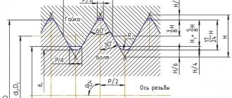
Application of pitch thread
Modular and pitch threads are used on units where it is necessary to ensure motion transmission. These are worm and worm-gear gears, which are used:
- in mechanical jacks;
- press;
- lifts;
- extruders.
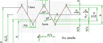
This type of thread ensures reliable engagement of the gear teeth with the worm. A similar result can be achieved by setting the pitch profile to 40 degrees (for comparison, for a metric thread it is 60 degrees).
Measuring rivets
Rivets are a kind of fasteners consisting of two parts: a head and a mandrel. The cap is the short side that needs to be measured for its length and diameter. The mandrel is the long, thin end that comes off the rivet during the installation process.
First of all, you need to place the head into the round holes on a special rivet gauge. The holes have different diameters into which rivets fit. When they are inserted into the hole, the cap should fit snugly.
If there is a gap, the size is too large for the rivet. In the opposite situation it is too small. Using the selection method, you need to determine which size most accurately reflects the parameters of the fastener.
Next you need to measure the length of the rivet. To do this, you need to attach the cap to the open upper areas. Make sure that the washer or flange of the rivet is pressed well.
Pitch thread cutting technology
Pitch threads of different sizes are cut:
- cutters on screw-cutting lathes;
- modular cutters on milling machines;
- finger cutters.
Thread cutting on a lathe allows you to achieve high precision results, but does not guarantee sufficient productivity. In this way, pitch threads are cut on worm shafts, which must be characterized by high accuracy of motion transmission. The method is used in small-scale production and in private workshops.
Using a milling machine allows you to achieve higher productivity when cutting threads. The cutter is installed so that its axis of rotation intersects the longitudinal axis of the workpiece shaft at an angle of 90 degrees. To improve the quality of the notch, it is cut in several passes. Before starting work, the milling machine is set up according to the data from the tables, which give the dimensions of the pitch threads. These parameters allow you to install the required set of gears on a screw-cut guitar with specified gear ratios.
Finger cutters are suitable for cutting pitch threads on large items. To apply a pitch notch, special milling heads with an individual cutter drive are installed on the machine. The first pass is performed with a slotted finger cutter of a straight-through profile, with a profile angle of 35 degrees.
Size chart for cutting pitch threads on a machine
Basic rules for designating pitch threads
Designations in connections with pitch threads are indicated in GOST standards. Each of them contains the following elements:
- a letter indicating that the thread belongs to a certain type;
- size in pitches;
- thread pitch size;
- direction (left - L or right - RH);
- tolerance field dimensions;
- make-up length.
The value of the tolerance field is indicated by several letters and numbers. The former indicate the size of the deviation, the latter indicate the accuracy class. In the first place are symbols characterizing the average diameter, in the second place are symbols relating to the outer diameter. If the dimensions match, only one designation is applied. To indicate the make-up length, three Latin letters are used, with the letter N corresponding to normal length, S to short, L to long.
The rules for applying symbols indicating the main dimensions and other characteristics of pitch threads are given in the form of tables in GOST 24705-2004 and GOST 16093. In 2005, additions were made to the text by adding the main provisions of the ISO 965-1 and ISO 965-3 standards. The pitch system is used in North American countries, and its characteristics are specified in the international standard ANSIB1.9.