BASIC PROVISIONS OF THE PERMISSION SYSTEM
1.1. The designations adopted in this standard are given in table. 1:
Table 1
| Designation | Name |
| d | Outer diameter of male thread (bolt) |
| d1 | Internal diameter of external thread |
| d2 | Average diameter of external thread |
| D | Outer diameter of internal thread (nut) |
| D1 | Inner diameter of female thread |
| D2 | Average internal thread diameter |
| P | Thread pitch |
| H | Height of the original triangle |
| R min | Smallest root radius of external thread |
| S | Group make-up lengths are short |
| N | Group make-up lengths are normal |
| L | Group make-up lengths are long |
| Td ; | Diameter tolerances d , |
| es | Upper deviation of external thread diameters |
| ES | Upper deviation of internal thread diameters |
| ei | Lower deviation of external thread diameters |
| EI | Lower deviation of internal thread diameters |
1.2. The thread tolerance system provides:
thread diameter tolerances;
position of tolerance fields for thread diameters;
classification of make-up lengths;
thread tolerance fields and their selection taking into account make-up lengths.
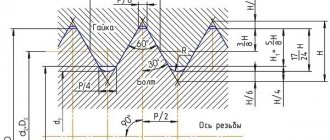
1.3. Schemes of tolerance fields for external and internal threads in clearance fits are shown in Fig. 1.
Crap. 1
Deviations are measured from the nominal thread profile in the direction perpendicular to the thread axis.
1.4. Tolerances of thread diameters are established according to degrees of accuracy, indicated by numbers. The degrees of accuracy of thread diameters are given in table. 2.
Diameter tolerances d
and
D
are not installed.
Tolerances for the average thread diameter are cumulative.
table 2
| Type of thread | Thread diameter | Degree of accuracy |
| External thread | d | 4; 6; 8 |
| d2 | 3; 4; 5; 6; 7; 8; 9; 10* | |
| Internal thread | D2 | 4; 5; 6; 7; 8; 9* |
| D1 | 4; 5; 6; 7; 8 |
*Only for threads on plastic parts.
1.5. The position of the thread diameter tolerance field is determined by the main deviation (upper es for external threads and lower EI for internal threads) and is designated by a letter of the Latin alphabet, lowercase for external threads and uppercase for internal threads.
The positions of the tolerance fields are shown in Fig. 1 and in table. 3.
Table 3
| Type of thread | Thread diameter | Degree of accuracy |
| External thread | d | d; e; f; g; h |
| d2 | d; e; f; g; h | |
| Internal thread | D2 | E; F; G; H |
| D1 | E; F; G; H |
Notes:
1. Upper diameter deviation d 1
must correspond to the main diameter deviation
d 2 .
2. Lower diameter deviation D
must correspond to the main diameter deviation
D 2
.
3. The main deviations E and F are established only for special applications with significant thicknesses of the protective coating layer.
1.6. Make-up lengths are divided into three groups: short S
, normal
N
and long
L.
1.7. The tolerance field of the thread diameter is formed by a combination of tolerance and basic deviation. The thread tolerance field is formed by combining the tolerance field of the average diameter with the tolerance field of the diameter of the protrusions (diameters d
or
D1
).
1.8. Calculation formulas and rules for rounding numerical values of tolerances, main deviations and make-up lengths are given in Appendix 1.
Geometric parameters
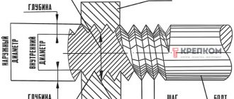
Let's consider the geometric parameters that characterize the main elements of metric threads.
- The nominal thread diameter is designated by the letters D and d. In this case, the letter D refers to the nominal diameter of the external thread, and the letter d refers to a similar parameter of the internal thread.
- The average diameter of the thread, depending on its external or internal location, is designated by the letters D2 and d2.
- The internal diameter of the thread, depending on its external or internal location, is designated D1 and d1.
- The inside diameter of the bolt is used to calculate the stresses created in the structure of such a fastener.
- The thread pitch characterizes the distance between the crests or valleys of adjacent threaded turns. For a threaded element of the same diameter, a basic pitch is distinguished, as well as a thread pitch with reduced geometric parameters. The letter P is used to denote this important characteristic.
- The thread lead is the distance between the crests or valleys of adjacent threads formed by the same helical surface. The progress of the thread, which is created by one screw surface (single-start), is equal to its pitch. In addition, the value to which the thread stroke corresponds characterizes the amount of linear movement of the threaded element performed by it per revolution.
- A parameter such as the height of the triangle that forms the profile of the threaded elements is designated by the letter H.
Geometric parameters of the main metric thread profile
Table of metric thread diameter values (all parameters are indicated in millimeters)
Metric thread diameters (mm)
Complete table of metric threads according to GOST 24705-2004 (all parameters are indicated in millimeters)
Complete table of metric threads according to GOST 24705-2004
The main parameters of metric threads are specified in several regulatory documents.
GOST 8724
This standard contains requirements for the parameters of the thread pitch and its diameter. GOST 8724, the current version of which came into force in 2004, is an analogue of the international standard ISO 261-98. The requirements of the latter apply to metric threads with a diameter of 1 to 300 mm. Compared to this document, GOST 8724 is valid for a wider range of diameters (0.25–600 mm). At the moment, the current edition of GOST 8724 2002, which came into force in 2004 instead of GOST 8724 81. It should be borne in mind that GOST 8724 regulates certain parameters of metric threads, the requirements for which are also specified by other thread standards. The convenience of using GOST 8724 2002 (as well as other similar documents) is that all the information in it is contained in tables, which include metric threads with diameters within the above range. Both left-handed and right-handed metric threads must meet the requirements of this standard.
GOST 24705 2004
This standard stipulates what basic dimensions a metric thread should have. GOST 24705 2004 applies to all threads, the requirements for which are regulated by GOST 8724 2002, as well as GOST 9150 2002.
GOST 9150
This is a regulatory document that specifies the requirements for the metric thread profile. GOST 9150, in particular, contains data on what geometric parameters the main threaded profile of various standard sizes must correspond to. The requirements of GOST 9150, developed in 2002, as well as the two previous standards, apply to metric threads, the turns of which rise from the left upward (right-handed type), and to those whose helical line rises to the left (left-handed type). The provisions of this regulatory document closely echo the requirements given by GOST 16093 (as well as GOSTs 24705 and 8724).
GOST 16093
This standard specifies the tolerance requirements for metric threads. In addition, GOST 16093 prescribes how metric type threads should be designated. GOST 16093 in its latest edition, which came into force in 2005, includes the provisions of the international standards ISO 965-1 and ISO 965-3. Both left-hand and right-hand threads fall under the requirements of such a regulatory document as GOST 16093.
The standardized parameters specified in the metric thread tables must correspond to the thread dimensions in the drawing of the future product. The choice of the tool with which it will be cut should be determined by these parameters.
TOLERANCES
3.1. The numerical values of the tolerances for the diameters of external and internal threads must correspond to those indicated in the table. 4 - 6.
Table 4
Diameter tolerances d
and
D 1
| Step R , mm | External thread | Internal thread | ||||||
| Degree of accuracy | ||||||||
| 4 | 6 | 8 | 4 | 5 | 6 | 7 | 8 | |
| Tolerance, µm | ||||||||
| Td _ | T D 1 | |||||||
| 0,2 | 36 | 56 | — | 38 | 48 | 60 | — | — |
| 0,25 | 42 | 67 | — | 45 | 56 | 71 | — | — |
| 0,3 | 48 | 75 | — | 53 | 67 | 85 | — | — |
| 0,35 | 53 | 85 | — | 63 | 80 | 100 | — | — |
| 0,4 | 60 | 95 | — | 71 | 90 | 112 | — | — |
| 0,45 | 63 | 100 | — | 80 | 100 | 125 | — | — |
| 0,5 | 67 | 106 | — | 90 | 112 | 140 | 180 | — |
| 0,6 | 80 | 125 | — | 100 | 125 | 160 | 200 | — |
| 0,7 | 90 | 140 | — | 112 | 140 | 180 | 224 | — |
| 0,75 | 90 | 140 | — | 118 | 150 | 190 | 236 | — |
| 0,8 | 95 | 150 | 236 | 125 | 160 | 200 | 250 | 315 |
| 1 | 112 | 180 | 280 | 150 | 190 | 236 | 300 | 375 |
| 1,25 | 132 | 212 | 335 | 170 | 212 | 265 | 335 | 425 |
| 1,5 | 150 | 236 | 375 | 190 | 236 | 300 | 375 | 475 |
| 1,75 | 170 | 265 | 425 | 212 | 265 | 335 | 425 | 530 |
| 2 | 180 | 280 | 450 | 236 | 300 | 375 | 475 | 600 |
| 2,5 | 212 | 335 | 530 | 280 | 355 | 450 | 569 | 710 |
| 3 | 236 | 375 | 600 | 315 | 400 | 500 | 630 | 800 |
| 3,5 | 265 | 425 | 670 | 355 | 450 | 560 | 710 | 900 |
| 4 | 300 | 475 | 750 | 375 | 475 | 600 | 750 | 950 |
| 4,5 | 315 | 500 | 800 | 425 | 530 | 670 | 850 | 1060 |
| 5 | 335 | 530 | 850 | 450 | 560 | 710 | 900 | 1120 |
| 5,5 | 355 | 560 | 900 | 475 | 600 | 750 | 950 | 1180 |
| 6 | 375 | 600 | 950 | 500 | 630 | 800 | 1000 | 1250 |
Table 5
Diameter tolerances d 2
| Nominal thread diameter d , mm | Step R , mm | Degree of accuracy | |||||||
| 3 | 4 | 5 | 6 | 7 | 8 | 9 | 10 | ||
| Tolerance Td2 , µm | |||||||||
| From 1 to 1.4 | 0,2 | 24 | 30 | 38 | 48 | (60) | (75) | — | — |
| 0,25 | 26 | 34 | 42 | 53 | (67) | (85) | — | — | |
| 0,3 | 28 | 36 | 45 | 56 | (71) | (90) | — | — | |
| St. 1.4 to 2.8 | 0,2 | 25 | 32 | 40 | 50 | (63) | (80) | — | — |
| 0,25 | 28 | 36 | 45 | 56 | (71) | (90) | — | — | |
| 0,35 | 32 | 40 | 50 | 63 | 80 | (100) | — | — | |
| 0,4 | 34 | 42 | 53 | 67 | 85 | (106) | — | — | |
| 0,45 | 36 | 45 | 56 | 71 | 90 | (112) | — | — | |
| St. 2.8 to 5.6 | 0,25 | 28 | 36 | 45 | 56 | (71) | — | — | — |
| 0,35 | 34 | 42 | 53 | 67 | 85 | (106) | — | — | |
| 0,5 | 38 | 48 | 60 | 75 | 95 | (118) | — | — | |
| 0,6 | 42 | 53 | 67 | 85 | 106 | (132) | — | — | |
| 0,7 | 45 | 56 | 71 | 90 | 112 | (140) | — | — | |
| 0,75 | 45 | 56 | 71 | 90 | 112 | (140) | — | — | |
| 0,8 | 48 | 60 | 75 | 95 | 118 | 150 | 190 | 236 | |
| St. 5.6 to 11.2 | 0,25 | 32 | 40 | 50 | 63 | (80) | — | — | — |
| 0,35 | 36 | 45 | 56 | 71 | 90 | — | — | — | |
| 0,5 | 42 | 53 | 67 | 85 | 106 | (132) | — | — | |
| 0,75 | 50 | 63 | 80 | 100 | 125 | (160) | — | — | |
| 1 | 56 | 71 | 90 | 112 | 140 | 180 | 224 | 280 | |
| 1,25 | 60 | 75 | 95 | 118 | 150 | 190 | 236 | 300 | |
| 1,5 | 67 | 85 | 106 | 132 | 170 | 212 | 265 | 335 | |
| St. 11.2 to 22.4 | 0,35 | 38 | 48 | 60 | 75 | 95 | — | — | — |
| 0,5 | 45 | 56 | 71 | 90 | 112 | (140) | — | — | |
| 0,75 | 53 | 67 | 85 | 106 | 132 | (170) | — | — | |
| 1 | 60 | 75 | 95 | 118 | 150 | 190 | 236 | 300 | |
| 1,25 | 67 | 85 | 106 | 132 | 170 | 212 | 265 | 335 | |
| 1,5 | 71 | 90 | 112 | 140 | 180 | 224 | 280 | 355 | |
| 1,75 | 75 | 95 | 118 | 150 | 190 | 236 | 300 | 375 | |
| 2 | 80 | 100 | 125 | 160 | 200 | 250 | 315 | 400 | |
| 2,5 | 85 | 106 | 132 | 170 | 212 | 265 | 335 | 425 | |
| St. 22.4 to 45 | 0,5 | 48 | 60 | 75 | 95 | 118 | — | — | — |
| 0,75 | 56 | 71 | 90 | 112 | 140 | (180) | — | — | |
| 1 | 63 | 80 | 100 | 125 | 160 | 200 | 250 | 315 | |
| 1,5 | 75 | 95 | 118 | 150 | 190 | 236 | 300 | 375 | |
| 2 | 85 | 106 | 132 | 170 | 212 | 265 | 335 | 425 | |
| 3 | 100 | 125 | 160 | 200 | 250 | 315 | 400 | 500 | |
| 3,5 | 106 | 132 | 170 | 212 | 265 | 335 | 425 | 530 | |
| 4 | 112 | 140 | 180 | 224 | 280 | 355 | 450 | 560 | |
| 4,5 | 118 | 150 | 190 | 236 | 300 | 375 | 475 | 600 | |
| St. 45 to 90 | 0,5 | 50 | 63 | 80 | 100 | 125 | — | — | — |
| 0,75 | 60 | 75 | 95 | 118 | 150 | — | — | — | |
| 1 | 71 | 90 | 112 | 140 | 180 | 224 | 280 | 355 | |
| 1,5 | 80 | 100 | 125 | 160 | 200 | 250 | 315 | 400 | |
| 2 | 90 | 112 | 140 | 180 | 224 | 280 | 355 | 450 | |
| 3 | 106 | 132 | 170 | 212 | 265 | 335 | 425 | 530 | |
| 4 | 118 | 150 | 190 | 236 | 300 | 375 | 475 | 600 | |
| 5 | 125 | 160 | 200 | 250 | 315 | 400 | 500 | 630 | |
| 5,5 | 132 | 170 | 212 | 265 | 335 | 425 | 530 | 670 | |
| 6 | 140 | 180 | 224 | 280 | 355 | 450 | 560 | 710 | |
| St. 90 to 180 | 0,75 | 63 | 80 | 100 | 125 | 160 | — | — | — |
| 1 | 75 | 95 | 118 | 150 | 190 | — | — | — | |
| 1,5 | 85 | 106 | 132 | 170 | 212 | 265 | 335 | 425 | |
| 2 | 95 | 118 | 150 | 190 | 236 | 300 | 375 | 475 | |
| 3 | 112 | 140 | 180 | 224 | 280 | 355 | 450 | 560 | |
| 4 | 125 | 160 | 200 | 250 | 315 | 400 | 500 | 630 | |
| 6 | 150 | 190 | 236 | 300 | 375 | 475 | 600 | 750 | |
| St. 180 to 355 | 1,5 | 90 | 112 | 140 | 180 | 224 | 280 | 355 | — |
| 2 | 106 | 132 | 170 | 212 | 265 | 335 | 425 | 530 | |
| 3 | 125 | 160 | 200 | 250 | 315 | 400 | 500 | 630 | |
| 4 | 140 | 180 | 224 | 280 | 355 | 450 | 560 | 710 | |
| 6 | 160 | 200 | 250 | 315 | 400 | 500 | 630 | 800 | |
| St. 355 to 600 | 2 | 112 | 140 | 180 | 224 | 280 | 355 | 450 | — |
| 4 | 150 | 190 | 236 | 300 | 375 | 475 | 600 | 750 | |
| 6 | 170 | 212 | 265 | 335 | 425 | 530 | 670 | 850 | |
Note. The values indicated in brackets should not be used if possible.
Table 6
Diameter tolerances D 2
| Nominal thread diameter d , mm | Step R , mm | Degree of accuracy | ||||||
| 4 | 5 | 6 | 7 | 8 | 9 | |||
| Tolerance TD2 , µm | ||||||||
| From 1 to 1.4 | 0,2 | 40 | 50 | 63 | — | — | — | |
| 0,25 | 45 | 56 | 71 | — | — | — | ||
| 0,3 | 48 | 60 | 75 | — | — | — | ||
| St. 1.4 to 2.8 | 0,2 | 42 | 53 | 67 | — | — | — | |
| 0,25 | 48 | 60 | 75 | — | — | — | ||
| 0,35 | 53 | 67 | 85 | — | — | — | ||
| 0,4 | 56 | 71 | 90 | — | — | — | ||
| 0,45 | 60 | 75 | 95 | — | — | — | ||
| St. 2.8 to 5.6 | 0,25 | 48 | 60 | 75 | — | — | — | |
| 0,35 | 56 | 71 | 90 | — | — | — | ||
| 0,5 | 63 | 80 | 100 | 125 | — | — | ||
| 0,6 | 71 | 90 | 112 | 140 | — | — | ||
| 0,7 | 75 | 95 | 118 | 150 | — | — | ||
| 0,75 | 75 | 95 | 118 | 150 | — | — | ||
| 0,8 | 80 | 100 | 125 | 160 | 200 | 250 | ||
| St. 5.6 to 11.2 | 0,25 | 53 | 67 | 85 | — | — | — | |
| 0,35 | 60 | 75 | 95 | — | — | — | ||
| 0,5 | 71 | 90 | 112 | 140 | — | — | ||
| 0,75 | 85 | 106 | 132 | 170 | — | — | ||
| 1 | 95 | 118 | 150 | 190 | 236 | 300 | ||
| 1,25 | 100 | 125 | 160 | 200 | 250 | 315 | ||
| 1,5 | 112 | 140 | 180 | 224 | 280 | 355 | ||
| St. 11.2 to 22.4 | 0,35 | 63 | 80 | 100 | — | — | — | |
| 0,5 | 75 | 95 | 118 | 150 | — | — | ||
| 0,75 | 90 | 112 | 140 | 180 | — | — | ||
| 1 | 100 | 125 | 160 | 200 | 250 | 315 | ||
| 1,25 | 112 | 140 | 180 | 224 | 280 | 355 | ||
| 1,5 | 118 | 150 | 190 | 236 | 300 | 375 | ||
| 1,75 | 125 | 160 | 200 | 250 | 315 | 400 | ||
| 2 | 132 | 170 | 212 | 265 | 335 | 425 | ||
| 2,5 | 140 | 180 | 224 | 280 | 355 | 450 | ||
| St. 22.4 to 45 | 0,5 | 80 | 100 | 125 | — | — | — | |
| 0,75 | 95 | 118 | 150 | 190 | — | — | ||
| 1 | 106 | 13,2 | 170 | 212 | 265 | 335 | ||
| 1,5 | 125 | 160 | 200 | 250 | 315 | 400 | ||
| 2 | 140 | 180 | 224 | 280 | 355 | 450 | ||
| 3 | 170 | 212 | 265 | 335 | 425 | 530 | ||
| 3,5 | 180 | 224 | 280 | 355 | 450 | 560 | ||
| 4 | 190 | 236 | 300 | 375 | 475 | 600 | ||
| 4,5 | 200 | 250 | 315 | 400 | 500 | 630 | ||
| St. 45 to 90 | 0,5 | 85 | 106 | 132 | — | — | — | |
| 0,75 | 100 | 125 | 160 | — | — | — | ||
| 1 | 118 | 150 | 190 | 236 | 300 | 375 | ||
| 1,5 | 132 | 170 | 212 | 265 | 335 | 425 | ||
| 2 | 150 | 190 | 236 | 300 | 375 | 475 | ||
| 3 | 180 | 224 | 280 | 355 | 450 | 560 | ||
| 4 | 200 | 250 | 315 | 400 | 500 | 630 | ||
| 5 | 212 | 265 | 335 | 425 | 530 | 670 | ||
| 5,5 | 224 | 280 | 355 | 450 | 560 | 710 | ||
| 6 | 236 | 300 | 375 | 475 | 600 | 750 | ||
| St. 90 to 180 | 0,75 | 106 | 132 | 170 | — | — | — | |
| 1 | 125 | 160 | 200 | 250 | — | — | ||
| 1,5 | 140 | 180 | 224 | 280 | 355 | 450 | ||
| 2 | 160 | 200 | 250 | 315 | 400 | 500 | ||
| 3 | 190 | 236 | 300 | 375 | 475 | 600 | ||
| 4 | 212 | 265 | 335 | 425 | 530 | 670 | ||
| 6 | 250 | 315 | 400 | 500 | 630 | 800 | ||
| St. 180 to 355 | 1,5 | 150 | 190 | 236 | 300 | 375 | — | |
| 2 | 180 | 224 | 280 | 355 | 450 | 560 | ||
| 3 | 212 | 265 | 335 | 425 | 530 | 670 | ||
| 4 | 236 | 300 | 375 | 475 | 600 | 750 | ||
| 6 | 265 | 335 | 425 | 530 | 670 | 850 | ||
| St. 355 to 600 | 2 | 190 | 236 | 300 | 375 | 475 | — | |
| 4 | 250 | 315 | 400 | 500 | 630 | 800 | ||
| 6 | 280 | 355 | 450 | 560 | 710 | 900 | ||
MAIN DEVIATIONS
4.1. The numerical values of the main deviations of the diameters of external and internal threads must correspond to those indicated in the table. 7.
Table 7
| Step P , mm | External thread | Internal thread | |||||||
| Thread diameter | |||||||||
| d ; d 2 | D1 ; | ||||||||
| Main deviation, µm | |||||||||
| es | EI | ||||||||
| d | e | f | g | h | E | F | G | H | |
| 0,2 | — | — | -32 | -17 | 0 | — | +32 | +17 | 0 |
| 0,25 | — | — | -33 | -18 | 0 | — | +33 | +18 | 0 |
| 0,3 | — | — | -33 | -18 | 0 | — | +33 | +18 | 0 |
| 0,35 | — | — | -34 | -19 | 0 | — | +34 | +19 | 0 |
| 0,4 | — | — | -34 | -19 | 0 | — | +34 | +19 | 0 |
| 0,45 | — | — | -35 | -20 | 0 | — | +35 | +20 | 0 |
| 0,5 | — | -50 | -36 | -20 | 0 | +50 | +36 | +20 | 0 |
| 0,6 | — | -53 | -36 | -21 | 0 | +53 | +36 | +21 | 0 |
| 0,7 | — | -56 | -38 | -22 | 0 | +56 | +38 | +22 | 0 |
| 0,75 | — | -56 | -38 | -22 | 0 | +56 | +38 | +22 | 0 |
| 0,8 | — | -60 | -38 | -24 | 0 | +60 | +38 | +24 | 0 |
| 1 | -90 | -60 | -40 | -26 | 0 | +60 | +40 | +26 | 0 |
| 1,25 | -95 | -63 | -42 | -28 | 0 | +63 | +42 | +28 | 0 |
| 1,5 | -95 | -67 | -45 | -32 | 0 | +67 | +45 | +32 | 0 |
| 1,75 | -100 | -71 | -48 | -34 | 0 | +71 | +48 | +34 | 0 |
| 2 | -100 | -71 | -52 | -38 | 0 | +71 | +52 | +38 | 0 |
| 2,5 | -106 | -80 | -58 | -42 | 0 | +80 | — | +42 | 0 |
| 3 | -112 | -85 | -63 | -48 | 0 | +85 | — | +48 | 0 |
| 3,5 | -118 | -90 | — | -53 | 0 | +90 | — | +53 | 0 |
| 4 | -125 | -95 | — | -60 | 0 | +95 | — | +60 | 0 |
| 4,5 | -132 | -100 | — | -63 | 0 | +100 | — | +63 | 0 |
| 5 | -132 | -106 | — | -71 | 0 | +106 | — | +71 | 0 |
| 5,5 | -140 | -112 | — | -75 | 0 | +112 | — | +75 | 0 |
| 6 | -150 | -118 | — | -80 | 0 | +118 | — | +80 | 0 |
Other GOSTs
GOST 25346-2013 Basic standards of interchangeability. Product characteristics are geometric. Tolerance system for linear dimensions. Basic provisions, tolerances, deviations and fits GOST 25347-2013 Basic standards of interchangeability. Product characteristics are geometric. Tolerance system for linear dimensions. Tolerance ranges, maximum deviations of holes and shafts GOST R 53090-2008 Basic norms of interchangeability. Product characteristics are geometric. Requirements for maximum material, minimum material and interaction GOST R 53442-2015 Basic standards of interchangeability. Product characteristics are geometric. Setting geometric tolerances. Tolerances of shape, orientation, location and runout GOST R 53089-2008 Basic norms of interchangeability. Product characteristics are geometric. Establishment of positional tolerances GOST R 50536-93 Basic standards of interchangeability. Low wedge keys with and without a head and keyways. Dimensions and tolerances GOST 29175-91 Basic standards of interchangeability. Low prismatic keys and keyways. Dimensions and tolerances GOST R ISO 3898-2016 Fundamentals of design of building structures. Names and designations of physical quantities GOST 33542-2015 Fundamental principles and safety principles for the human-machine interface, implementation and identification. Identification of electrical equipment terminals, ends of conductors and conductors GOST 17064-71 Main functional units, accessories and auxiliary devices of gamma devices. Terms and definitions GOST 9330-2016 Basic connections of parts made of wood and wood materials. Types and sizes GOST 30391-95 Basic principles of safety of electrical equipment used in medical practice GOST R 50326-92 Basic principles of safety of electrical equipment used in medical practice GOST 24705-2004 Basic standards of interchangeability. Metric thread. Main Dimensions
MAKE-UP LENGTHS
5.1. Make-up lengths related to S
,
N
and
L
must correspond to those indicated in the table. 8.
Table 8
mm
| Nominal thread diameter d | Step P | Make-up length | ||
| S | N | L | ||
| From 1 to 1.4 | 0,2 | Up to 0.5 | St. 0.5 to 1.4 | St. 1.4 |
| 0,2,5 | » 0,6 | » 0,6 » 1,7 | » 1,7 | |
| 0,3 | » 0,7 | » 0,7 » 2 | » 2 | |
| St. 1.4 to 2.8 | 0,2 | Up to 0.5 | St. 0.5 to 1.5 | St. 1.5 |
| 0,25 | » 0,6 | » 0,6 » 1,9 | » 1,9 | |
| 0,35 | » 0,8 | » 0,8 » 2,6 | » 2,6 | |
| 0,4 | » 1 | » 1 » 3 | » 3 | |
| 0,45 | » 1,3 | » 1,3 » 3,8 | » 3,8 | |
| St. 2.8 to 5.6 | 0,25 | Up to 0.7 | St. 0.7 to 2.1 | St. 2.1 |
| 0,35 | » 1 | » 1 » 3 | » 3 | |
| 0,5 | » 1,5 | » 1,5 » 4,5 | » 4,5 | |
| 0,6 | » 1,7 | » 1,7 » 5 | » 5 | |
| 0,7 | » 2 | » 2 » 6 | » 6 | |
| 0,75 | » 2,2 | » 2,2 » 6,7 | » 6,7 | |
| 0,8 | » 2,5 | » 2,5 » 7,5 | » 7,5 | |
| St. 5.6 to 11.2 | 0,25 | Up to 0.8 | St. 0.8 to 2.4 | St. 2.4 |
| 0,35 | » 1,1 | » 1,1 » 3,4 | » 3,4 | |
| 0,5 | » 1,6 | » 1,6 » 4,7 | » 4,7 | |
| 0,75 | » 2,4 | » 2,4 » 7,1 | » 9 | |
| 1 | » 3 | » 3 » 9 | » 7,1 | |
| 1,25 | » 4 | » 4 » 12 | » 12 | |
| 1,5 | » 5 | » 5 » 15 | » 15 | |
| St. 11.2 to 22.4 | 0,35 | Up to 1.3 | St. 1.3 to 3.8 | St. 3.8 |
| 0,5 | » 1,8 | » 1,8 » 5,5 | » 5,5 | |
| 0,75 | » 2,8 | » 2,8 » 8 | » 8,3 | |
| 1 | » 3,8 | » 3,8 » 11 | » 11 | |
| 1,25 | » 4,5 | » 4,5 » 13 | » 13 | |
| 1,5 | » 5,6 | » 5,6 » 16 | » 16 | |
| 1,75 | » 6 | » 6 » 18 | » 18 | |
| 2 | » 8 | » 8 » 24 | » 24 | |
| 2,5 | » 10 | » 10 » 30 | » 30 | |
| St. 22.4 to 45 | 0,5 | Up to 2.1 | St. 2.1 to 6.3 | St. 6.3 |
| 0,75 | » 3,1 | » 3,1 » 9,5 | » 9,5 | |
| 1 | » 4 | » 4 » 12 | » 12 | |
| 1,5 | » 6,3 | » 6,3 » 19 | » 19 | |
| 2, | » 8,5 | » 8,5 » 25 | » 25 | |
| 3 | » 12 | » 12 » 36 | » 36 | |
| 3,5 | » 15 | » 15 » 45 | » 45 | |
| 4 | » 18 | » 18 » 53 | » 53 | |
| 4,5 | » 21 | » 21 » 63 | » 63 | |
| St. 45 to 90 | 0,5 | Up to 2.4 | St. 2.4 to 7.1 | St. 7.1 |
| 0,75 | » 3,6 | » 3,6 » 11 | » 11 | |
| 1 | » 4,8 | » 4,8 » 14 | » 14 | |
| 1,5 | » 7,5 | » 7,5 » 22 | » 22 | |
| 2 | » 9,5 | » 9,5 » 28 | » 28 | |
| 3 | » 15 | » 15 » 45 | » 45 | |
| 4 | » 19 | » 19 » 56 | » 56 | |
| 5 | » 24 | » 24 » 71 | » 71 | |
| 5,5 | » 28 | » 28 » 85 | » 85 | |
| 6 | » 32 | » 32 » 95 | » 95 | |
| St. 90 to 180 | 0,75 | Up to 4.2 | St. 4.2 to 12 | St. 12 |
| 1 | » 5,6 | » 5,6 » 16 | » 16 | |
| 1,5 | » 8,3 | » 8,3 » 25 | » 25 | |
| 2 | » 12 | » 12 » 36 | » 36 | |
| 3 | » 18 | » 18 » 53 | » 53 | |
| 4 | » 24 | » 24 » 71 | » 71 | |
| 6 | » 36 | » 36 » 106 | » 106 | |
| St. 180 to 355 | 1,5 | Up to 9.5 | St. 9.5 to 28 | St. 28 |
| 2 | » 13 | » 13 » 38 | » 38 | |
| 3 | » 20 | » 20 » 60 | » 60 | |
| 4 | » 26 | » 26 » 80 | » 80 | |
| 6 | » 40 | » 40 » 118 | » 118 | |
| St. 355 to 600 | 2 | Up to 15 | St. 15 to 45 | St. 45 |
| 4 | » 29 | » 29 » 87 | » 87 | |
| 6 | » 43 | » 43 » 130 | » 130 | |
5.2. The thread tolerance, unless otherwise specified, refers to the largest normal make-up length indicated in the table. 8, or to the entire thread length if it is less than the longest normal make-up length.
Damn.5
Damn.5
Table 4
| Thread pitch, mm | Maximum deviations of half the profile angle, min, |
| 0,20; 0,25 | ±70 |
| 0,30; 0,35; 0,40 | ±50 |
| 0,45; 0,50; 0,60 | ±35 |
| 0,70; 0,75; 0,80 | ±30 |
| 1,00; 1,25; 1,50 | ±25 |
| 1,75; 2,00; 2,50; 3,00 | ±20 |
| 3,50; 4,00; 4,50; 5,00; 5,50; 6,00 | ±15 |
Note. The tolerance is assumed to be 10% of the tolerance for the average thread diameter of accuracy degree 5 for pitches up to 0.4 mm and 8% for pitches over 0.4 mm.
12. The maximum deviations of the thread pitch of taps of accuracy classes 1, 2, 3 and 4 must correspond to those indicated in Table 5.
Table 5
| Thread pitch, mm | Measurement length in number of steps | Maximum deviations of the thread pitch, µm, for an accuracy class tap | |
| 1, 2, 3 | 4 | ||
| 0,20; 0,25; 0,30; 0,35; 0,40; 0,45; 0,50; 0,60 | 12 | ±8 | ±25 |
| 0,70; 0,75; 0,80; 1,00; 1,25 | 9 | +8 | ±35 |
| 1,50 | 7 | +8 | ±45 |
| 1,75 | +9 | ||
| 2,00; 2,50 | +10 | ||
| 3,00 | ±12 | ||
| 3,50 | ±13 | ±50 | |
| 4,00 | ±14 | ±60 | |
| 4,50 | ±15 | ±60 | |
| 5,00 | ±16 | ±70 | |
| 5,50 | ±17 | ±80 | |
| 6,00 | ±18 | ||
Notes.
1. The pitch tolerance should not exceed 10% of the tolerance for the average thread diameter of accuracy degree 5.
2. The length of the measurement is taken to be no more than 50% of the length of the working part of the tap for pitches up to 1.5 mm and 7 steps for thread pitches over 1.5 mm.
3. The maximum step deviation for any number of steps is set equal to ±0.05% of the base length, but not less than ±0.008 mm.
THREAD SHAPE
6.1. The actual profile of the external thread root should not extend beyond the flat cut line at any point at a distance from the vertex of the original triangle.
6.2. With a rounded external thread root, the radius of curvature of the actual profile at no point should be less than 0.1 R
(Fig. 2).
Numerical values of the smallest radii of curvature of the root of the external thread ( R
min) must correspond to those indicated in the table. 9.
Crap. 2
6.3. If there are high requirements for thread strength, the smallest radius of curvature of the actual root profile of the external thread R
min=0.125
R
(Table 9).
Table 9
mm
| Step P | R min= | R min= | Step P | R min= | R min= | Step P | R min= | R min= |
| 0,2 | 0,020 | 0,025 | 0,75 | 0,075 | 0,094 | 3,5 | 0,350 | 0,438 |
| 0,25 | 0,025 | 0,031 | 0,8 | 0,080 | 0,100 | 4 | 0,400 | 0,500 |
| 0,3 | 0,030 | 0,038 | 1 | 0,100 | 0,125 | 4,5 | 0,450 | 0,562 |
| 0,35 | 0,035 | 0,044 | 1,25 | 0,125 | 0,156 | 5 | 0,500 | 0,625 |
| 0,4 | 0,040 | 0,050 | 1,5 | 0,150 | 0,188 | 5,5 | 0,550 | 0,688 |
| 0,45 | 0,045 | 0,056 | 1,75 | 0,175 | 0,219 | 6 | 0,600 | 0,750 |
| 0,5 | 0,050 | 0,062 | 2 | 0,200 | 0,250 | |||
| 0,6 | 0,060 | 0,075 | 2,5 | 0,250 | 0,312 | |||
| 0,7 | 0,070 | 0,088 | 3 | 0,300 | 0,375 |
6.4. With a flat-cut form of the external thread cavity, the real profile of the cavity should be located between the flat cut lines at a distance and from the vertex of the original triangle (Fig. 3).
6.5. The actual profile of the internal thread cavity at no point should not extend beyond the flat cut line at a distance from the vertex of the original triangle (Fig. 4).
Crap. 3
Crap. 4
TOLERANCE FIELDS
7.1. The tolerance fields of external and internal threads established in accuracy classes (fine, medium and coarse) must correspond to those indicated in table. 10 and table. eleven.
Table 10
| Accuracy class | Make-up length | |||||||||
| S | N | L | ||||||||
| External thread tolerance field | ||||||||||
| Accurate | (3h4h) | 4g | 4h | (5h4h) | ||||||
| Average | 5g6g | (5h6h) | 6d | 6e | 6f | 6g | ||||
*Only for thread pitch P
³0.8 mm.
For threads with a pitch P
<0.8 mm, a tolerance field of 8h6h is applied.
Table 11
6H
| Accuracy class | Make-up length | |||||
| S | N | L | ||||
| Internal thread tolerance field | ||||||
| Accurate | 4H | 4N5N | 6H | |||
| 5H | ||||||
| Average | (5G) | 5H | 6G | |||
Notes to the table 10 and :
1. Tolerance fields enclosed in boxes should be used preferentially.
2. The use of tolerance fields enclosed in brackets should be limited as much as possible.
3. At make-up lengths S
and
L
, it is allowed to use tolerance fields established for make-up lengths
N.
4. In justified cases, it is allowed to use thread tolerance fields formed by other combinations of tolerance fields for the average diameter and diameters of thread protrusions from those given in Table. 10 and , for example:
for external thread - 4h6h; 8h6h;
for internal thread - 5Н6Н.
7.2. Tolerance fields for external and internal threads indicated in table. 10 and , are a restrictive selection from the entire set of tolerance fields, which can be obtained by various combinations of degrees of accuracy according to table. 2 and the main deviations according to table. 3.
Tolerance fields not listed in the table. 10 and , are special. Their use is allowed in technically and economically justified cases, if the tolerance fields according to table. 10 and cannot meet the requirements for the product.
7.3. Limit deviations of external and internal threads corresponding to the tolerance fields specified in table. 10 and are given in mandatory Appendix 2.
7.4. In landings, any combination of tolerance fields for external and internal threads established by this standard is allowed.
It is preferable to combine tolerance fields of the same accuracy class.
Main parameters and areas of application
The most common is metric thread, applied to the external and internal surfaces of a cylindrical shape. This is what is most often used in the manufacture of various types of fasteners:
- anchor and regular bolts;
- nuts;
- hairpins;
- screws, etc.
Conical-shaped parts, on the surface of which a metric type thread is applied, are required in cases where the created connection must be given high tightness. The metric thread profile applied to the conical surfaces allows the formation of tight connections even without the use of additional sealing elements. That is why it is successfully used in the installation of pipelines through which various media are transported, as well as in the manufacture of plugs for containers containing liquid and gaseous substances. It should be kept in mind that the metric thread profile is the same on cylindrical and conical surfaces.
Parameters of tapered metric thread
Types of threads belonging to the metric type are distinguished according to a number of parameters, which include:
- dimensions (diameter and thread pitch);
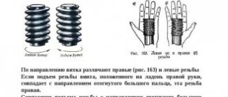
- direction of rise of turns (left or right thread);
- location on the product (internal or external thread).
There are also additional parameters, depending on which metric threads are divided into different types.
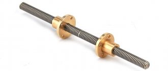
Internal metric thread
External metric thread
This is interesting: Hot metal stamping: the essence and advantages of the technology