How to choose the right drill for a thread - recommendations and possible problems
In the article you will find tables with hole diameters for popular threads - for metric, pipe taps, UNC/UNF, trapezoidal taps, as well as for chipless rolling taps. Information is presented for the main step and the minor step.
We will also touch on the main nuances that may arise when selecting a suitable tool for a rough hole.
Features of choosing the diameter of the drill for the tap:
- Choose a drill suitable for the material being processed. As a rule, a tool made of high-speed steel with the addition of cobalt is sufficient for most threading operations. For hard, complex materials, we recommend using carbide drills.
- The preliminary hole must be additionally countersinked and chamfered. This is necessary for better centering of the tap, as well as for further better entry into the threads of bolts, studs, etc.
- Consider the properties of the material being processed. For brittle and hard metals and for soft and tough metals, the hole diameter will differ. For example, the D of a drill for an M8 thread in soft materials will be 6.8 mm, and for hard metals it is recommended to take a tool with a D of 6.7 mm. To this article we have attached documents from GOST on threaded holes. The sizes of holes of different accuracies are indicated there, as well as the maximum deviations of diameters. In addition, the features and diameters of holes for threading in soft and viscous materials are given. If you have increased requirements for the resulting thread, then you should carefully study the attached documents. If there are no increased requirements for accuracy and quality, then you can use the tables recommended below.
- For brittle metals (cast iron), the dimensions of the rough holes should be reduced by one tenth of a millimeter from the recommended ones.
- The diameters of the holes for regular taps and rolling taps are different, even if they are the same size and thread pitch (you will find a table for chipless taps below in the article).
- All recommendations are reflected in GOST standards, in special tables, following which you can obtain high-quality threads and minimize breakage of taps.
Metric thread pitches GOST 8724-2002
GOST 8724-2002 is a state standard containing standards defining the required parameters of metric threads, including pitch and diameter. Adopted in 2002, with subsequent editions, as an analogue of the international standard ISO 261-98. The GOST text is almost identical to the international text, only the ISO range ranges from 1 to 300 mm. The new edition expanded the range from 0.25 to 600 mm.
The last revision of the text occurred in 2004 and is valid today. The standard establishes the standard value of metric thread pitches in the range from 0.075 to 8 mm.
download GOST 8724-2002 in PDF format from the link .
Read about how to choose a drill for a specific tap in this blog article.
Pre-hole diameter for metric taps
So, let's look at GOST standards for metric threads produced with standard taps.
The most popular sizes: M3, M4, M5, M6, M8, M10 and M12, with a basic pitch.
Brief table for the most popular coarse pitch metric thread sizes:
| Tap (thread/main pitch) | Hole diameter ( drill ⌀), mm |
| M3x0.5 | 2.5 |
| M4x0.7 | 3.3 |
| M5x0.8 | 4.2 |
| M6x.1.0 | 5.0 |
| M8x1.25 | 6.8 |
| M10x1.5 | 8.5 |
| M12x1.75 | 10.2 |
| M14x2.0 | 12.0 |
| M16x2.0 | 14.0 |
| M18x2.5 | 15.4-15.6 |
| M20x2.5 | 17.4-17.6 |
Detailed table of drill sizes for metric threads, main pitch ( DIN 13/GOST 24705) :
| M | Pitch, mm | Int. nut thread diameter, mm (additional according to ISO2 - 6H) | Drill D, mm (according to DIN336) |
| 1 | 0,25 | *0,774 | 0,75 |
| 1,1 | 0,25 | *0,874 | 0,85 |
| 1,2 | 0,25 | *0,974 | 0,95 |
| 1,4 | 0,3 | *1,128 | 1,1 |
| 1,6 | 0,35 | 1,321 | 1,25 |
| 1,8 | 0,35 | 1,521 | 1,45 |
| 2 | 0,4 | 1,679 | 1,6 |
| 2,2 | 0,45 | 1,838 | 1,75 |
| 2,5 | 0,45 | 2,138 | 2,05 |
| 3 | 0,5 | 2,599 | 2,5 |
| 3,5 | 0,6 | 3,010 | 2,9 |
| 4 | 0,7 | 3,422 | 3,3 |
| 4,5 | 0,75 | 3,878 | 3,7 |
| 5 | 0,8 | 4,334 | 4,2 |
| 6 | 1 | 5,153 | 5,0 |
| 7 | 1 | 6,153 | 6,0 |
| 8 | 1,25 | 6,912 | 6,8 |
| 9 | 1,25 | 7,912 | 7,8 |
| 10 | 1,5 | 8,676 | 8,5 |
| 11 | 1,5 | 9,676 | 9,5 |
| 12 | 1,75 | 10,441 | 10,2 |
| 14 | 2 | 12,210 | 12,0 |
| 16 | 2 | 14,210 | 14,0 |
| 18 | 2,5 | 15,744 | 15,5 |
| 20 | 2,5 | 17,744 | 17,5 |
| 22 | 2,5 | 19,744 | 19,5 |
| 24 | 3 | 21,252 | 21,0 |
| 27 | 3 | 24,252 | 24,0 |
| 30 | 3,5 | 26,771 | 26,5 |
| 33 | 3,5 | 29,771 | 29,5 |
| 36 | 4 | 32,270 | 32,0 |
| 39 | 4 | 35,270 | 35,0 |
| 42 | 4,5 | 37,799 | 37,5 |
| 45 | 4,5 | 40,799 | 40,5 |
| 48 | 5 | 43,297 | 43,0 |
| 52 | 5 | 47,297 | 47,0 |
| 56 | 5,5 | 50,796 | 50,5 |
| 60 | 5,5 | 54,796 | 54,5 |
| 64 | 6 | 58,305 | 58,0 |
| 68 | 6 | 62,305 | 62,0 |
*Tolerance range according to ISO1 – 4H.
Detailed table of drill sizes for metric threads fine pitch ( DIN 13/GOST 24705) :
| MxStep | Int. nut thread diameter, mm (additional according to ISO2 - 6H) | Drill D, mm (according to DIN336) | MxStep | Int. nut thread diameter, mm (additional according to ISO2 - 6H) | Drill D, mm (according to DIN336) | |
| 2×0,25 | *1,774 | 1,75 | 24×1 | 23,153 | 23 | |
| 2,2×0,25 | *1,974 | 1,95 | 24×1,5 | 22,676 | 22,5 | |
| 2,3×0,25 | 2,071 | 2,05 | 24×2 | 22,210 | 22 | |
| 2,5×0,35 | *2,184 | 2,15 | 25×1 | 24,153 | 24 | |
| 2,6×0,35 | 2,252 | 2,2 | 25×1,5 | 23,676 | 23,5 | |
| 3×0,35 | *2,684 | 2,65 | 26×1,5 | 24,676 | 24,5 | |
| 3,5×0,35 | *3,184 | 3,15 | 27×1,5 | 25,676 | 25,5 | |
| 4×0,35 | *3,684 | 3,65 | 27×2 | 25,210 | 25,0 | |
| 4×0,5 | 3,599 | 3,5 | 28×1,5 | 26,676 | 26,5 | |
| 5×0,5 | 4,599 | 4,5 | 28×2 | 26,210 | 26,0 | |
| 6×0,5 | 5,599 | 5,5 | 30×1 | 29,153 | 29,0 | |
| 6×0,75 | 5,378 | 5,2 | 30×1,5 | 28,676 | 28,5 | |
| 7×0,75 | 6,378 | 6,2 | 30×2 | 28,210 | 28,0 | |
| 8×0,5 | 7,599 | 7,5 | 32×1,5 | 30,676 | 30,5 | |
| 8×0,75 | 7,378 | 7,2 | 33×1,5 | 31,676 | 31,5 | |
| 8×1 | 7,153 | 7,0 | 33×2 | 31,210 | 31,0 | |
| 9×0,75 | 8,378 | 8,2 | 34×1,5 | 32,676 | 32,5 | |
| 9×1 | 8,153 | 8,0 | 35×1,5 | 33,676 | 33,5 | |
| 10×0,5 | 9,599 | 9,5 | 36×1,5 | 34,676 | 34,5 | |
| 10×0,75 | 9,378 | 9,2 | 36×2 | 34,210 | 34,0 | |
| 10×1 | 9,153 | 9,0 | 36×3 | 33,252 | 33,0 | |
| 10×1,25 | 8,912 | 8,8 | 38×1,5 | 36,676 | 36,5 | |
| 11×1 | 10,153 | 10,0 | 39×1,5 | 37,676 | 37,5 | |
| 12×0,75 | 11,378 | 11,2 | 39×2 | 37,210 | 37,0 | |
| 12×1 | 11,153 | 11,0 | 39×3 | 36,252 | 36,0 | |
| 12×1,25 | 10,912 | 10,8 | 40×1,5 | 38,676 | 38,5 | |
| 12×1,5 | 10,676 | 10,5 | 40×2 | 38,210 | 38,0 | |
| 13×1 | 12,153 | 12,0 | 40×3 | 37,252 | 37,0 | |
| 14×1 | 13,153 | 13,0 | 42×1,5 | 40,676 | 40,5 | |
| 14×1,25 | 12,912 | 12,8 | 42×2 | 40,210 | 40,0 | |
| 14×1,5 | 12,676 | 12,5 | 42×3 | 39,252 | 39,0 | |
| 15×1 | 14,153 | 14,0 | 45×1,5 | 43,676 | 43,5 | |
| 15×1,5 | 13,676 | 13,5 | 45×2 | 43,210 | 43,0 | |
| 16×1 | 15,153 | 15,0 | 45×3 | 42,252 | 42,0 | |
| 16×1,5 | 14,676 | 14,5 | 48×1,5 | 46,676 | 46,5 | |
| 18×1 | 17,153 | 17,0 | 48×2 | 46,210 | 46,0 | |
| 18×1,5 | 16,676 | 16,5 | 48×3 | 45,252 | 45,0 | |
| 18×2 | 16,210 | 16,0 | 50×1,5 | 48,676 | 48,5 | |
| 20×1 | 19,153 | 19,0 | 50×2 | 48,210 | 48,0 | |
| 20×1,5 | 18,676 | 18,5 | 50×3 | 47,252 | 47,0 | |
| 20×2 | 18,210 | 18,0 | 52×1,5 | 50,676 | 50,5 | |
| 22×1 | 21,153 | 21,0 | 52×2 | 50,210 | 50,0 | |
| 22×1,5 | 20,676 | 20,5 | 52×3 | 49,252 | 49,0 | |
| 22×2 | 20,210 | 20,0 | 63×1,5 | 61,676 | 61,5 |
*Tolerance range according to ISO1 – 4H.
Note! There is also another quick method, the so-called “old-fashioned method”, using it you can quickly select a drill for a tap without tables. To do this, you need to subtract its pitch from the nominal diameter of the thread.
Let's look at the method using an example. Let's say you need to cut a thread M10x1.5 .
- Nominal thread diameter 10 mm.
- Step 1.5 mm.
- Subtract the second value from the first: 10-1.5 = 8.5 mm.
- The drill diameter is 8.5 mm.
It is allowed to round the value up. For example, round 9.75 to 9.8. But this will be an approximate value; the “old-fashioned” method is more suitable for domestic needs. For production tasks, it is recommended to rely on tables, GOSTs, taking into account the tolerances and characteristics of the material being processed.
Hole sizes according to GOST
The current state standard was introduced back in 1973, back in the Soviet Union. It is clear that over the past period it has been revised several times, but each time after checks its provisions not only did not change, but were also re-affirmed, since they were recognized as the most rational and still relevant.
The number of the normative act is GOST 19257-73, and it has the following features:
- is a whole set of various documents;
- sets the conditions for strict adherence to geometric parameters, which will ensure strength, wear resistance, and quality of fasteners;
- regulates the processing of several alloys at once - steel, cast iron, copper and aluminum.
How to choose a drill for rolling taps (chipless)
The choice of drill for rolling machines, which are used to extrude threads, has its own characteristics. Metal deformation occurs both in the direction of the hole axis and in the opposite direction. Therefore, the rough hole for rolling is usually drilled larger than for cutting with chips.
For example, to cut M8 with a pitch of 1.25 you need to take a tool with a diameter of 6.8 mm, and to obtain M8x1.25 by rolling (extruding) you need to drill a rough hole ⌀ 7.45 mm.
First, let's look at metric chipless taps.
Table of hole sizes for rolling pins, metric thread, coarse pitch ( DIN 13/GOST 24705):
| M | (additional according to ISO2 - 7H) | ||||
| 1 | 0,25 | *0,785 | 0,89 | 0,91 | 0,9 |
| 1,1 | 0,25 | *0,885 | 0,99 | 1,01 | 1,0 |
| 1,2 | 0,25 | *0,985 | 1,09 | 1,11 | 1,1 |
| 1,4 | 0,3 | *1,142 | 1,24 | 1,27 | 1,25 |
| 1,6 | 0,35 | *1,321 | 1,44 | 1,48 | 1,45 |
| 1,8 | 0,35 | *1,521 | 1,66 | 1,68 | 1,67 |
| 2,0 | 0,4 | *1,679 | 1,84 | 1,86 | 1,85 |
| 2,2 | 0,45 | **1,838 | 2,02 | 2,04 | 2,03 |
| 2,5 | 0,45 | *2,138 | 2,30 | 2,34 | 2,3 |
| 3 | 0,5 | 2,639 | 2,79 | 2,82 | 2,8 |
| 3,5 | 0,6 | 3,050 | 3,24 | 3,28 | 3,25 |
| 4 | 0,7 | 3,466 | 3,69 | 3,73 | 3,7 |
| 4,5 | 0,75 | 3,924 | 4,16 | 4,2 | 4,2 |
| 5 | 0,8 | 4,384 | 4,64 | 4,68 | 4,65 |
| 6 | 1 | 5,217 | 5,51 | 5,59 | 5,55 |
| 7 | 1 | 6,217 | 6,55 | 6,6 | 6,55 |
| 8 | 1,25 | 6,982 | 7,41 | 7,48 | 7,45 |
| 9 | 1,25 | 7,982 | 8,41 | 8,48 | |
| 10 | 1,5 | 8,751 | 9,28 | 9,37 | 9,35 |
| 11 | 1,5 | 9,751 | 10,28 | 10,37 | |
| 12 | 1,75 | 10,531 | 11,16 | 11,25 | 11,2 |
| 14 | 2 | 12,310 | 13,02 | 13,14 | 13,1 |
| 16 | 2 | 14,310 | 15,02 | 15,14 | 15,1 |
| 18 | 2,5 | 15,854 | 16,75 | 16,89 | 16,9 |
| 20 | 2,5 | 17,854 | 18,75 | 18,89 | 18,9 |
*Tolerance range according to ISO1 – 5H. **Tolerance range according to ISO2 – 6H.
Table of hole diameters for rolling taps, metric thread, fine pitch ( DIN 13/GOST 24705):
| MxStep | (additional according to ISO2 - 7H) | |||
| 2×0,25 | *1,785 | 1,9 | 1,91 | |
| 2,2×0,25 | *1,985 | 2,1 | 2,11 | |
| 2,3×0,25 | *2,071 | 2,2 | 2,21 | |
| 2,5×0,35 | 2,201 | 2,36 | 2,38 | 2,37 |
| 2,6×0,35 | 2,252 | 2,46 | 2,48 | 2,47 |
| 3×0,35 | *2,701 | 2,87 | 2,89 | 2,88 |
| 3,5×0,35 | *3,201 | 3,37 | 3,39 | 3,38 |
| 4×0,35 | *3,701 | 3,87 | 3,89 | |
| 4×0,5 | 3,639 | 3,79 | 3,82 | 3,8 |
| 5×0,5 | 4,639 | 4,79 | 4,82 | 4,8 |
| 6×0,5 | **5,599 | 5,8 | 5,83 | 5,8 |
| 6×0,75 | 5,424 | 5,63 | 5,7 | 5,7 |
| 7×0,75 | 6,424 | 6,67 | 6,72 | 6,7 |
| 8×0,5 | **7,599 | 7,8 | 7,83 | |
| 8×0,75 | 7,424 | 7,67 | 7,72 | 7,7 |
| 8×1 | 7,217 | 7,51 | 7,6 | 7,55 |
| 9×0,75 | 8,424 | 8,67 | 8,72 | 8,7 |
| 9×1 | 8,217 | 8,55 | 8,6 | 8,6 |
| 10×0,5 | **9,599 | 9,8 | 9,83 | 9,8 |
| 10×0,75 | 9,424 | 9,67 | 9,72 | 9,7 |
| 10×1 | 9,217 | 9,51 | 9,6 | 9,55 |
| 10×1,25 | 8,982 | 9,41 | 9,48 | 9,45 |
| 11×1 | 10,217 | 10,55 | 10,6 | 10,6 |
| 12×1 | 11,217 | 11,52 | 11,61 | 11,55 |
| 12×1,25 | 10,982 | 11,43 | 11,5 | 11,45 |
| 12×1,5 | 10,751 | 11,29 | 11,38 | 11,35 |
| 14×1 | 13,217 | 13,55 | 13,61 | 13,6 |
| 14×1,25 | 12,982 | 13,43 | 13,5 | 13,45 |
| 14×1,5 | 12,751 | 13,29 | 13,38 | 13,35 |
| 15×1 | 14,217 | 14,55 | 14,61 | 14,6 |
| 15×1,5 | 13,751 | 14,26 | 14,36 | 14,35 |
| 16×1 | 15,217 | 15,55 | 15,61 | 15,6 |
| 16×1,5 | 14,751 | 15,29 | 15,38 | 15,35 |
| 18×1 | 17,217 | 17,55 | 17,61 | 17,6 |
| 18×1,5 | 16,751 | 17,29 | 17,38 | 17,35 |
| 18×2 | 16,310 | 17,02 | 17,14 | 17,1 |
| 20×1 | 19,217 | 19,55 | 19,61 | 19,6 |
| 20×1,5 | 18,751 | 19,29 | 19,38 | 19,35 |
| 20×2 | 18,310 | 19,02 | 19,14 | 19,1 |
| 22×1,5 | 20,751 | 21,26 | 21,36 | |
| 22×2 | 20,310 | 21 | 21,15 | |
| 24×1,5 | 22,751 | 23,26 | 23,38 | |
| 24×2 | 22,310 | 23,01 | 23,16 | 23,1 |
*Tolerance range according to ISO1 – 5H. **Tolerance range according to ISO2 – 6H.
Now let's look at the rollers for inch (pipe) threads.
Table of diameters for Whitworth pipe thread rolling taps ( DIN ISO 228/1):
| G | Threads per inch | |||||
| G 1/16″ | 28 | 7,723 | 6,843 | 7,24 | 7,32 | |
| G 1/8″ | 28 | 9,728 | 8,848 | 9,24 | 9,32 | 9,25 |
| G 1/4″ | 19 | 13,157 | 11,890 | 12,48 | 12,56 | 12,55 |
| G 3/8″ | 19 | 16,662 | 15,395 | 15,99 | 16,06 | 16,06 |
| G 1/2″ | 14 | 20,955 | 19,172 | 20,02 | 20,12 | 20,05 |
| G 5/8″ | 14 | 22,911 | 21,128 | 21,97 | 22,07 | |
| G 3/4″ | 14 | 26,441 | 24,658 | 25,5 | 25,6 | |
| G 7/8″ | 14 | 30,201 | 28,418 | 29,26 | 29,36 | |
| G1″ | 11 | 33,249 | 30,931 | 32,05 | 32,18 | |
| G 1 1/8″ | 11 | 37,897 | 35,579 | 36,7 | 36,83 | |
| G 1 1/4″ | 11 | 41,910 | 39,592 | 40,72 | 40,84 | |
| G 1 3/8″ | 11 | 44,323 | 42,005 | 43,13 | 43,26 | |
| G 1 1/2″ | 11 | 47,803 | 45,485 | 46,61 | 46,74 | |
| G 1 3/4″ | 11 | 53,746 | 51,428 | 52,55 | 52,68 | |
| G 2″ | 11 | 59,614 | 57,296 | 58,42 | 58,55 |
Main settings
Depending on various characteristics, one of the classifications is chosen. Distinctive features:
- measuring system for calculation - Russian GOSTs. The work of all domestic factories for the production of fastening tools is set to millimeters, while inches are actively used abroad;
- how many threads to take for starting - one, two or three - the intensity of twisting and the greatest strength depend on this; the most common are double-threaded;
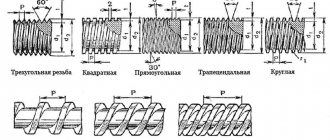
- geometric features of the profile - circle, square, trapezoid, triangle;
- direction of development of turns - right or left;
- where the thread is located in relation to the part - from the outside, as on screws, or from the inside, as on nuts;
- the shape of the surface itself is a cylinder or cone. In other words, is there an extension (for example, a screw or self-tapping screw) to the head, or is the cross-section the same along the entire length, like a screw or bolt;
- the purpose of the product, so that it is clear how and which drills to select for the thread.
According to the above parameters, a number of varieties can be distinguished. Each is designated in drawings and diagrams in a special way. Let's write what the differences are.
- BSW, UTS, NPT – inch;
- M – metric, GOST 9150-2002 is provided for it.
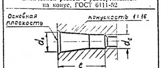
- MK – conical, GOST 6211-81.
- MJ – cylindrical, GOST 6357-81.
- Kr – round, for plumbing.
- Tr – trapezoidal, GOST 9484-81.
- E – with a round profile, Edison.
- S – persistent GOST 10177-82.
- S45 – persistent reinforced.
- G and R – pipe.
This marking not only corresponds to the inscriptions on the drawings, but also forms one part of the nomenclature for numerous fasteners.
Drill diameters for pipe (inch) taps
Pipe thread pre-hole size chart:
| G | Thread pitch, mm | Number of threads per 1 inch | ⌀ threaded drills, mm | ⌀ threaded holes, mm | ||
| Nominal | Limit deviations for accuracy classes | |||||
| A | B | |||||
| G1/8 | 0.907 | 28 | 8.7 | 8.62 | +0.1 | +0.2 |
| G1/4 | 1.337 | 19 | 11.5 | 11.5 | +0.12 | +0.25 |
| G3/8 | 1.337 | 19 | 15 | 15 | +0.12 | +0.25 |
| G1/2 | 1.814 | 14 | 18.75 | 18.68 | +0.14 | +0.28 |
| G5/8 | 1.814 | 14 | 20.75 | 20.64 | +0.14 | +0.28 |
| G3/4 | 1.814 | 14 | 24.25 | 24.17 | +0.14 | +0.28 |
| G7/8 | 1.814 | 14 | 28 | 27.93 | +0.14 | +0.28 |
| G1 | 2.309 | 11 | 30.5 | 30.34 | +0.18 | +0.36 |
| G1 1/8 | 2.309 | 11 | 35 | 35 | +0.18 | +0.36 |
| G1 1/4 | 2.309 | 11 | 39 | 39 | +0.18 | +0.36 |
| G1 3/8 | 2.309 | 11 | 41.5 | 41.41 | +0.18 | +0.36 |
| G1 1/2 | 2.309 | 11 | 45 | 44.9 | +0.18 | +0.36 |
| G1 3/4 | 2.309 | 11 | 51 | 50.84 | +0.18 | +0.36 |
| G2 | 2.309 | 11 | — | 56.7 | +0.18 | +0.36 |
| G2 1/4 | 2.309 | 11 | — | 62.8 | +0.22 | +0.43 |
| G2 1/2 | 2.309 | 11 | — | 72.27 | +0.22 | +0.43 |
| G2 3/4 | 2.309 | 11 | — | 78.62 | +0.22 | +0.43 |
| G3 | 2.309 | 11 | — | 84.97 | +0.22 | +0.43 |
| G3 1/4 | 0.907 | 11 | — | 91.07 | +0.22 | +0.43 |
| G3 1/2 | 1.337 | 11 | — | 97.42 | +0.22 | +0.43 |
| G3 3/4 | 1.337 | 11 | — | 103. 77 | +0.22 | +0.43 |
| G4 | 1.814 | 11 | — | 110. 12 | +0.22 | +0.43 |
| G4 1/2 | 1.814 | 11 | — | 122. 82 | +0.22 | +0.43 |
| G5 | 1.814 | 11 | — | 135. 52 | +0.22 | +0.43 |
| G5 1/2 | 1.814 | 11 | — | 148. 22 | +0.22 | +0.43 |
| G6 | 2.309 | 11 | — | 160. 92 | +0.22 | +0.43 |
Using taps
In actual practice, in production, as well as in various workshops, taps are most often used. They implement the principle of sequential introduction of cutting edges into the body of the workpiece. But there is more than one row of teeth, like a comb. A powerful body is used that is capable of centering the tool inside the hole.
Tap:
a) structural elements: 1 – thread of the threaded part; 2 – square shank for transmitting torque; 3 – cylindrical part of the shank; 4 – groove for collecting chips; 5 – cutting edges (feathers); b) geometric parameters of the cutting part: 1 – front surface facing the part; 2 – cutting edge, triangular teeth; 3 – backed part, rear surface; 4 – reverse part, forming a support; 5 – feather; α – rear angle of the backed part; β – apex angle, it is also called the cutting angle; δ – angle of sharpening of the edges of the cutting blade (triangle); γ – front angle facing the material being removed; c) a tap with a straight chip flute: 1 – groove for collecting chips; d) a tap having a helical flute. Typically found on machine tools with pressurized coolant; e) for cutting blind threads on machines
The choice of one design or another is determined by the characteristics of the process. Most craftsmen use taps with straight flutes in their arsenal. After completing one pass, the tool is removed. Chips and other inclusions that may end up in the hole are removed from it.
One pass does not cut the thread completely. Typically, roughing and finishing taps are used.
Types of thread taps
A crank is used to rotate the tap located in the hole. The design can be very diverse.
Types of cranks for manual tapping of holes
Sequence of tool use
Most often, the kit includes two taps. But to obtain high-quality threads, kits that include three tools can also be used. Some manufacturers, in addition to the parameters of the thread being cut, indicate the letters: A, B, C. Others apply several marks:
- 1 risk on draft;
- 2 risks on the main;
- 3 risks on finishing.
In addition to external designations, the type of tap can be distinguished by a number of characteristics:
- The first pass roughing tool has a minimum diameter. It is enough to measure the outer size using a caliper to find it in the set. The part that goes in first has fine teeth, the tops are cut almost to nothing;
- the second tap in the set has noticeably longer feather combs. The diameter value will be the average of the three. The last teeth will cut the full profile thread;
- In a finishing tap, almost all teeth have the same height. The closing ones do not cut, but calibrate the formed screw grooves in the hole.
General view of the taps from the set
How to choose drills for UNC/UNF taps
Inch cylindrical threads UNC (large) and UNF (fine) are less common in Russia; their profile is similar to the metric 60°, but the size is calculated in inches.
Table of hole diameters for the most common American UNC/ UNF threads:
| Inch UNC thread | |||||||||||||||
| Thread x Threads per inch | Drill diameter, mm | Thread x Threads per inch | Drill diameter, mm | ||||||||||||
| 1/4x20 | 5.1 | 7/8x9 | 19.5 | ||||||||||||
| 5/16x18 | 6.5 | 1x8 | 22.25 | ||||||||||||
| 3/8x16 | 8 | 1 1/8x7 | 25 | ||||||||||||
| 7/16x14 | 9.4 | 1 1/4x7 | 28.25 | ||||||||||||
| 1/2x13 | 10.8 | 1 3/8x6 | 30.75 | ||||||||||||
| 9/16x12 | 12.2 | 1 1/2x6 | 34 | ||||||||||||
| 5/8x11 | 13.6 | 1 3/4x5 | 39.5 | ||||||||||||
| 3/4x10 | 16.5 | 2x4 | 45 | ||||||||||||
pp
| Inch fine thread UNF | |||||||||||||||
| Thread x threads per inch | ⌀ drill, mm | Thread x threads per inch | ⌀ drill, mm | ||||||||||||
| 1/4x28 | 5.5 | 3/4x16 | 17.5 | ||||||||||||
| 5/16x24 | 6.9 | 7/8x14 | 20.5 | ||||||||||||
| 3/8x24 | 8.5 | 1x12 | 23.25 | ||||||||||||
| 7/16x20 | 9.9 | 1 1/8x12 | 26.5 | ||||||||||||
| 1/2x20 | 11.5 | 1 1/4x12 | 29.75 | ||||||||||||
| 9/16x18 | 12.9 | 1 3/8x12 | 33 | ||||||||||||
| 5/8x18 | 14.5 | 1 1/2x12 | 36 | ||||||||||||
End of table
Thread parameters and its varieties
The process of cutting internal grooves in a hole with a tap: 1 – knob; 2 – tap; 3 – part with a prepared hole
It is customary to divide threads by type and purpose. There are several criteria that are used to determine a certain type:
- units. The main world calculus for technology is the SI and the inch system. It is customary to use millimeters or inches. Important!
When creating a pipeline network, inch pipe threads are used ; - Depending on the number of threads being cut, they are usually divided into: single-, double- and triple-start threaded products. Larger quantities are used extremely rarely;
- An important indicator is the type of profile of the groove being cut. The most commonly used is the triangular type. It can have 60⁰ at the top (metric) or 55⁰ - inch. In addition, they produce rectangular (for lead screws and nuts), round (for electric lamps) and trapezoidal (thrust types);
- according to the direction of rotation they are divided into: right (if you look along the axis and move forward, then rotation occurs clockwise), left - twisting is done by rotating counterclockwise;
- it has already been noted that grooves are cut from the outside (external) and inside (thread in the hole);
- according to the shape of the generating surface: cylindrical (distributed everywhere) and conical (used in the manufacture of tightening stoppers);
- The purpose of threaded joints can be different: fastening (connects parts into a single unit); fastening and sealing (not only fixes the parts together, but also prevents the penetration of gases and liquids between the connected products); running gears designed for oriented movement along the axis of the helical surface at a given distance.
Basic parameters of a threaded connection (metric, capital letters indicate the inner surface of the nut, lowercase letters indicate the outer surface of the bolt):
d is the outer diameter of the bolt on the surface of which the thread is cut. Nominal parameter, mm; D – outer diameter of the thread on the nut, mm; d₂ – value of the average diameter on the bolt, mm; D₂ – size of the average diameter of the nut, mm; D₁ – diameter of the nut inside the grooves, mm; d₁ – bolt diameter along the inner surface of the helix, mm; D₁ – minimum diameter of the groove on the nuts, mm; d₃ – minimum bolt diameter along the grooves, mm; P – thread pitch, mm; H – height of the triangle defining the thread profile.
Basic thread types
In practice, metric threads are most often used. It is designated by the letter M (in imported versions it may be indicated by the letter J). Next to it is a number characterizing the nominal diameter of the connection. But in addition to the usual metric versions, a number of special ones are used:
- MK (JK) – metric for cones;
- G or R – inch pipe. For domestic users, the drawings indicate the inch symbol (“) and the inscription pipe;
- E – round with Edison profile used for electric lamps. In the domestic version, it is customary to indicate the nominal diameter and add a round electric lamp. Attention!
In practice, there is no special tool for naming such devices. The helical line is produced by rolling onto thin-walled sheet metal. Similar operations are performed in large enterprises ; - Тr – trapezoidal profile surface. In domestic products, the word trapezoidal must be written with the obligatory indication of the parameters of the trapezoid;
- Kr - the appearance on the market of imported sanitary fittings has led to the appearance of round threads for sanitary fixtures made on the basis of copper alloys. The use of such products is limited, but some may encounter them in everyday practice;
- S and S45 – thrust type of threaded connection profile. Has quite limited use. It is found in machine tools and also on ships. S45 indicates reinforced performance;
- BSW, UTS - this is how inch threads are designated in specifications. BSW is a cylindrical design. UTS – conical view of the helix;
- NPT - for oil workers there is a standard for threaded pipe connections. The inch size is traditionally used here. Depending on the diameter, triangular or rectangular types of profiles can be used.
Main types of threads according to GOST and industry standards
Measuring the outer diameter of a thread
To measure external threads, micrometric instruments are used, the basis of which are microscrews. Control is carried out according to this scheme.
- Microscrews are applied to the thread profile. The position of the instrument is adjusted by rotating the micrometer several times.
- Record the size of the cutting profile for one side. The value is calculated based on the division value on the microscrew scale.
- The micrometer is applied to the opposite end of the profile and its size is calculated.
- The result of measuring the outer diameter of the thread is determined by subtracting the result of the second from the result of the first calculation.
Combination tool
In addition to conventional taps and drills, special combinations are used in practice. With their help, the hole is drilled to the desired size. The same device cuts threads. For light alloys, as well as low-carbon steel, such devices are used not only by craftsmen in their own workshops. They are used in large enterprises where various products have to be mass-produced.
Combination tap-drill
A similar tool is used when it is necessary to slightly increase the diameter of workpieces. Similar operations often have to be performed when working with castings. There are already holes there, obtained through core mixtures. But they often do not have the required shape and size. By using a tap-drill, two operations will be performed at once.
The widespread use of electric screwdrivers in production and at home has led to the creation of special drill taps for this convenient tool. You can purchase entire sets.
Drill bit for screwdriver
Manufacturers write that such products are best used for plastics and aluminum alloys. In fact, if lubricated, such tools do a good job on low-carbon structural steels.
At most large enterprises, the thread cutting procedure is as mechanized as possible. Special machine taps are used. They are distinguished by a long shank, as well as the presence of not only cutting combs. There is also a calibrating part.
Video: how to choose a drill for tapping?
How to do thread cutting?
The procedure for cutting helical grooves in a hole
The work is performed in a certain sequence.
It starts with markings. Using a core, the center of the future hole is marked. Here it is important to mark the markings the first time. It is not allowed to deliver several consecutive blows. Even a slight impact is enough to create a deepening. The drill itself will determine the center of the drill.
You need to drill strictly perpendicular to the surface. Therefore, if conditions permit, you need to use the machine. It will ensure rigid movement of the spindle with the drill. If you have to drill a hole larger than 8 mm, then it is advisable to perform this procedure in several stages. First, a small diameter hole is drilled. Then it is drilled out into a larger one. It happens that you have to drill in three or even five stages, successively increasing the diameter of the hole. At the last stage, use the size required according to the table. Attention! Be sure to use lubricant. It can be applied with a brush, applied from a pipette, or used with a syringe from which the needle has been removed (however, it can also be used with a needle)
.
If it is impossible to use a drilling machine, use hand-held electric drilling machines (drills). Here it is important to strictly maintain the position of the drill relative to the part. To begin work, experienced craftsmen use special jigs that ensure perpendicular entry of the drill. It is important to do the first pass correctly. In the future, larger diameter drills themselves move in the direction of minimal effort
.
To facilitate the entry of the tap into the hole, a chamfer is removed. A small recess performs two functions: it facilitates the introduction of the beginning of the working part of the tool; the lubricant in the conical recess will continue to flow for some time, facilitating the thread cutting process
.
The roughing tap is used first. It is inserted into the knob, then the working part is placed in the hole. You have to lightly press down on the tool to start the formation of a helical groove. You can't be too zealous; you can easily break the tap.
They turn it one turn, and then you need to turn it back a third to break the resulting chips. By rotating in the opposite direction, you can feel when a break occurs.
If you have to cut a thread in a deep hole (more than 5 diameters), then you should periodically unscrew the tap completely outward. Having taken it out, clean it of adhering chips. Use metal brushes. Attention! Do not shake off with fingers, unprotected gloves, or blow off. We must remember that safety rules are written in blood. We should not repeat the mistakes of those on whose examples these rules were formed.
.
After a complete pass with the first tap, use the second one. Here the cutting process is much easier. Be sure to lubricate the tool. You can make two full turns, and then make a half turn in the opposite direction. The deep hole rule also applies when using the second number. It is advisable to periodically remove the chips and remove them. It is much smaller than can be seen when roughing threads, but it also fills the space quite quickly.
The third number is used for finishing cutting. You can rotate the tool two to four turns, and then reverse rotation a full turn back. This results in a fairly high-quality threaded hole.