How to choose?
Selecting and purchasing cutters for metal work is a rather complex and lengthy process. In doing so, the user must consider several key factors. Let's take a closer look at the main ones.
- First you need to decide on the purpose of the device you are purchasing. For example, you can purchase parts for metalworking, for chamfering, for a hand router, for processing, for drilling holes, for a Dremel, for a drill. Each of these processes will require different types of devices.
- Today, both single cutters and full sets of such parts are available for purchase on the construction market. Obviously, the set will be much more expensive, but, on the other hand, you won’t have to worry about purchasing several cutters.
- With the help of cutters, you can carry out various types of work: rough grinding of the workpiece, finishing on a plane, creating grooves, processing corners and edges, selecting keyways and much more. So, depending on the specific case, you may need an angle cutter, a figured cutter, a key cutter, or another type of cutter.
- Due to the widespread use of cutters and the demand for these parts among users, a large number of companies (both domestic and foreign) are engaged in the production, production and sale of such parts. Accordingly, when purchasing, the user may encounter a large number of difficulties associated with choice. In any case, preference should be given only to those products that were manufactured by a trusted manufacturer that enjoys the trust and love of customers.
- When purchasing cutters, be sure to make sure that the work piece fits well with the milling device you already have. Otherwise, you will simply waste your money.
- Before purchasing a particular model of metal cutter, you need to study consumer reviews. This way you can make sure how the characteristics declared by the manufacturer correspond to the real state of affairs.
Disc gear cutters (modular) cutters
Disc gear-cutting (modular) cutters are used for preliminary and final cutting of cylindrical spur and helical gears and chevron wheels with a groove between the gear rims on the rim for tool exit. These cutters are also used for preliminary and, in some cases, final cutting of spur bevel gears.
In the production of gears, the following types of disk cutters are used: standard sets of cutters of a normal series of 8, 15 or 26 numbers, special finishing disk cutters for cutting a specific wheel, rough disk cutters.
Standard disc gear cutters of the normal range. For each module and profile angle, as well as for each number of wheel teeth, it is theoretically necessary to have a special disk cutter, which is not economically feasible. Therefore, special disk cutters are used for cutting a specific wheel:
- for the manufacture of gears with a number of teeth less than 12;
- for gears with cycloidal tooth profile.
In other cases, sets consisting of 8, 15 or 26 pieces are used. Each cutter of the set is designed for cutting wheels with a number of teeth within certain limits. The most widely used sets are those consisting of 8 and 15 cutters (Fig. 1.).
Fig.1. Sets of disc gear-cutting (modular) cutters.
A set of 8 cutters is used for wheels whose module does not exceed 8mm. For wheels of large modules, a set of cutters consisting of 15 numbers is used.
The profile of the cutter of each number corresponds to the profile of the wheel cavity with the smallest number of teeth in the range corresponding to this number. Thanks to this, there is less risk of pinching a pair of wheels, and the engagement process proceeds better than when designing for an average or larger number of teeth of the same range.
In Fig.2. The main dimensions of standard disc gear-cutting (modular) cutters are shown, and in Fig. 3. - working dimensions of these cutters.
Fig.2. Main dimensions of standard disc gear-cutting (modular) cutters.
Fig.3. Working dimensions of disk (modular) cutters.
Special finishing disc gear-cutting (modular) cutters for cutting a specific wheel. These cutters have the same design as standard disc gear cutters, but the profile of the special modular cutter exactly matches the profile of the grooves of the wheel being cut. To improve tool life and productivity, these cutters are designed with a larger outside diameter and a higher number of teeth than standard disc gear cutters.
News archive:
- Finger cutters (Fig. 1.), designed for cutting spur gears, work using the copying method, and the profile of such a cutter is the same as the profile of the cavity between the teeth of the wheel being cut.
Fig.1. Finger gear cutter. Finger cutters designed for cutting chevrons... ">Finger hobbing (modular) cutters - A set of cutters is a group of cutters that are selected according to the profile and dimensions of the workpiece and are mounted on one common mandrel.
The set includes: cutters of the required shapes and sizes, a mandrel and rings, through which the required distances between cutters are set. Set of cutters pos... ">Set of cutters - Slotting (slotted) and cutting cutters
- Mills for grooves of segment keys are manufactured in accordance with GOST 6648-59.
The cutters are fastened to the machine spindle using a cylindrical shank. The dimensions of these cutters are shown in Fig. 1. and Fig.2. Fig.1. Shank cutters for segment keys. Fig.2. Mounted cutters for slots of segmental keys... ">Cutters for slots of segmental keys - Mills for machine T-slots are made in two types: type I - with a conical shank without a foot;
type II - with a conical shank with a claw. The dimensions of cutters for T-slots are shown in Fig. 1. Fig.1. Mills for machine T-slots. ">Milling cutters for machine T-slots
Next page >>
Daoist Yoga
Disc cutters
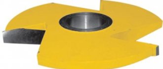
Disc cutters are designed for processing narrow surfaces, cutting grooves, trimming ledges, cutting off workpieces, etc. Disc cutters operate in difficult conditions of non-free (closed on several sides) cutting; The milling process is often accompanied by vibrations.
Rice. 4.28. Types of disk cutters: a – double-sided; b – three-sided; c – tripartite with multidirectional eubiae; g – grooved; - undercut angle
The following types of disk cutters are distinguished: double-sided, three-sided, slotted, slotted and cutting (Fig. 4.28). For double-sided disk cutters (Fig. 4.28, a) the teeth are located on the cylindrical and one end surfaces, and for three-sided disk cutters (Fig. 4.28, b) - on both ends. Accordingly, these cutters can process two or three mutually perpendicular surfaces in grooves and shoulders. The cutters are made with large teeth (for roughing) and fine teeth (for finishing). The former are characterized by the removal of large volumes of metal from deep grooves and recesses, so they have a large volume of chip flutes. The teeth of these cutters, with a small cutting edge width, are either straight or inclined to the axis. Angled teeth also provide more uniform milling, have favorable end tooth geometry and better chip removal. Three-sided cutters are made with multi-directional teeth, which makes it possible to create positive rake angles γ>0 on the end cutting edges (Fig. 4.28, c). When regrinding, the width of such a cutter decreases, so double cutters are also used, consisting of two halves, between which a measuring ring is placed. The geometric parameters of a three-sided disk cutter with equidirectional teeth are shown in Fig. 4.29.
Rice. 4.29. Three-sided disc cutter with equidirectional teeth
Solid cutters are made with a diameter d = 63...125 mm and a width B = 6...28 mm, and prefabricated cutters with insert knives with a diameter d = 75...200 mm and a width B = 12...60 mm. Such cutters are made of high-speed steel with fastening in wedge-shaped grooves using corrugations (Fig. 4.28, c). A disk cutter with insert knives is shown in Fig. 4.30.
Disc cutters equipped with mechanically fastened carbide inserts have become widespread in recent years. The designs of these cutters use methods for attaching plates structurally by analogy with face mills. However, additional difficulties arise here due to the need to place fastening elements in narrow cutter bodies. For three-sided cutters, it is also necessary to ensure reliable chip removal and positive rake angles at the end cutting edges.
Rice. 4.30. Three-sided disc cutter equipped with carbide inserts
Rice. 4.31. Disc cutters equipped with SMP: a – three-sided with “open” bases for inserts; b – three-sided with plates based in liners; c – with fastening of plates and liners with screws; d – with tangential fastening of plates; d – with special plates for cutting work (a diagram of plate removal is shown on the left)
In Fig. 4.31, a shows a variant of a disk cutter in which triangular plates 2 (without holes) are attached to the body 1 using wedges 3 and screws 4, as well as rings 1 and serve as one of the bases for the cutting plates. Another basis is open grooves in the cutter body with different directions of inclination to the axis of adjacent teeth, ensuring reliable chip removal and positive rake angles at the end cutting edges.
In Fig. 4.31, b shows a diagram of the fastening of triangular plates 2 in inserts 5 with wedges 3 and screws 4. The inserts 3 have V-shaped grooves for the plates and are located on the front surface of the plates 2. They are fastened in the body 1 with screws 6. For such cutters, the inserts are replaceable, the body is well protected from damage and normal chip removal is ensured, but they can be successfully used only at relatively small cutting depths.
In Fig. 4.31, c shows the option of fastening the plates with 2 screws with a conical head through a hole to the liner 3. The liner is fastened to the body with a wedge 4 and screw 5. The diagram for fastening the plates of disk cutters working with small depths and cutting widths is shown in Fig. 4.31, g. Specially designed plates with positive rake angles are attached directly to the body with screws on both sides. Replacement of plates in case of breakage or chipping is done using a special key (Fig. 4.31, d). The special shape of the front edge of the inserts ensures good chip crushing, the lowest cutting forces and high reliability of the cutters. In Fig. Figure 4.32 shows a three-sided disk cutter with mechanically fastened triangular inserts with clearance corners. The cutter is a body 1, in the grooves of which inserts with triangular cutting inserts 3 are placed. The cutting inserts 3 are attached to the inserts with screws 6, and the inserts themselves are attached to the body with mounting screws 4, 5. In disk cutters, much attention is paid to increasing the reliability of fastening the cutting inserts, their placement and regulation. In Fig. Figure 4.33 shows a diagram of a three-sided disk cutter with adjustable plates 2 (parallelogram type) located in body 1.
Rice. 4.32. Three-sided disc cutter with mechanically fastened triangular inserts with positive corners
Rice. 4.33. Diagram of a three-sided disk cutter with adjustable plates: 1 – body; 2 – cutting plates; 3 – adjusting pin and screw; 5 – fixing screw
By moving the adjusting pin 3 and the bevel, as well as the screws 4, the position of the plates is adjusted in the axial direction. Their position is fixed with screw 5.
Groove cutters (Fig. 4.34, d) are designed for milling grooves that are precise in width. Slotted cutters have a shorter cutting edge length with geometric parameters of the teeth γ=10...15о, α=20о. Auxiliary cutting edges at the ends are obtained by sharpening with an angle φ1=1...2о. Groove cutters are made with a diameter of 50...100 mm and a width of 3...16 mm.
Rice. 4.34. Slotting and cutting cutters: a – slotted (slotted) and solid cutting; b – cutting team (saw with insert knives); c – segmental; d - cutter diameter; φ1— undercut angle
Slotting and cutting cutters are similar in tooth shape to slotted ones and are used for cutting shallow and narrow grooves with a width of B = 0.2...6.0 mm, as well as for cutting workpieces of any profile and thickness. Solid cutters with a diameter of 20...315 mm are made with small, medium and large teeth, with angles γ=0...10o, α=20o, φ1=30/...1o (Fig. 4.34, a).
Prefabricated cutters with a diameter of 250...2000 mm are equipped with insert knives (Fig. 4.34, b) or segments made of high-speed steel. The segments consist of 4...8 teeth and are secured with rivets on the saw blade, which is made of ordinary structural steel (Fig. 4.34, c).
The operating conditions for slotting and cutting cutters are quite difficult, which is due to their small width and insufficient rigidity. To increase the durability of cutters, their teeth, which can be shaped without a ribbon (Fig. 4.35, a) and with a ribbon (Fig. 4.35, b), are sharpened without a ribbon. The angle of the face undercut ranges from 1030/ to 50. The angle of the face undercut φ1 ranges from 1o30/ to 5o.
Rice. 4.35. Cutting cutter tooth shapes; without ribbon (a); with ribbon(b)
Cutting cutters are manufactured with a fine tooth (type 1), with a medium tooth (type 2) and a large tooth (type 3). Type 3 allows you to create chip separation conditions and improve cutting conditions, especially when cutting large workpieces. By redistributing the cutting forces between the teeth, it is possible to increase the durability of cutters and machining performance. Segment cutters (saws) are a type of cutting cutters (Fig. 4.36). Segment cutters are designed for cutting large workpieces, therefore, when the workpiece diameter is more than 250 mm, it becomes advisable to manufacture them as prefabricated ones - from separate segments. In fact, segment cutters are more similar to saws (the back of the tooth is made along an arc, the rake angle γ is selected from 0 to 25o, the back angle α= 12...16o, tooth height h=0.5*S, where S is the pitch between the teeth). However, unlike a saw, segment cutters do not have teeth set.
Rice. 4.36. Diagram of a segmented cutting mill (saw) made of high-speed steel: a – appearance of the saw; b – segment; c – segment geometry
Purpose of the tool
Cutting cutters manufactured in accordance with GOST 2679-93 are intended for processing cast iron and steel blanks and parts. They perform parting, trimming, milling grooves and spline grooves on external surfaces. A disk cutter for metal is used in various operations:
- cutting pieces from rolled products;
- trimming casting allowances and profits on small parts;
- cutting grooves for fixing parts;
- milling of key and spline grooves.
The smooth round axles in the conveyor chain do not fall out of their bushings only due to the fact that a plate is inserted into a narrow slot made by a circular saw.
The grooves at the end of the castle nut have a variable cross-section. Their sides are formed by rays from the center of the radius. Therefore, they are cut out in 2 passes, first along the tangent of one side, then the second end of the crown sample is cut to size.
The splines are cut using rectangular teeth with high dimensional accuracy according to H6 and H7. The spline width and depth are normalized and the tool is manufactured to the appropriate size and configuration.
Characteristics and material
The characteristics and material from which the nozzle can be made are indicated in the state document GOST 2679-93. Characteristics of disc cutters for metal, prescribed in GOST:
- Diameter range - from 20 to 315 mm.
- Number of teeth - from 32 to 200.
- Width - from 0.2 to 3.5 mm.
- The maximum width deviation is up to 0.3 mm.
In the manufacture of cutters for metal, high-speed steel is most often used, but alloy and carbon steel can also be used.
The cutting parts are made of hard alloys with high wear resistance. Additionally, they can be coated with mineral ceramics, metal ceramics, or diamond coating. The shank must be made of ductile metal with high resistance to torsion and impact. The best steel options are St 40X, St 45, U10, U8.
Features of steel for the manufacture of cutters
The equipment is made of high-speed alloys, which include high-alloy steel grades with increased heat resistance. A similar distinctive feature is achieved by introducing molybdenum, chromium and vanadium into the alloy in combination with tungsten. For the production of cutting cutters, the following grades of steel are mainly used: R6M5, R12, R18.
Alloys are supplied to factories for the manufacture of cutting tools in the form of steel blanks (forgings).
When cutters are heated to harden, austenite begins to form in the alloy. It contains a relatively small amount of carbon and is heavily doped. The cutting tool receives a special structure after hardening and consists of martensite with small needles, various carbides and retained austenite.
The main alloying additives for high-speed steels are vanadium, tungsten, molybdenum and cobalt. It is these elements that can provide the required red resistance of the material. Chromium must be added to such alloys
Particular attention is paid to the amount of carbon in the steel: its number must be such that carbides of the introduced additives can form in the alloy. If the amount of carbon is less than 0.7%, then the finished cutter will not have the required hardness
How do alloying elements affect the properties of alloys:
- Phosphorus and sulfur have a negative impact on the characteristics of high-speed steel compositions. In the alloy, their amount should not exceed 0.03 and 0.015%, respectively.
- Tungsten and molybdenum are the main alloying additives. It is thanks to them that a high degree of operational and red-hardness of steel is ensured.
- The alloy should contain no more than 4% chromium. It imparts increased hardenability to the metal.
- Cobalt increases red resistance, but removes carbon from the steel and reduces its strength and toughness.
Most often, the tool is made of steel grade R6M5. Its cost is lower, but the cutter is also less wear-resistant than materials made from the P18 and P12 brands.
The P18 alloy has maximum wear resistance: it contains the largest amount of tungsten, hence the high cost. And in terms of heat resistance, the best tool is considered to be one made of P12 steel.
Features of choosing and working with a cutting mill
Here are the basic recommendations for the selection and use of metal cutting cutters:
- The cleanliness of the resulting cut and the speed depend on the number of teeth on the cutter. The more teeth, the cleaner the cut.
- Mills with a large number of teeth (80 or more) are recommended for finishing. When using this tool, chip removal is difficult and the load on the equipment increases. Therefore, for initial rough cutting, cutters with a small number of teeth (10-40 pieces) are recommended, after which additional cleaning of the end is necessary.
- A tool with a medium number of teeth (40-80 pcs.) is the most versatile and suitable for many operations.
- For working with metal workpieces with a strength of 500 to 800, cutters made of R6M5 steel are recommended due to the presence of molybdenum in the composition. For workpieces of greater hardness, it is advisable to use cutters containing cobalt.
- To work with stainless steel grades, cutters with tungsten carbide tips are used, which cannot be sharpened.
- During operation, the cutting speed must be set in accordance with the reference literature. For high-speed steels it is about 40-60 m/min.
- To obtain the cleanest possible end, it is recommended to work with low feeds.
Classification of cutters according to some characteristics
Of course, the above distinctions (by configuration, purpose) are not the only ways to distinguish between equipment. A real milling machine operator has such a large assortment of products that he will not be able to sort it out without difficulty. What other reasons are there for classification?
Different number of visits
The following are considered standard:
- • Single pass.
- • Two-way.
- • Four-lead.
But there can be any number of turns.
The fewer entries, the larger the allocated area for the grooves. The peculiarity of working with such a tool is that at each moment only one specific cutting edge affects the workpiece. This has a very positive effect on creating a product at high speeds and speeds, as it allows waste to be removed smoothly.
This is also relevant when carrying out activities with soft metals and other substances, for example, plastic or PVC, acrylic. They are also used for roughing and roughing procedures, when quality and accuracy are not the most important indicators.
Multi-pass ones are used when working with materials that have a hard and brittle structure. The movement will be smooth, without shocks, because several teeth touch the surface at the same time.
Chip removal type
Everything is simple here - the waste flies either upwards, which is the direction all milling operators are accustomed to handling, or downwards. The first option is most convenient if grooves or a blind hole are created, since metal does not accumulate there. But there is also a minus - part of everything “flying out” can land again on the working area and interfere with good cutting. The second option, accordingly, has narrower capabilities, but is more recommended for some types of work.
Three-sided disk cutter 100x16x32 Z=20 Р6М5
Three-sided disk cutter 100x16x32 Z=20 Р6М5
There are no items in the cart There are no items in the cart
+7(495)105-59-19
Russian Metal
RUMETT
»Tool
»
Cutting tools
»
Milling cutters
»
3-sided disc cutters
Three-sided disk cutter 100x16x32 Z=20 P6M5 type 1 (straight teeth) is produced in accordance with GOST 28527-90, it is intended for processing general-purpose grooves and keyways. Cutter diameter (D) 100 mm, cutter width (L) 16 mm (tolerance range k11 - general purpose cutter), bore diameter 32 mm. Made of high-speed steel R6M5 and designed for processing structural steel and cast iron. An example of marking is cutter 2240-0214 R6M5 GOST 28527-90. |
Properties and characteristics
| Cutter diameter (D), mm | 100 |
| Number of teeth, Z | 20 |
| Width (L), mm | 16 |
| d, bore diameter (mm) | 32 |
| Processed material | structural steel and cast iron |
| Number according to GOST | 2240-0214 |
| Type | type 1 (straight teeth) |
| Material | Р6М5 (HSS) |
| GOST | 28527-90 |
Related products and discounts
Advertisements Search for a reliable supplier of rolled metal Valid until February 28, 2021 We will buy sheet paronite of any size, thickness 1.5 - 2 and 3 mm Valid until December 31, 2021
RUMETT
We invite partners to place goods and services
- Special sections
- Hot links
- Services
- For reference
Regions of supply of goods: Russia, Kazakhstan, Belarus, Moldova, European Union countries. Installation work only on the territory of the Russian Federation. All information presented on the site regarding technical characteristics, warehouse availability, cost of goods is for informational purposes only and under no circumstances constitutes a public offer as defined by the provisions of Article 437(2) of the Civil Code of the Russian Federation. The final prices and conditions are indicated by the manager in the issued invoice-delivery agreement in accordance with Art. 506 of the Civil Code of the Russian Federation.
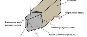
Design Features
For work on a milling machine, they mainly use cutting and slotting disc cutters for metal GOST 2679-93. They are a thin disk with teeth along the edge - the outer diameter. They are made from high-alloy steels of the tool group. Main elements of the cutter:
- hub with mounting hole;
- disk;
- teeth
The thickness of the hub is the same as the disk or greater than it within 0.2 mm. It has a mounting hole with or without a slot. The tool is mounted on a mandrel mounted on the machine spindle. Fixed with a washer and nut. For circular saws with a diameter of more than 200 mm, driver holes are provided as standard. They are drilled on the bushing in the amount of 4 pieces.
According to their purpose, disc cutters are divided into 2 classes:
- cutting - for performing cutting and slotting work;
- slotted - cutting, cutting grooves.
The profile of the chip flutes depends on the type of disk cutter and the number of teeth. The angle is maintained at 60 degrees, the depth of the groove and the sharpening angle change. On a medium and small tooth, a backing is made at an angle of up to 20 degrees relative to the tangent line of the outer diameter of the disc. The smaller the tooth, the less the tool feed, since the chips should flow out of the groove and not clog the grooves.
On type 3 cutters – with large teeth – the side surfaces of the cutting edge are sharpened. Combined with a deep groove profile, this allows for fast cutting with high feed rates.
When the circular saw operates, coolant is supplied to the cutting area. It promotes the flow of chips and prevents overheating that occurs when cutting metal with a cutter and friction of metal surfaces.
Slotted
Keyways and grooves have a specific configuration and require high precision and cleanliness of processing. For a slotted disk cutter, these parameters are ensured by the shape of the tooth and sharpening along three surfaces. The cutting edge on the sides forms a right angle.
The mounting hole has a keyway, which allows cutting with greater force, avoiding turning the tool on the mandrel.
Teeth are set - the plates are inserted into grooves in the body of the cutter and soldered. On large-diameter tools, fastening with wedges is possible. Assembly is carried out on a special tool plate, which ensures greater accuracy along the plane of the outer cutting edges. After a set of plates and their fastening, the disk cutter is checked for axial and radial runout. To do this, it is put on a mandrel and rotated. The indicator head is alternately brought to the end and radius.
https://www.youtube.com/watch?v=h8uMSH_RsBU
Design and Application
They are used for cutting parts of workpieces and cutting grooves. They are circles with external cutting teeth. According to GOST 2679-93 (ISO 2296-72), its diameter can vary between 20-315 mm, and thickness - 0.2-6 mm. However, larger sizes are also found in production, up to 620 mm.
The saw is selected based on the type of material and requirements for cleanliness of the cut. Based on this, the number of teeth and type are determined. With medium and small quantities they are optimal for cutting steel and cast iron.
What types of cutters are there for metal?
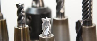
A metal cutter is a special tool used to cut metal workpieces. This is done through translational and rotational movements. This type has a large number of varieties, due to which the range of operations performed with its help is very large.
Today we will tell you the operating principle of such a tool and find out what types of metal cutters exist.
The cutter itself is the initial part of the movement, and when processing the workpiece it comes into contact with its surface. This tool is characterized by a large number of types of working surface.
Due to the fact that there are different types of metal cutters, material can be sampled even in the most difficult areas
But at the same time, it is extremely important to choose one or another type of tool, as well as the method of feeding it. It can be translational-rotational, screw, etc.
d.
Cutting edges are made from materials such as:
- some types of steel;
- hard alloys;
- diamonds;
- ceramics;
- card wire, etc.
Next, we will look at the key types of cutters designed for processing metal workpieces and their characteristic features.
Classification
Metal cutters differ from each other in the following ways:
- on the placement of its cutting parts (or teeth);
- by type of sharpening;
- in direction (helical, inclined or others);
- by design (composite, monolithic or prefabricated);
- by material;
- for fastening cutting tools.
There are more types, taking into account different features, but listing them all without exception would take quite a long time.
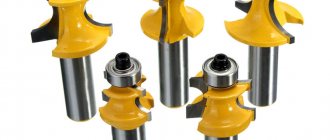
Varieties and applications
Each type of cutter is used only at a certain technological stage of material processing. It all depends on what the task is.
For example, cylindrical ones come in two types:
- screw;
- with straight teeth.
The latter type is used for more primitive tasks and mainly in narrow, limited areas. But cutters with cutting screw parts have a more universal purpose.
But since axial forces can be significant, the use of such a tool is limited by the angle of inclination of the cutting edge, and this is no more than 450. It is in such cases that it is necessary to install cylindrical dual tools. This design is characterized by the fact that during the processing of materials, the cutting parts cover the junction of the halves.
Other types of instruments
Hobs have a specific field of application. In this case, the material is processed using the rolling method. The selection of workpieces is carried out in the process of point contact with them with a cutter. Depending on the direction of their screws, they are right-handed or left-handed, they can also be single- or multi-start, solid or assembled, have ground or unground teeth.
End products are used to process ledges, grooves and more. Their tails can be cylindrical or conical. They are also intended for pre-processing of materials (with large teeth) or finishing, with fine teeth. They can be equipped with soldered cutting inserts or be monolithic.
End grinding tools are used for machining forged or cast alloys. And with the help of key products, T-profiles are selected. They have two teeth, one at the end and the second in the middle. The parameters of the workpiece sampling zone are determined by the interval between them.
Another type of similar tool is a cutting tool. With their help, metal blanks are completely or partially trimmed. The cutting edges are located only on the upper edges of the teeth, but they are not on the edges.
Depending on the size of the teeth, cutting cutters are:
- large;
- average;
- small.
In this case, small and medium ones are used for cutting steel and cast iron, and large ones are used for processing light magnesium, aluminum and other alloys.
To process metal products, craftsmen most often use a milling cutter. Moreover, it can be simultaneously equipped with several types of teeth, cutting edges or blades. This tool can have different profiles, shapes, types, sizes and applications. We have already discussed some types of metal cutters and the features of their use and operation above.
How to choose the right cutter for metal
In order to obtain metal structures of the correct shape, in compliance with the parameters specified in the project, all its elements are pre-processed. There are several methods for this, the most popular of which is milling. The accuracy of the work performed directly depends on the correctly selected cutter - the cutting material itself.
Disc cutters for metal
Cutting cutter
Cutting and slotting cutters are used for cutting workpieces, processing grooves, ledges, flat surfaces, and cutting splines.
Disc cutting and slotting cutters GOST 2679-93
Types of cut-off cutters:
1 — cutters with small teeth;
2 — cutters with a medium tooth;
3 - cutters with large teeth
class 1 - for cutting splines
class 2 - for slotting and cutting work
| Designation of cutters type | D | B | d | Number of teeth for cutters type | ||||
| 1 | 2 | 3 | 1 | 2 | 3 | |||
| 2254-0642 | — | — | Cutting cutter d 20 | 0,2 | 5 | 80 | — | — |
| 2254-0644 | — | — | 0,25 | 5 | 64 | |||
| 2254-0646 | — | — | 0,3 | 5 | 64 | |||
| 2254-0648 | — | — | 0,4 | 5 | 64 | |||
| 2254-0652 | — | — | 0,5 | 5 | 48 | |||
| 2254-0654 | — | — | 0,6 | 5 | 48 | |||
| 2254-0656 | — | — | 0,8 | 5 | 48 | |||
| 2254-0658 | — | — | 1 | 5 | 40 | |||
| 2254-0662 | — | — | 1,2 | 5 | 40 | |||
| 2254-0664 | — | — | 1,40* | 5 | 40 | |||
| 2254-0666 | — | — | 1,6 | 5 | 40 | |||
| 2254-0668 | — | — | 2 | 5 | 32 | |||
| 2254-0672 | — | — | 2,5 | 5 | 32 | |||
| 2254-0674 | — | — | Cutting cutter d 25 | 0,2 | 8 | 80 | ||
| 2254-0676 | — | — | 0,25 | 8 | 80 | |||
| 2254-0678 | — | — | 0,3 | 8 | 80 | |||
| 2254-0682 | — | — | 0,4 | 8 | 64 | |||
| 2254-0684 | — | — | 0,5 | 8 | 64 | |||
| 2254-0686 | — | — | 0,6 | 8 | 64 | |||
| 2254-0688 | — | — | 0,8 | 8 | 48 | |||
| 2254-0692 | — | — | 1 | 8 | 48 | |||
| 2254-0694 | — | — | 1,2 | 8 | 48 | |||
| 2254-0696 | — | — | 1,40* | 8 | 48 | |||
| 2254-0698 | — | — | 1,6 | 8 | 40 | |||
| 2254-0702 | — | — | 2 | 8 | 40 | |||
| 2254-0704 | — | — | 2,5 | 8 | 40 | |||
| 2254-0706 | — | — | 2,80* | 8 | 40 | |||
| 2254-0708 | — | — | 3,00* | 8 | 32 | |||
| 2254-0712 | — | — | Cutting cutter d 32 | 0,2 | 8 | 100 | ||
| 2254-0714 | — | — | 0,25 | 8 | 100 | |||
| 2254-0716 | 2254-2002 | — | 0,3 | 8 | 80 | 40 | ||
| 2254-0718 | 2254-2004 | — | 0,4 | 8 | 80 | 40 | ||
| 2254-0722 | 2254-2006 | — | 0,5 | 8 | 80 | 40 | ||
| 2254-0724 | 2254-2008 | — | 0,6 | 8 | 64 | 32 | ||
| 2254-0726 | 2254-2011 | — | 0,8 | 8 | 64 | 32 | ||
| 2254-0728 | 2254-2013 | — | 1 | 8 | 64 | 32 | ||
| 2254-0732 | 2254-2015 | — | 1,2 | 8 | 48 | 24 | ||
| 2254-0734 | — | — | 1,40* | 8 | 48 | — | ||
| 2254-0736 | 2254-2017 | — | 1,6 | 8 | 48 | 24 | ||
| 2254-0738 | 2254-2019 | — | 2 | 8 | 48 | 24 | ||
| 2254-0742 | 2254-2022 | — | 2,5 | 8 | 40 | 20 | ||
| 2254-0744 | — | — | 2,80* | 8 | 40 | — | ||
| 2254-0746 | 2254-2024 | — | 3 | 8 | 40 | 20 | ||
| 2254-0748 | — | — | 4,00* | 8 | 40 | — | ||
| 2254-0752 | — | — | Cutting cutter d 40 | 0,2 | 10 | 128 | ||
| 2254-0754 | — | — | 0,25 | 10 | 100 | |||
| 2254-0756 | 2254-2026 | — | 0,3 | 10 | 100 | 48 | ||
| 2254-0758 | 2254-2028 | — | 0,4 | 10 | 100 | 48 | ||
| 2254-0762 | 2254-2031 | — | 0,5 | 10 | 80 | 40 | ||
| 2254-0764 | 2254-2033 | — | 0,6 | 10 | 80 | 40 | ||
| 2254-0766 | 2254-2035 | — | 0,8 | 10 | 80 | 40 | ||
| 2254-0768 | 2254-2037 | — | 1 | 10 | 64 | 32 | ||
| 2254-0772 | 2254-2039 | — | 1,2 | 10 | 64 | 32 | ||
| 2254-0774 | — | — | 1,40* | 10 | 64 | — | ||
| 2254-0776 | 2254-2042 | — | 1,6 | 10 | 64 | 32 | ||
| 2254-0778 | 2254-2044 | — | 2 | 10 | 48 | 24 | ||
| 2254-0782 | 2254-2046 | — | 2,5 | 10 | 48 | 24 | ||
| 2254-0784 | — | — | 2,80* | 10 | 48 | — | ||
| 2254-0786 | 2254-2048 | — | 3 | 10 | 48 | 24 | ||
| 2254-0788 | 2254-2051 | — | 4 | 10 | 40 | 20 | ||
| 2254-0792 | — | — | 5,00* | 10 | 40 | — | ||
| 2254-0796 | — | — | Cutting cutter d 50 | 0,25 | 13 | 128 | — | |
| 2254-0798 | 2254-2106 | — | 0,3 | 13 | 128 | 64 | ||
| 2254-0802 | 2254-2108 | — | 0,4 | 13 | 100 | 48 | ||
| 2254-0804 | 2254-1142 | — | 0,5 | 13 | 100 | 48 | ||
| 2254-0806 | 2254-1144 | — | 0,6 | 13 | 100 | 48 | ||
| 2254-0808 | 2254-1146 | — | 0,8 | 13 | 80 | 40 | ||
| 2254-0812 | 2254-1148 | 2254-1422 | 1 | 13 | 80 | 40 | 20 | |
| 2254-0814 | 2254-1152 | 2254-1424 | 1,2 | 13 | 80 | 40 | 20 | |
| 2254-0816 | 2254-1154 | 2254-1426 | 1,40* | 13 | 80 | 40 | — | |
| 2254-0818 | 2254-1156 | 2254-1426 | 1,6 | 13 | 64 | 32 | 16 | |
| 2254-0822 | 2254-1158 | 2254-1428 | 2 | 13 | 64 | 32 | 16 | |
| 2254-0824 | 2254-1162 | 2254-1432 | 2,5 | 13 | 64 | 32 | 16 | |
| 2254-0826 | 2254-1164 | — | 2,80* | 13 | 64 | 32 | — | |
| 2254-0828 | 2254-1166 | — | 3 | 13 | 48 | 24 | ||
| 2254-0832 | 2254-2053 | — | 4 | 13 | 48 | 24 | ||
| 2254-0834 | 2254-2055 | — | 5 | 13 | 48 | 24 | ||
| 2254-0836 | — | — | 6,00* | 13 | 40 | — | ||
| 2254-0842 | — | — | Cutting cutter d 63 | 0,3 | 16 | 128 | ||
| 2254-0844 | — | — | 0,4 | 16 | 128 | |||
| 2254-0846 | 2254-1168 | — | 0,5 | 16 | 128 | 64 | ||
| 2254-0848 | 2254-1172 | — | 0,6 | 16 | 100 | 48 | ||
| 2254-0852 | 2254-1174 | — | 0,8 | 16 | 100 | 48 | ||
| 2254-0854 | 2254-1176 | 2254-1434 | 1 | 16 | 100 | 48 | 24 | |
| 2254-0856 | 2254-1178 | 2254-1436 | 1,2 | 16 | 80 | 40 | 20 | |
| 2254-0858 | 2254-1182 | — | 1,4* | 16 | 80 | 40 | — | |
| 2254-0862 | 2254-1184 | 2254-1438 | 1,6 | 16 | 80 | 40 | 20 | |
| 2254-0864 | 2254-1186 | 2254-1442 | 2 | 16 | 80 | 40 | 20 | |
| 2254-0866 | 2254-1188 | 2254-1444 | 2,5 | 16 | 64 | 32 | 16 | |
| 2254-0868 | 2254-1192 | — | 2,8* | 16 | 64 | 32 | — | |
| 2254-0872 | 2254-1194 | 2254-1446 | 3 | 16 | 64 | 32 | 16 | |
| 2254-0874 | 2254-2057 | — | 4 | 16 | 64 | 32 | — | |
| 2254-0876 | 2254-2059 | — | 5 | 16 | 48 | 24 | ||
| 2254-0878 | 2254-2062 | — | 6 | 16 | 48 | 24 | ||
| 2254-0886 | — | — | Cutting cutter d 80 | 0,5 | 22 | 128 | — | |
| 2254-0888 | 2254-1196 | — | 0,6 | 22 | 128 | 64 | ||
| 2254-0892 | 2254-1198 | — | 0,8 | 22 | 128 | 64 | ||
| 2254-0894 | 2254-1202 | 2254-1448 | 1 | 22 | 100 | 48 | 24 | |
| 2254-0896 | 2254-1204 | 2254-1452 | 1,2 | 22 | 100 | 48 | 24 | |
| 2254-0898 | 2254-1206 | — | 1,4* | 22 | 100 | 48 | — | |
| 2254-0902 | 2254-1208 | 2254-1454 | 1,6 | 22 | 100 | 48 | 24 | |
| 2254-0904 | 2254-1212 | 2254-1456 | 2 | 22 | 80 | 40 | 20 | |
| 2254-0906 | 2254-1214 | 2254-1458 | 2,5 | 22 | 80 | 40 | 20 | |
| 2254-0908 | 2254-1216 | — | 2,8* | 22 | 80 | 40 | — | |
| 2254-0912 | 2254-1218 | 2254-1462 | 3 | 22 | 80 | 40 | 20 | |
| — | 2254-1222 | — | 3,5* | 22 | — | 40 | — | |
| 2254-0914 | 2254-1224 | — | 4 | 22 | 64 | 32 | — | |
| 2254-0916 | 2254-2064 | — | 5 | 22 | 64 | 32 | ||
| 2254-0918 | 2254-2066 | — | 6 | 22 | 64 | 32 | ||
| 2254-0922 | 2254-2112 | — | Cutting cutter d 100 | 0,5* | 22 | 160 | 64 | |
| 2254-0924 | 2254-1226 | — | 0,6 | 22 | 160 | 64 | ||
| 2254-0926 | 2254-1228 | — | 0,8 | 22 | 128 | 64 | ||
| 2254-0928 | 2254-1232 | 2254-1464 | 1 | 22 | 128 | 64 | 32 | |
| 2254-0932 | 2254-1234 | 2254-1466 | 1,2 | 22 | 128 | 64 | 32 | |
| 2254-0934 | 2254-1236 | — | 1,4* | 22 | 100 | 64 | — | |
| 2254-0936 | 2254-1238 | 2254-1468 | 1,6 | 22 | 100 | 48 | 24 | |
| 2254-0938 | 2254-1242 | 2254-1472 | 2 | 22 | 100 | 48 | 24 | |
| 2254-0942 | 2254-1244 | 2254-1474 | 2,5 | 22 | 100 | 48 | 24 | |
| 2254-0944 | 2254-1246 | — | 2,8* | 22 | 100 | 48 | — | |
| 2254-0946 | 2254-1248 | 2254-1476 | 3 | 22 | 80 | 40 | 20 | |
| — | 2254-1252 | — | 3,5* | 22 | — | 40 | — | |
| 2254-0948 | 2254-1254 | — | 4 | 22 | 80 | 40 | ||
| 2254-0952 | 2254-2068 | — | 5 | 22 | 80 | 40 | ||
| 2254-0954 | 2254-2071 | — | 6 | 22 | 64 | 32 | ||
| 2254-0958 | — | — | Cutting cutter d 125 | 0,8 | 22 | 160 | — | |
| 2254-0962 | 2254-1258 | — | 1 | 22 | 160 | 80 | ||
| 2254-0964 | 2254-1262 | — | 1,2 | 22 | 128 | 64 | ||
| 2254-0966 | 2254-1264 | — | 1,4* | 22 | 128 | 64 | ||
| 2254-0968 | 2254-1266 | 2254-1478 | 1,6 | 22 | 128 | 64 | 32 | |
| 2254-0972 | 2254-1268 | 2254-1482 | 2 | 22 | 128 | 64 | 32 | |
| 2254-0974 | 2254-1272 | 2254-1484 | 2,5 | 22 | 100 | 48 | 24 | |
| 2254-0976 | 2254-1274 | — | 2,8* | 22 | 100 | 48 | — | |
| 2254-0978 | 2254-1276 | 2254-1486 | 3 | 22 | 100 | 48 | 24 | |
| — | 2254-1278 | 2254-1488 | 3,5* | 22 | — | 48 | 24 | |
| 2254-0982 | 2254-1282 | 2254-1492 | 4 | 22 | 100 | 48 | 24 | |
| 2254-0984 | 2254-2073 | — | 5 | 22 | 80 | 40 | — | |
| 2254-0986 | 2254-2075 | — | 6 | 22 | 80 | 40 | ||
| 2254-0992 | 2254-1286 | — | Cutting cutter d 160 | 1,2 | 32 | 160 | 80 | |
| 2254-0994 | 2254-1288 | — | 1,4* | 32 | 160 | 80 | ||
| 2254-0996 | 2254-1292 | 2254-1494 | 1,6 | 32 | 160 | 80 | 40 | |
| 2254-0998 | 2254-1294 | 2254-1496 | 2 | 32 | 128 | 64 | 32 | |
| — | — | 2254-1642 | 2 | 32 | — | — | 22 | |
| 2254-1002 | 2254-1296 | 2254-1498 | 2,5 | 32 | 128 | 64 | 32 | |
| 2254-1004 | 2254-1298 | — | 2,8* | 32 | 128 | 64 | — | |
| 2254-1006 | 2254-1302 | 2254-1502 | 3 | 32 | 128 | 64 | 32 | |
| — | 2254-1304 | 2254-1504 | 3,5 | 32 | — | 64 | 32 | |
| 2254-1008 | 2254-1306 | 2254-1506 | 4 | 32 | 100 | 48 | 24 | |
| — | 2254-1308 | 2254-1508 | 4,5 | 32 | — | 48 | 24 | |
| 2254-1012 | 2254-1312 | — | 5 | 32 | 100 | 48 | — | |
| — | 2254-1732 | — | 5,5 | 32 | — | 48 | ||
| 2254-1014 | 2254-1314 | — | 6 | 32 | 100 | 48 | ||
| 2254-1024 | 2254-1322 | — | Cutting cutter d 200 | 1,6 | 32 | 160 | 80 | — |
| 2254-1026 | 2254-1324 | 2254-1512 | 2 | 32 | 160 | 80 | 40 | |
| 2254-1028 | 2254-1326 | 2254-1514 | 2,5 | 32 | 160 | 80 | 40 | |
| 2254-1032 | 2254-1328 | — | 2,8* | 32 | 160 | 80 | — | |
| 2254-1034 | 2254-1332 | 2254-1516 | 3 | 32 | 128 | 64 | 32 | |
| — | 2254-1334 | 2254-1518 | 3,5* | 32 | — | 64 | 32 | |
| 2254-1036 | 2254-1336 | 2254-1522 | 4 | 32 | 128 | 64 | 32 | |
| — | 2254-1338 | 2254-1524 | 4,5* | 32 | — | 64 | 32 | |
| 2254-1038 | 2254-1342 | 2254-1526 | 5 | 32 | 128 | 64 | 32 | |
| — | 2254-1734 | — | 5,5* | 32 | — | 64 | — | |
| 2254-1042 | 2254-1344 | — | 6 | 32 | 100 | 48 | ||
| 2254-1046 | 2254-1348 | — | Cutting cutter d 250 | 2 | 32 | 200 | 100 | — |
| 2254-1048 | 2254-1352 | 2254-1528 | 2,5 | 32 | 160 | 80 | 40 | |
| 2254-1052 | 2254-1354 | — | 2,8* | 32 | 160 | 80 | — | |
| 2254-1054 | 2254-1356 | 2254-1532 | 3 | 32 | 160 | 80 | 40 | |
| — | 2254-1358 | 2254-1534 | 3,5* | 32 | — | 80 | 40 | |
| 2254-1056 | 2254-1362 | 2254-1536 | 4 | 32 | 160 | 80 | 40 | |
| — | 2254-1364 | 2254-1538 | 4,5* | 32 | — | 80 | 40 | |
| 2254-1058 | 2254-1366 | 2254-1542 | 5 | 32 | 128 | 64 | 32 | |
| — | 2254-1736 | 2254-1742 | 5,5* | 32 | — | 64 | 32 | |
| 2254-1062 | 2254-1368 | 2254-1544 | 6 | 32 | 128 | 64 | 32 | |
| 2254-1064 | 2254-1372 | 2254-1546 | Cutting cutter d 315 | 2,5 | 40 | 200 | 100 | 48 |
| 2254-1066 | 2254-1374 | — | 2,8* | 40 | 200 | 100 | — | |
| 2254-1068 | 2254-1376 | 2254-1548 | 3 | 40 | 200 | 100 | 48 | |
| — | 2254-1378 | — | 3,5* | 40 | — | 100 | — | |
| 2254-1072 | 2254-1382 | 2254-1552 | 4 | 40 | 160 | 80 | 40 | |
| — | 2254-1384 | — | 4,5* | 40 | — | 80 | — | |
| 2254-1074 | 2254-1386 | 2254-1554 | 5 | 40 | 160 | 80 | 40 | |
| — | 2254-1738 | 2254-1744 | 5,5* | 40 | — | 80 | 40 | |
| 2254-1076 | 2254-1388 | 2254-1556 | 6 | 40 | 160 | 80 | 40 | |
Fine tooth cutters.
A characteristic feature of this type of cutter is the large number of teeth. The front and rear surfaces of the teeth are formed by a groove with an angle of 60°, and the cavity is made with a small radius for the entire range of cutters. With this design, the teeth have a non-optimal clearance angle exceeding 60°, which reduces the strength of the cutting part. Therefore, fine-tooth cutters are designed to work with a milling depth not exceeding the width of the cutter, i.e. for milling small grooves and splines or for cutting thin sheet materials. An increase in cutting depth is also hampered by the small volume of grooves for accommodating chips.
Middle tooth cutters.
The number of teeth of these cutters is approximately two times less than that of type 1 cutters, and therefore the cutters have a more capacious chip flute. The standard provides two tooth profile shapes. The first shape is the same as that of fine-tooth cutters, the second has a strip along the rear surface with a clearance angle a = 20°. The width of the tape for cutters with a diameter of 50 mm is 0.5-0.9 mm and increases with increasing cutter diameter. Mills with a second tooth shape, due to the hardening of the cutting part, allow working with greater depth and feed than with the first.
Large tooth cutters. They have a number of teeth approximately 2 times less than type 2 cutters, which allows them to be used for cutting deep grooves in parts made of viscous materials, stainless and heat-resistant steels and alloys. A feature of the shape of the tooth and cavity of the cutters is the increased cavity radius and the volume of the chip flute.
For cutters with medium and large teeth, there are two forms of sharpening transitional cutting edges: form 1 and form 2. Form 1 teeth are made with two transitional cutting edges.
form 1
This sharpening of the teeth increases processing productivity by 2-2.5 times compared to conventional sharpening, makes it possible to mill deeper grooves, and eliminates breakage of cutters due to stacking of chips.
form 2
Sharpening teeth of form 2, compared to conventional sharpening, slightly increases durability by providing better heat dissipation from corner points, but does not improve the process of chip formation and removal
In cutters with small teeth and cutters with medium and large teeth with a width of B<1.6 mm, the teeth do not have transitional cutting edges. Their main cutting edge has a length equal to the width of the cutter.
Similar products: End mill for metal GOST 26595-85 Keyed mill for metal GOST 9140-78 Angle mill Three-sided disk mill GOST 28527-90
Classification of cutters according to some characteristics
Of course, the above distinctions (by configuration, purpose) are not the only ways to distinguish between equipment. A real milling machine operator has such a large assortment of products that he will not be able to sort it out without difficulty. What other reasons are there for classification?
Different number of visits
The following are considered standard:
- • Single pass.
- • Two-way.
- • Four-lead.
But there can be any number of turns.
The fewer entries, the larger the allocated area for the grooves. The peculiarity of working with such a tool is that at each moment only one specific cutting edge affects the workpiece. This has a very positive effect on creating a product at high speeds and speeds, as it allows waste to be removed smoothly.
This is also relevant when carrying out activities with soft metals and other substances, for example, plastic or PVC, acrylic. They are also used for roughing and roughing procedures, when quality and accuracy are not the most important indicators.
Multi-pass ones are used when working with materials that have a hard and brittle structure. The movement will be smooth, without shocks, because several teeth touch the surface at the same time.
Chip removal type
Everything is simple here - the waste flies either upwards, which is the direction all milling operators are accustomed to handling, or downwards. The first option is most convenient if grooves or a blind hole are created, since metal does not accumulate there. But there is also a minus - part of everything “flying out” can land again on the working area and interfere with good cutting. The second option, accordingly, has narrower capabilities, but is more recommended for some types of work.