To use the device, you need to know how and in what sequence to put the 2t30 theodolite device into operation, how to check and adjust it. It is necessary to be able to recognize the parts of the device and its operating principle to measure angles both horizontally and vertically.
General diagram of the main parts and axes of the theodolite.
Applicable:
- for topographic surveys;
- tacheometric works, survey processes;
- surveying measurements;
- on construction sites during marking work that does not require perfect accuracy.
Device characteristics
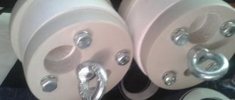
Tripod and optical plummet - used to install the theodolite above a point fixed on the ground.
Angular measurements are needed to determine the position of objects in space. Such manipulations are performed for a triangulation network. A classic type of work is geodetic measurements for the construction of all kinds of structures.
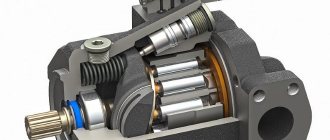
The accuracy of the device, close to ideal, is expressed in minutes, fractions of seconds. The theodolite has an optical and mechanical device for measuring angles, distances, and magnetic azimuths. The devices are divided into types depending on accuracy, including technical 2t30. The digital indices in the name indicate accuracy, that is, the square error in determining the angle in one step in seconds. Theodolite 2t30 device consists of components:
- ratchet, diopter ring, cap with adjustable screws of the thread network;
- sight with optics, vertical ring, pipe spacer;
- screws for adjusting, securing the dial, alidade, pipe, lifting, adjusting the dial;
- cylinder shape level, case base, pipe, stand;
- elements, mirror surfaces.
The reference compass is necessary for measuring magnetic azimuths and is installed in a groove located on the side cover of the vertical circle of the theodolite.
It is equipped with a micrometer, which increases the accuracy of measurements. With the help of its elements, geometric leveling is done, the plummet allows you to carry out work in a three-stand system. The distance can be calculated using a leveling rod.
The level-cylinder moves the horizontal dial perpendicular to the line in a vertical state. It is a glass tube like an ampoule, its cut is an arc with a radius of 3.5 to 200 m. This container is filled, as a rule, with alcohol, ether, that is, easily mobile properties. It is sealed while heated. As it cools, a bubble is created. The point in the center of the ampoule scale is taken as zero.
Devices of this nature have levels in the shape of a cylinder or circle; they differ in division parameters, sensitivity, and design.
The cylinder of the ampoule is framed in metal, it has an adjustment screw, there are divisions on the outside of the tube with a distance of 2 mm, and the point in the center is the zero point. Its axis is a line tangent to the level inside, at the zero point.
Field of view of the reference microscope.
Round - a glass ampoule, polished inside, with a certain roundness. Here the zero point is the center in the circle. The axis is the normal, laid through the zero, it is perpendicular.
The zero position is made smoother by contact levels. They consist of a level cylinder, above which there is a device with optics that transmits the edges of the ends of the bubble to the lens. It is placed at zero when its opposite faces overlap.
The level price is the angular indicator of the displacement of the bubble in one stroke. It can be in cylindrical 5-60, in round - 5-20.
Sensitivity is the smallest noticeable bubble movement, usually 0.1 stroke or 0.2 mm. Pipe elements - screws, optical parts, dimensional grid. It houses the sighting and optical axes. The first connects the lens to the threads with a dimensional network. The second eyepiece is connected to the lens.
Theodolite device 2T30M
Download from Depositfiles
Practical study of the geodesy course by students of specialty 0902 is carried out during laboratory classes. These classes cover the following main sections:
- theodolite, its structure and verification, methods for measuring angles;
- desk processing of theodolite survey results;
- level, its design and verification, methods of geometric leveling;
- desk processing of leveling results, profile drawing, route design.
1. THEODOLITE DEVICE
Theodolite is one of the main surveying instruments used in surveying terrain. It is designed to measure horizontal and vertical angles, distances (using a filament rangefinder) on the ground and determine the magnetic azimuths of lines. In this case, the theodolite calculates distances using a thread range finder and a leveling rod, and magnetic azimuths are determined using a reference compass included in the theodolite kit.
The purpose of the work is to study the basic elements of the theodolite design, their purpose, as well as master the technique of taking readings along the horizontal and vertical circles of the theodolite.
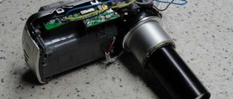
In Fig. Figure 1 shows a general view of the 2T30M theodolite, which is a repeating-type goniometric device, optical, i.e. has glass limbs of horizontal and vertical circles and reading systems that transmit images of divisions of the limbs into the field of view of the reading microscope located next to the telescope.
Spotting scope 4 has internal focusing and has 18x magnification. Sharp visibility of the grid of threads is achieved by rotating the diopter ring 7, and positioning the tube on the object (focusing) to obtain a clear image of the observed object (sighting target) is carried out by rotating the focused ring 8.
The grid consists of overlaps; its vertical stroke in one half of the field of view is made double. Two short horizontal reticle lines form a filament rangefinder. On the grid there is a scale with a division value of 1′. It is designed to measure small angles, such as fluctuations in a plumb line.
On both sides of the tube there are optical sights 5 for close aiming at the target. Theodolite stand 11 is removable, has a standard hole with a diameter of 34 mm, clamping screw 13 fastens the stand to the top part of the theodolite.
Rice. 1
In Fig. 1 shows the illumination mirror 14, but does not show the repeater device, the latter consisting of a lever located horizontally and a latch located vertically.
When the lever is pressed, the horizontal circle is fastened to the alidade and rotates with it; by pressing the latch, the horizontal circle is released and remains motionless when the alidade rotates.
Before work, the theodolite is installed on a tripod and centered over a point. After this, by rotating the lifting screws 12, the bubble of the cylindrical level 10 is brought to the middle in two mutually perpendicular planes.
Rotation of the theodolite in azimuth and precise pointing of the telescope at the object in the horizontal plane are carried out by rotating the aiming screw of the horizontal circle 2 with screw 1 secured with a clamp. Accurate pointing of the telescope at the observed object in the vertical plane is carried out by the aiming screw 3, while the clamp screw 9 must be secured .
During transportation, the theodolite is placed in a box (case).
The 2T30M theodolite reading device is a scale microscope. The eyepiece of the microscope 6 is located next to the eyepiece of the telescope. In the field of view of such a microscope (Fig. 2), images of a limb and a scale are visible, the length of which is equal to the image of one degree division. The index for counting is the stroke of the dial located within the scale. So, in the example shown in Fig. 2, the reading along the vertical circle is 1°08′, and along the horizontal circle – 175°47′.
Fig.2
Download from Depositfiles
Working Condition: Features
The tube must be adjusted by eye, that is, rotate the eyepiece until the threads become clear. The ratchet is adjusted until the target is clear. The horizontal position is adjusted with a screw for aiming, first the alidade is secured, the vertical position is adjusted with a screw, then secured with another screw.
Diagram of the main axes of the theodolite.
The field of view is the area viewed by the pipe when stationary. The strokes and numbers fall into the field of view of the microscope; it is fixed by eye with a diopter ring until it is illuminated.
The horizontal circle is a dial; there are degrees on it behind the clock hand. The circles have gradations of 1°. There is 359° in horizontal, vertical has 0-75° and from 0 to - 75°.
The alidade serves as a reference detail; it is coaxial to the plane with the gradation. A vertical circle is the same as a horizontal circle, it measures oblique angles.
The cylinder-level bubble is adjusted with bolts.
Theodolite 2T30 and 2T30P
Theodolite 2T30 is a second-generation optical device developed by the Ural Optical-Mechanical Plant. It has a number of modifications that are not included in the T30 package.
The 2T30 theodolite includes a scale microscope as a reading device. This type of mechanism makes it easier to work with the device and increases the accuracy of work. In order to read the minute fraction, it is necessary to determine the location of the bisector using the available strokes, and to clarify the time, determine by eye its position between two minute divisions. This mechanism allows you to find angles with an accuracy of up to thirty seconds. This also places the 2T30 in the class of technical theodolites.
The 2T30 theodolite device has a repeating reading system. The theodolite dial can be rotated separately, without using the alidade, which makes it possible to measure angles in several directions.
The theodolite has a micrometer screw for horizontal and vertical circles. This makes it possible to more accurately target the target. For quick search and rough guidance, collimator sights located at the bottom and top of the telescope are also used.
The 2T30 has an inverted telescope image. The 2T30P theodolite device, similar to the first one, has in its design a special prism that rotates the light beam 180 degrees so that the image becomes straight. The design of the device allows you to perform complex work that requires high measurement accuracy.
additional characteristics
Device Features:
- Axles.
- OO1 - vertically, the axis of rotation of the device.
- UU1 - in the level cylinder.
- WW1 - for the viewfinder, lens and dimensional network.
- VV1 - pipes.
They are correctly set as follows: UU1 ^ OO1, WW1 ^ VV1, VV1 ^OO1 The dial line is a counting indicator, accuracy up to 0.5′. When the value in the circle is vertical, “-” is counted with the indicators of the row below with “-” (-4.0, from right to left). Magnetic azimuth is measured by a reference compass; it is fixed vertically on the side cover of the circle. Use the locking screw to set the device to zero. The mirror shows the arrow, it is brought to the desired position. The pointer is adjusted in a non-functional state using a compass screw.
Storage, transfer
Verification diagram: a – level, b – sighting axis, c – horizontal axis.
There is a special case with sockets for this. When packing it, the screws are placed in the middle position, the pipe is laid horizontally, the moving parts are fixed, and the lifting screws are tightened until they stop. Using a tripod with an optical plummet, the device is placed on top of a point in space, that is, above the peak of the angle.
Its legs are hinged to the headbands, and the device is secured to them with a screw. The leg contains a plumb line case with thread. The plummet with optics is mounted in the rack. Having centered, the base is moved on a tripod head, so that the center in the network is aligned with a point in space. If there is no plumb line, then a plumb line with a thread is used for this. The device is fixed to the tripod with a bolt, and you can hang a plumb line on it.
Theodolite 2t30 verification and adjustment
To operate the device you must follow the rules. The vertical axis is plumb, and the sight is vertical. Due to transportation and handling of the device, they are disturbed, so verification and adjustment (regulation) must be done frequently. They are performed in some order. For the operating condition of the device, it is necessary to carry out verifications, as well as:
- Centering theodolite 2t30. The center of the horizontal plane is above the peak of the angle. This is done by using a plumb line with a thread, a plumb line, positioning the tripod, and moving the device on the tripod. The error is permissible up to 3 mm for horizontal angles.
- Leveling. The horizontal circle scale is plumb. The cylinder level is placed horizontally with the lifting bolts, they are rotated together in different directions, the bubble is brought to the center of the cylinder. The cylindrical level is moved 90° relative to the third bolt. It rotates, and the bubble is brought to the zero point again. This is done until the deviation is more than 1 stroke from the center. The error during operation is no more than half a stroke.
- Preparing the pipe. The eyepiece rotates until the reticle is clear, the ratchet until the object is clear. Parallax is eliminated by adjusting the ratchet.
Basic device verification
There are five verifications. The horizontal axis of the theodolite cylinder-level 2t30 is made perpendicular to the vertical axis I-I1. The aliduda is set to position the axis of the adjustable cylinder-level in a parallel plane to the lifting bolts, which place the bubble at the zero point. It is moved, and together the cylinder, by 180 degrees.
- If there is a bubble at the zero point or if it deviates by no more than 1 division, verification is done. If not, use screws to correct it by half the error value, the other half is removed with bolts for lifting. Bring the axis vertically to a plumb position. The cylindrical level is placed towards the adjusting bolts, the bubble is at zero. The alidade is rotated 90°, the bubble is inserted into the center with the third bolt. Make to an error of less than one line.
- The sight (pipe axis) V-V1 must be positioned opposite H-H1. The angle of error of the viewfinder from the perpendicular to the horizontal axis H-H1 is called collimation deviation. When checking, mark point M; it should be aligned with the axis of the pipe. They sight it, make a count (R) along the horizontal plane, pass the pipe through the zenith, direct it to a point, count again (L). If there is a collimation deviation, then: L - R ± 180° = 0. L and R - reading along the vertical plane on the left (CL) and on the right (CP). When deflected in the first guidance, the sighting axis will be in the VV ' state, after the second - V1-V1'. Then L - R ± 180° = 2s. As a result, c = (L - R ± 180°)/ It is necessary that the collimation error is not greater than the accuracy of twice the reading element (1′). To avoid unacceptable deviation, the alidade is placed on one of the accounts. Formulas: NR = R + c (for CP) or NL = L - c (for CL). Then the center of the network will move to the angle c. Bolts align its center with point M.
- H-H1 perpendicular to I-I1. On the wall, 20-30 m away, select point A, point the center of the axes. The pipe is placed horizontally, point a1 is marked, and the center of the network is projected into it. Passing the pipe through the zenith, point at the same point, and also mark point a2. Points a1 and a2 must coincide or be in a bisector of the network.
- Stroke the network vertically in a plane parallel to I-I1. The center is aimed at a vertical thread set at 5-10 m. When the pipe is rotated, the line and the thread coincide. Everything is done.
- The center axis is parallel to the vertical. The projection of the center is marked on a piece of paper and placed under a tripod. The fixing bolt is loosened and the device is moved. The center axis is parallel to the vertical axis.
Now everything is done.
1.3. Reports on horizontal and vertical circles:
T 30 2T 30, 2T 30P
Vertical circle counting_358
0
15' vertical circle count -0
0
27'
Horizontal circle count_ 59
0
32’horizontal circle counting125
0
34’
Field of view of the microscope