Thread cutting is required for the manufacture of fasteners or fasteners of various designs from blanks. This requires a minimum number of tools, the technology is easy to implement, and experience is not required. Strict adherence to the basic cutting rules will allow you to create high-quality threads.
Thread cutting machine
Basic cutting methods
Threading methods:
- cutters or combs;
- dies, taps;
- rolling with round or flat dies;
- on a milling machine using special cutters;
- grinding with special wheels.
To cut external threads, cutters, dies, cutters, circles are used, and internal threads are used with taps.
To obtain a part with an accurate internal or external thread, when cutting with the tool holder, it is necessary to make one revolution around the axis by 1800, and the second - in the opposite direction by 900. This rule will allow you to get rid of long chips that have accumulated in the die and reduce the amount of applied rotational force.
Cutting triangular threads with taps
Small internal threads are cut with taps. The tap is a screw with several longitudinal grooves that form cutting edges and at the same time serve to release chips.
The design and elements of the tap are shown in Fig. 4. Its main parts are: conical intake part 1, calibrating part 2, grooves 5, smooth part 4, called the neck, square 5 for securing the tap in the driver or in the chuck.
Fig.4
The main work when cutting threads is performed by the intake part 1, the tops of the teeth of which are cut off and have a variable profile. Following the intake part, a calibrating part 2 enters the hole, which serves to clean (calibrate) the thread being cut.
The diameter of the thread is always marked on the neck of the tap: for metric threads with or without the letter M, and for inch threads - with the addition of the symbol "(inch).
Taps are made from carbon, alloy, and high-speed steel.
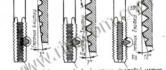
To manually cut metric or inch threads, use a set of hand taps, usually consisting of three pieces (Fig. 5), which sequentially pass through the hole being cut. The first and second taps are used to pre-cut the thread, and the third is used to clean the thread, giving it its final dimensions and shape. The number of each tap in the set is recognized by the number of marks on the tail: No. 1 has one mark, No. 2 has two marks, and No. 3 has three marks. Sometimes, to cut small threads in through holes, a set of two taps is used, of which No. 1 is used for preliminary cutting, and No. 2 is used for final cutting.
Fig.5
To cut threads in through holes with a length not exceeding the thread diameter, nut taps with a long chamfer are used, which are used to cut threads in one pass.
Preparing the hole for the thread. When making threads with taps, small holes are usually tapped immediately after drilling; Large holes are pre-bored. It is very important to ensure the correct diameter of the thread hole; it should be slightly larger than the internal diameter of the thread. The material of the cut nut, under the influence of the cutting force, flows somewhat into the grooves of the thread. The more viscous the material of the part, the stronger it flows and, therefore, the larger the diameter of the hole should be.
The diameters of the threaded holes are selected according to the tables. In table 1 shows some hole diameters for metric threads.
Table 1
Threaded hole diameters
The length of the blind holes for threads should be greater than the length of the thread by at least the size of the tap part, i.e. by two or three threads.
Techniques for cutting threads with a tap.
When cutting a thread with a tap on a lathe, the part to be cut is installed and secured in the chuck so that the axis of the part's hole coincides with the axis of rotation of the spindle. The tap is installed as shown in Fig. 6. Its intake part is inserted into the hole to be cut, and the tail part is fixed in the device. The device for securing the tap consists of a mandrel 4 with a key 3 and a sleeve 2 with a groove into which the key 3 fits. The tap is secured with two bolts in the square hole of the sleeve 1. The mandrel 5 has a conical shank inserted into the hole of the tailstock quill.
Rice. 6
When cutting a thread, the tap is brought to the hole of the part using a handwheel that moves the quill; the tapping part of the tap is inserted into the holes being cut. To cut the first turns of the thread, you need to carefully and evenly press the tap while rotating the tailstock handwheel.
As soon as the tap cuts into the hole by 1-1.5 turns, its further movement will be carried out by self-tightening due to the rotation of the part. The device shown in Fig. 6 allows you to cut a thread to a given length, upon reaching which thread cutting will automatically stop. When cutting threads in blind holes, before starting work with the next largest tap, it is necessary to remove chips from the hole.
Cutting modes when cutting threads with taps.
The cutting speed when cutting threads with taps should be low; this extends the life of the tap and prevents chip jamming. The following cutting speeds are recommended: for steel 3-15 m/min; for cast iron, bronze and aluminum 6-22 m/min., the depth of cut is built into the design of the tap, and the feed is equal to the thread pitch. Cooling should be plentiful. It is recommended as cutting fluids: for cutting parts made of steel - oil (sulfofresol), when cutting parts made of cast iron, bronze and aluminum - emulsion or kerosene.
Cutting triangular threads with cutters
The most common method of cutting triangular threads on screw-cutting lathes is cutting with thread cutters.
Fig.7
Design of cutters. The shape of the cutting part of the thread cutter must correspond to the thread profile. The profile angle of the cutting part should be 60° for metric threads, 55° for inch and pipe threads. To avoid distortion of its profile when cutting a thread, thread cutters are usually sharpened with a rake angle γ = 0 and the tip of the cutter is set at the height of the machine center line.
There are thread cutters for cutting external threads (Fig. 7, a) and for cutting internal threads (Fig. 7, b). Both can be solid or inserted, rod, prismatic and disk, like shaped cutters. The head of a thread cutter for internal threads must be perpendicular to the axis of the cutter shank.
For finishing passes when cutting threads, spring-loaded holders are sometimes used to produce clean and smooth threads. Such a cutter, encountering a harder part of the metal on its way, is slightly pressed out and does not spoil the thread, but the latter turns out to be less accurate.
Fig.8
In Fig. Figure 8 shows a spring holder 1 with a cutter. Bolt 2 is used to secure the insertion thread cutter 3 in the holder. The peculiarity of this Holder is that it can work as a spring or as a rigid one. This is achieved using screw 4; when the screw is inserted into the slot, the holder acts as a rigid holder; when screw 4 is removed, it acts as a spring. Rough cutting is carried out with a cutter fixed in a rigid holder, and finishing cutting is done with a cutter fixed in a spring holder.
Installation of thread cutter. Setting up the thread cutter requires a lot of attention. The cutter must be installed exactly at the height of the centers, otherwise the thread profile will turn out incorrect. In addition, the middle line of the cutter profile must be perpendicular to the axis of the part (Fig. 9, a). This condition is mandatory when cutting both external and internal threads. If we neglect this, the thread profile will turn out to be asymmetrical (turned to the side), as shown in Fig. 9, b.
Fig 9
The thread cutter is installed using a template, as shown in Fig. 9 when cutting external threads and in Fig. 10 when cutting internal threads. To check, apply the template to the cylindrical (end) surface of the part in the horizontal plane and insert the cutter into the cutout of the template. The correct installation is judged by the clearance between the cutting edges of the cutter and the template cutout. If there is a large gap, it is eliminated by rearranging the cutter, after which the cutter is firmly fixed in the tool holder.
Rice. 10
Thread dies
External and internal triangular threads can also be cut using thread dies.
Thread combs, unlike conventional thread cutters, have on the cutting part not one, but several teeth made according to the shape of the thread profile.
The combs are flat rod ones (Fig. 11, a); prismatic (Fig. 11, b); round with screw thread (Fig. 11, c).
The working part of the comb consists of cutting and calibrating teeth. The cutting teeth (there are usually two or three of them) are cut at an angle φ so that each subsequent tooth cuts slightly deeper than the previous one (Fig. 263, a and b). The calibrating part, which follows the cutting part, also has several teeth (two or three) and is intended for cleaning threads.
Fig.11
When cutting threads with combs, by distributing the load between several teeth, it is possible to increase the transverse feed and thereby reduce the number of passes compared to thread cutters. The combs last longer than threaded cutters. Prismatic combs are fixed in special holders, as shown in Fig. 11, b and install them in the tool holder exactly at the height of the centers.
Round screw combs (Fig. 11, c) are much more widely used when cutting triangular threads, both external and internal, as they are easier to manufacture. They consist of several screw turns. The working part of these combs also has several cutting teeth, cut at an angle, and several calibrating teeth.
When cutting external threads, the thread direction of a round screw comb must be opposite to the direction of the thread on the part, i.e. if you need to cut a right-hand thread, then the comb must have a left-hand thread.
When cutting an internal thread, the direction of the thread of the round screw comb must coincide with the direction of the thread of the part, i.e., for example, when cutting a right-hand thread, the comb must also have a right-hand thread.
Content
Section 1 Foundry……………………………………….. 2
§ 1 Fundamentals of Foundry…………………………………….. 2
§ 2 Casting into disposable molds………………………………………………………6
§ 3 Special casting methods…………………………….. …………..10
Section 2. The essence of pressure processing of materials……………. 16
§ 4. General information about pressure treatment. Rolling…………….. 16
§ 5. Pressing and drawing……………………………………………………….21
§ 6. Forging, stamping…………………………………………………………………… ….23
Section 3. Processing of materials by cutting…………………………..40
§ 7. The process of cutting metals………………… ………………………..40
§ 8. Turning……………………………………… ………………………..57
§ 9. Milling…………………………….. ……………………… .58
§ 10. Drilling, countersinking and reaming. …………………….. .59
§ 11. Thread cutting……………………………………………………………………. .65
How to cut threads
To cut threads, you will need the following tools:
- tap, set of thread-cutting tools, dies;
- drilling machine with speed control;
- electric drill with low speed operating mode;
- a set of drills for creating holes in parts;
- vice for fixing the workpiece;
Machine-hand taps are designed for manual use or for mounting in a drill chuck. For machine use, the designs are distinguished by an extended shank. It will not be possible to install a tap holder for manual threading on it.
- hammer;
- core for creating marks for drilling holes;
- a lubricant that prevents the tool or workpiece from overheating during processing;
- rags to remove oil after work.
Dies and taps for cutting
How to correctly determine the hole diameter
Before cutting internal threads, it is necessary to make a hole in the workpiece in advance. Its dimensions must be selected strictly, since exceeding the optimal value will not allow you to create a strong bolt connection, and reducing it will increase the likelihood of damage to the tool during operation.
To determine the diameter of the hole for a standard thread, you will need to use reference books. To create non-standard threads, you need to make simple calculations: subtract the pitch size from the diameter.
How to cut threads
Thread cutting is quite simple, but requires special care when working and a precise sequence of actions. The choice of cutting method will determine the list of tools used and the features of preparing the part for processing.
You will need a technical reference book with data on the sizes of the tools used. The thread pitch can be found on the tap used.
Preparing for thread cutting
Cut the thread only after completing the preparatory work:
- in the directory they look for the necessary information on the diameters of cutting tools for further selection;
- collect the tools needed for work;
- use a core to mark the location of the hole for the internal thread, then drill it with a drill;
- for external cutting, prepare a workpiece of the required diameter on a milling machine and cut a chamfer;
- clean the surface of the workpiece from dirt and oil stains, then apply lubricant to it and the tool.
Thread cutting tool
Work order
Only after the preparatory work should you start processing the workpiece, since otherwise it will not be possible to cut the thread correctly. Step by step cutting is done like this:
- It is necessary to firmly fix the workpiece in a vice to prevent rotational or translational movements deviating from the original position.
- Depending on the type of thread, chamfer (external) or drill a through or blind hole using a drill. Drills with sharpening angles are used, depending on the hardness of the material, but not more than 1400.
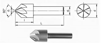
- The hole needs to be chamfered with a countersink. The depth should be in the range of 0.5-1 mm, selected based on the dimensions of the part and the thread diameter.
- Cutting is performed with a tap or die. The cutting part must be lubricated.
- Cleaning the surface from chips using brushes.
When cutting, you need to sequentially use tools numbered 1 to 3, included in the kit. To increase the speed of work, it is not allowed to use large numbers without using the previous ones. The last number is used to form the finishing turns, without which the screw may jam when screwed in.
Decoding the writing of threads
Regulatory documents: GOST, OST, MN for a specific type contain samples of conditional recording.
Graphic materials are designed in accordance with the instructions of GOST 2.311-68 “Image of threads”.
A typical designation structure contains:
- the literal part defining the type;
- numbers corresponding to the nominal size in millimeters or inches;
- pitch (mm) is indicated only as fine, after the “×” sign;
- for multi-start ones, instead of the previous paragraph, the stroke (mm) is given, then the step in parentheses;
- direction: right is the default, left is LH;
- tolerance range or accuracy class;
- make-up length other than normal.
Example 1: М16×1.5LH–6H. Explanation:
- M – metric cylindrical;
- 16 – nominal diameter, mm;
- 1.5 – fine pitch, mm;
- LH – left;
- 6Н – tolerance range, where 6 – degree of accuracy; H – main deviation. Capital letters are used for internal (nuts), hence the threads in the hole.
The screw-in length is not indicated, which means it is normal.
Example 2: G1/2–A
- G – cylindrical pipe;
- 1/2 – thread size, inches; corresponds to the internal diameter of the pipe;
- A – accuracy class.
The designation options are illustrated below.