Advantages and disadvantages of jet units
Among the main advantages of such units are a simple and reliable design, durability in operation, reliability and lack of sensitivity to aggressive environments. To a large extent, these advantages are due to the fact that jet pumps are free of moving parts, which in other pumps quickly wear out. By the way, this same design feature allows pumps to be manufactured in small sizes, which also affects the minimization of maintenance costs. But there are also disadvantages to such devices, including the need for special preparation of working fluids and low performance indicators.
Principle of operation
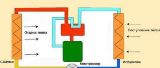
Almost all water-jet units operate on the principle of kinetic energy, which is formed during the process of water exiting a constricted nozzle. During operation, such systems provide so-called dry suction, which creates a deep vacuum. It is also important to note the pressure factor, without which it is impossible to operate a jet pump. The principle of operation in the context of pressure is determined by the different conditions of fluid passage in narrow and wide sections of the pipe. When liquid moves from a narrow section of pipe to a wide one, the pressure increases, and vice versa. In some way, such movements create a spring effect, pushing out water in the working circuit.
The dependence of pressure in a pipe on speed is explained by Bernoulli's law. According to its formulation, jet pumps draw energy from the artificial narrowing of pipes in the nozzles and in individual technical sections, which makes it possible to adjust both the pressure in the working medium and the flow speed indicators.
Shaft and bearings
Whatever type of wheel is used, it is mounted on a rotating shaft. The shaft must be secured in the housing with bearings in one of 2 ways:
- Console
- Symmetrical
Cantilever fastening
When the shaft is cantilevered, the impeller is fixed at one end and the bearings at the other.
This design places the suction and discharge ports perpendicular to each other, and the suction port directly in front of the center of the wheel.
Such pumps are called end suction pumps. They are widely used because they are cheap and easy to produce, but they have one drawback related to the path of fluid movement.
During pump operation, a low pressure zone is created in the suction port.
There is a high-pressure zone at the outlet of the wheel, from which the energized fluid enters the spiral casing.
Fluid flows towards the rear plate in open and semi-open wheels, which completely destroys the pressure balance. As a result, an axial force or load occurs - pushing the wheel towards the suction hole.
This can be compensated for by installing stronger bearings or drilling holes in the wheel plate to equalize the pressures. But these are not effective methods.
Symmetrical mounting
A more effective solution is to place the shaft on bearings on both sides. This is called symmetrical design.
Shaft support is improved not only by the placement of bearings on both sides, but also by the ability to use symmetrical closed wheels with double suction.
Since there are the same high and low pressure zones on both sides of the wheel, this successfully eliminates loading forces due to the balance of pressures. This design also has another advantage. The suction and discharge ports are located parallel to each other on opposite sides of the pump, and the housing is axially divided.
By simply unscrewing the bolts and removing the cover, the service technician can access the rotating part of the pump inside without removing the entire pump from the system.
Due to the separate axial design, pumps with a symmetrical bearing arrangement are called split-casing pumps.
All of these, of course, are very good reasons to install such a pump in your mine right now. But there are some disadvantages. Because maintenance operations and sealing requirements are more complex for split casing pumps than for end suction pumps. They are also more expensive.
Jet Pump Maintenance
To activate the jet pump, you just need to prepare the system pipelines and supply the working fluid to the nozzle. Multistage steam-air ejectors are put into operation sequentially, starting with the last stage operating into the atmosphere. The normal operation of the stage and the entire ejector is judged by the readings of the vacuum gauges. A failure in the operation of one of the compression stages leads to a failure in the operation of the entire ejector. A breakdown in operation can occur due to a violation of the cooling mode of the condensers, and more often due to clogging of the nozzles with scale, dirt, and salt deposits.
Water jet ejectors of the dehumidification system pump water overboard through non-return controlled valves. When the ejector is put into operation together with the working water in the first period, air is removed from the suction line overboard, and at low tide an intermittent stream of milky color is observed. In the future, the normal operation of the ejector is judged by the position of the drain valve lever, which should be in the open position and vibrate slightly. A decrease in ejector flow can occur when the receiving filters (grids) on the suction pipeline are clogged. For all jet pumps, a decrease in flow and unstable operation (up to failure) are observed when the pressure of the working fluid decreases or when the tightness of the suction pipeline is broken (due to air leaks).
During routine preventive inspections of jet pumps, special attention must be paid to the cleanliness of the internal surface, the condition and dimensions of the flow part of the nozzle, as well as its installation in place, i.e., to alignment and compliance with the distance specified in the form from the nozzle end to the diffuser neck .
In preparation for launching a steam jet ejector, cooling water is supplied to the ejector cooler, the secant valve is opened and the working steam steam line is blown through the ejector. After this, the steam pressure in front of the nozzle rises to normal and, as soon as the vacuum gauge shows a normal vacuum value, the air suction valve to the ejector slowly opens. The ejector of the last stage is put into operation first, the remaining stages are introduced as needed.
During operation of the steam jet ejector, the normal supply and temperature of water in front of the ejector cooler, the pressure of the working steam and the magnitude of the vacuum are monitored.
When the steam jet ejector stops, the intake air valve and the working steam valve are closed, and after the refrigerator has cooled sufficiently, the water supply to it is stopped.
The water jet ejector is started by opening the working water supply valve and the suction valve.
The water jet ejector is stopped by closing the suction and working water valves.
When preparing the injector for start-up, the water inlet valve and the feed valve on the boiler open. Then the secant steam valve opens and the starting valve handle is slowly moved. As soon as all the air comes out of the pilot pipe and water appears, the start valve opens to the required amount.
You should start the injector carefully so as not to get burned by the steam coming out of the pilot pipe.
What types of water jet installations are there?
The equipment is designed in many configurations and modifications. Water jet pumps are made from various materials:
- Glass;
- Metal;
- Plastic.
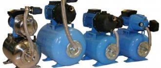
Plastic and metal vacuum systems are not only more reliable and durable, but also more durable. They are equipped with a variety of additional equipment: a union nut with a reliable gasket for a high-quality connection with the main water tap, a shut-off valve, a single safety valve, and a pressure gauge.
The advantages of water jet units are their ease of use, as well as the ability to pump out water and sand. They are insensitive to its quality. The vacuum pump has one serious drawback - high water consumption with a low efficiency.
The hydraulic elevator is included in the kit of each fire truck. It is used to collect water from water sources. Especially those that are difficult to access by car, or swampy banks of rivers and lakes. The fire hydraulic elevator is an ejector type pump. In such devices, water flows through a hose attached to the head at the elbow, and then into the nozzle.
German-made jet pumps have proven themselves well on the market.
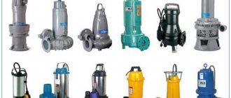
Artesian pumping systems are:
- Deep, they are suspended from the well;
- Electric submersible, which are connected to an electric motor and installed in a well below the water level.
Jet pumps are practically not used in traditional water supply and irrigation systems. They have found their application under conditions of increased loads. They handle chemicals and contaminated environments very well while maintaining original performance characteristics. They have the advantages of being easy to use and not requiring a compressor.
All of the above devices are used both industrial and household. In many areas of human activity, such devices are necessary and very important; they cope with many tasks in which other technology is powerless.
Technical parameters of jet pumps
All jet pumps most often have low production characteristics. This is especially true for household units. Thus, devices for home use are capable of pumping water from a well in a volume of only 15-17 l/sec. At the same time, a more complex professional mechanism supplies from 30 to 50 liters of water per second. But this indicator also creates a higher price for the mechanism.
The height of water rise for the simplest jet pump does not exceed 15 meters. Sometimes there is a possibility of liquid rising from a depth of 20 meters, but in this case, productivity and efficiency will be reduced even more. If the question is about more complex and powerful equipment, then the jet unit is capable of lifting water from a depth of 50 meters.
Important: this is why the use of jet pumps has found application in the case of operating sand or limestone wells for domestic and economic needs.
General information
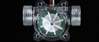
Features of the unit
Jet pumping devices help move substances in different states of aggregation through pipes equipped with a nozzle having a narrowed structure. As the device narrows, the flow rate increases. The energy with which the fluid moves is converted into kinetic energy.
This type of equipment is not a standard injection device, since it does not provide strong pressure in the area of injection-type pipe rolling. In the pumping apparatus, a double energy conversion of the flow occurs.
Device Basics
A liquid medium moves towards the tapering nozzle under the influence of pressure. The flow emanating from the nozzle makes the pressure in the mixing compartment lower than in the atmosphere. Another stream, the medium being processed, is mixed with the liquid, and it flows into the working compartment.
When the working type of liquid is mixed with the injected one, the pressure values with the flow rate are equalized. The thoroughly mixed media flow into the outlet diffuser. In it, the kinetic energy of the medium decreases and the potential energy increases. At the outlet of the diffuser, the volume of potential energy becomes such that it can flow to a consumption unit, for example, into a container where liquid is collected.
Horizontal single-section two-stage air ejector
Air ejectors are now installed on many ships.
Inside the mild steel condenser body, which houses a single-section, two-stage air ejector, is a bank of U-shaped tubes.
The cooling medium is condensate from the main or auxiliary condenser flowing inside the pipes, and the steam-air mixture passes in the housing outside the pipes. Under the influence of the vacuum created by the high-pressure steam jet, steam and non-condensable gases from the main condenser are sucked into the 1st stage ejector. Their mixture is discharged into the intermediate condenser or the 1st stage capacitor.
Most of the steam, falling on the cold pipes of the intermediate condenser, condenses, and the condensate flows to the bottom of the housing, and from there it goes down to the main or auxiliary condenser. The remaining part of the steam and non-condensable gases is sucked in by the 2nd stage ejector and pumped into the 2nd stage condenser, from where the condensate is drained, and the non-condensable gases are released into the atmosphere through the vacuum maintenance valve.
Each ejector stage (Fig. 2.38) consists of a mild steel housing housing a Monel metal nozzle and a gunmetal diffuser. To compensate for thermal expansion, a sliding support is provided on the inlet side.
As mentioned above, air and non-condensable gases are released through the vacuum maintenance valve (Fig. 2.39). This device, which prevents vacuum leakage if the air ejector fails, is mounted in a pocket of the 2nd stage condenser housing and is equipped with a thin stainless steel ring plate that seals the holes in the gunmetal valve seat at 2-stage condenser pressure. th steps below atmospheric. If the pressure in the condenser exceeds atmospheric pressure, the valve rises and releases gases to the atmosphere. In two-section installations, a safety valve is installed on the housing of the 1st stage condenser.
Air ejector. Steam jet ejectors are used to remove air and other gases released from the water from the condenser. In each of the ejector stages, high-pressure steam expands in a Laval nozzle. The working steam leaves the nozzle at a speed of 1220 m/s and transfers part of its kinetic energy to the air mass. The resulting steam-air mixture passes through the diffuser, and there its kinetic energy is converted back into pressure energy. Since the maximum pressure ratio in one stage is 5:1, it is necessary to ensure a series connection of two or even three stages in order to obtain a vacuum of about 725 mm Hg with a sufficiently low steam flow rate. Art.
A large number of ejectors of various designs are used on ships, but they all work on the same principle. For ejectors of the old design, diffusers are placed in a cast steel casing that serves as a steam condenser.
The diffusers are located vertically. Steam is supplied from above (see Fig. 2.40). In the newest designs, both vertical and horizontal diffusers are moved outside and the steam condenser housing has a lighter design. Some designs combine air ejectors with a steam condenser from the seal.
Scope of application of the jet unit
Although the efficiency of pumps of this type is not high, in some cases such mechanisms are used quite widely and often due to the principle of their operation. The main use of units of this type is noted in the following industries:
- Food industry;
- Fire extinguishing or sewage systems;
- Air conditioning and ventilation systems;
- Heat and gas supply communications;
- In combination with vane (centrifugal) pumps to increase overall efficiency;
- As an auxiliary equipment for air intake from the working chamber of a centrifugal pump and its water inlet pipe.
Rules for operating jet pumps
When assembling the pump, it is necessary to ensure the alignment of the nozzle and diffuser, as well as the correct installation of the annular gap - the distance from the end of the nozzle to the inlet diameter of the diffuser - which should be 0.35D - (D is the inlet diameter of the diffuser). The annular gap is set according to the factory instructions. There should be no nicks or burrs on the nozzles.
Before putting the ejector into operation, you must:
- 1) open the working water supply valve (quickly);
- 2) open the water intake valve to the ejector.
Malfunctions:
The pump does not provide suction and does not provide full performance:
- a) Incorrect start;
- b) Clogging, air leaks at the suction due to a malfunction of the suction tract;
- c) Clogging and wear of the nozzle, the annular gap is incorrectly installed;
- d) Suction cavitation.
On vessels of the fishing industry fleet for pumping pulp, i.e. mixtures of fish with water are used in airlifts or hydraulic elevators.
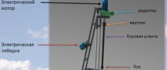
Figure 3.5 shows a diagram of an airlift, which consists of a suction hose 3, a pressure air pipeline 4 and a compressor 5.
Compressed air (0.6-0.8 MPa) from compressor 5 through pipeline 4 enters a special chamber 2. From the chamber, air in the form of bubbles rises up the hose and expands. This reduces the density of the water-air mixture; for this reason, due to the difference between dense water and the water-air mixture and according to the law of communicating vessels, denser water displaces the lighter mixture, which rises to the deck and pours out. Along with the water, fish enters the system through pipe 1 and is supplied to the vessel. The water leaves through the water separator 6, and the fish rolls into the hopper.
Increasing the amount of supplied air reduces the density of the mixture and, just like lowering the mixing chamber, which increases the immersion depth h, increases the lift height to 2.5 m above sea level. The main disadvantage of the airlift is its low efficiency - ŋer - 20-30%.
Literature
Auxiliary mechanisms and ship systems. E. V. KORNILOV, P. V. BOYKO, E. I. GOLOFASTOV (2009) Operation of ship auxiliary mechanisms, systems and devices - Popov V.V. [2021]
Similar articles
- Marine Fist (Rotary) Pumps
- Rotary pumps - classification and application
- Marine piston pump parts
- Maintenance of marine piston pumps
- Adjusting the steam distribution of direct-acting pumps
- Designs of piston marine pumps
- Marine Pumps - Air Caps
- Piston pumps - operating principle and classification
- Main parameters of ship pumps
- Purpose and classification of ship pumps
Rating 0.00 (0 Votes)
Types and classification of pumps
A pump is a type of hydraulic machine that moves fluid by suction and discharge using kinetic or potential energy. The pump is necessary for use in fire-fighting equipment, for draining liquids in residential areas, for supplying fuel and many other purposes. There are different types and types of pumps depending on the area of application, design, and principle of operation. When using pumps for various purposes, you need to know what types there are and how they differ.
Pumps for fire extinguishing systems
The main requirement for fire extinguishing system pumps is the supply of water under high pressure. Centrifugal pumps are the most commonly used because they allow water to be pumped quickly using centrifugal force. Important points when choosing a fire extinguishing pump are:
- pressure;
- wheel speed;
- efficiency;
- suction lift;
- volume of water moved.
Depending on the number of wheels with blades, pumps are single-stage or multi-stage. Multistage units allow you to create higher pressure, which in turn affects the pressure and height of the supplied liquid.
When installing fire extinguishing systems in buildings, it is worth considering that the equipment must be checked periodically, since stagnation can cause difficulties during startup. Fire trucks are equipped with centrifugal pumps and auxiliary units.
Auxiliary pumps fill the centrifugal pump housing with liquid and turn off automatically.
Oil and fuel pumps
Industrial types of pumps include oil and fuel devices installed on automobile and machine engines and internal combustion engines.
Oil pumps reduce friction between interacting engine parts. They are adjustable and unregulated. Car engines are equipped with rotary or gear pumps for pumping oil.
Fuel pumps are installed in cars without fail. They ensure the delivery of fuel from the tank to the combustion chamber. Depending on the design, fuel pumps are either mechanical or electric.
Submersible pumps
Submersible pumps are used when working at a depth of more than eight meters. All types of submersible pumps have a cooling system and are also made of durable material that helps avoid deformation under pressure. Submersible pumps are either centrifugal or vibration pumps. In the second type of pumps, liquid is sucked in using a vibration or electromagnetic mechanism.
When choosing a pump, it is important to consider a large number of factors:
- purpose of use;
- place of use;
- the need to install auxiliary units;
- pump dimensions;
- pump operation method.
(5 5.00 out of 5) Loading…
Ejectors and injectors
An ejector is usually called a jet pump designed to remove water or air from a room or device. The ejector is always connected to the object being served by a suction pipe.
Steam jet ejectors are used mainly as vacuum devices and sometimes as fans in explosive areas.
Domestic vacuum steam jet ejectors are designated by the brand PEZh with the addition of a numerical index and are manufactured in one-, two- and three-stage versions. Single-stage ejectors are used to create a vacuum of up to 80%, and two- and three-stage ejectors - up to 96-97%.
A two-stage steam jet vacuum ejector is shown in Fig. 32. Each ejector stage can operate independently.
The right side is the ejector of the first stage, the left is the second stage, since when the ejectors are made in stages, their counting order is from the object being served. The diameter of the narrow part of the nozzle and diffuser is 2.5 and 13.5 mm for the first stage and 6 and 16.6 mm for the second stage. Working steam with a pressure of 6-7 kg/cm2 is taken to the ejector from the ship's steam boiler. In general, the working steam pressure in front of the ejectors reaches 14-16 kg/cm2.
Water-jet ejectors are more widely used on modern ships than steam-jet ejectors. Water-jet ejectors are used as vacuum, drainage, booster, fish pumping, etc. means.
Domestic drainage ejectors are designated by the VEZ brand, with the addition of a numerical index. For example, VEZH-20/11P: water-jet ejector with a capacity of 20 t/h with a working water pressure of 11 kg/cm2, portable. The consumption of working water for drainage ejectors is large and reaches 70%; on their performance. The suction height is 2-4 at a water pressure of 5-6 m. Art.
Vacuum water-jet ejectors are used for joint or separate removal of water-air mixture from serviced objects. Compared to steam-jet vacuum ejectors, water-jet vacuum ejectors are much more stable and reliable in operation and are capable of creating a vacuum of up to 94-97% in a single-stage design. The working water pressure of the ejectors is 20–70 m of water. Art. and sometimes higher, back pressure 8-10 and backwater at least 1.5 m of water. Art.
The vacuum water-jet ejector is shown in Fig. 33. Similar ejectors with a ratio of 8/15; 11/21; 11/25; 13.4/25, etc. are widely used in modern vacuum evaporation plants and can be used successfully for pumping water. The numerator of the fraction means the diameter of the narrow part of the nozzle, and the denominator means the narrow part of the diffuser, in millimeters. Of great interest is the use of vacuum water-jet ejectors in auxiliary condensing units on ships.
An injector is a jet pump capable of creating a pressure exceeding the pressure of the working steam. The working fluid in the injector is only steam and only water is pumped. The injector is connected to the serviced object by a discharge pipe.
The ability of the injector to create pressure higher than the working one is explained by the condensation of the working steam in the mixing chamber. As a result of condensation, the volume of condensate becomes much smaller than the volume of steam, the energy consumption for compressing the mixture is significantly reduced, and the energy of this mixture is sufficient to create a high pressure of the injector. The more completely the condensation of the working steam occurs, the better the injector will work. The temperature of the pumped water should be as low as possible and not exceed 40° C.
Injectors are usually used as feed supplies for steam boilers.
The restarting injector and its connection diagram are shown in Fig. 34.
The intake of working steam into the injector is carried out by opening the start valve manually using a handle. The jet of working steam coming out of the nozzle creates a vacuum in the mixing chamber and water is sucked into it. To prevent excess working steam, a sharp increase in vacuum and boiling of water in the mixing chamber, the start valve must be opened small and slowly.
When the injector is started, the air sucked from the line accumulates in it and the energy of the mixture of working steam and air is only sufficient to open the pilot valve.
Through this valve, the steam-air mixture exits through the conductor pipe into the atmosphere. As soon as water begins to flow out of the lead pipe, the opening of the start valve increases. With the entry of water, the steam condenses and the energy of the mixture of water and condensate increases. The water in the cavity of the pilot valve is entrained by the jet into the discharge cone and a vacuum is formed under the valve. The valve closes under the influence of atmospheric pressure and spring pressure, and the discharge valve opens and water is supplied to the boiler. The heat from the working steam is used to heat water.
Flaws
Like all simplified designs, water jetting stations are not capable of providing high performance, so their efficiency at best reaches 70%. In addition, they require constant connection of power supplies for the initial supply of liquid to the nozzle. Another disadvantage that jet pumps have is their low autonomy. The very principle of operation implies dependence on environmental conditions that must be created by third-party resources - and this is another item in the costs of maintaining the function of this equipment.
Varieties
The pump's energy can be used to both pump and suction liquids. In this regard, injection and ejector units are distinguished. In the first case, the guide pipe is necessarily used, which is connected to the target receiving device - that is, the reservoir where the water is collected. The main task of injectors is to collect liquid, although after performing this function a vacuum is also formed. Jet fire pumps operate on this principle, which includes a receiving chamber, a nozzle with a neck, a diffuser and a main pipeline. The main task in organizing the fire extinguishing process with a water jet unit will be to correctly configure the parameters for releasing liquid under pressure. As for ejector pumps, they, on the contrary, focus on the formation of a vacuum. That is, the characteristics with which the selected liquid will be released are not so important in this case, although they will directly depend on the parameters of suction from a specific medium.
Features of operation
It is possible to integrate the pump into the operating infrastructure only after the compatibility of the unit with the serviced liquid has been analyzed. As for work activities, the list of tasks of the operating personnel will include maintaining a sufficient volume of fluid in the pump channel and ensuring an adequate level of safety. Typically, jet pumps are equipped with a wide range of measuring sensors and instruments that indicate the pressure level, speed of movement of the working fluid, temperature, etc. The user must monitor these values, comparing them with the recommended ones. Stopping the unit begins with closing the valve. Next, the remaining liquid is pumped using forevacuum and the structure is physically disconnected.