Information about the manufacturer of the vertical drilling machine 2N106P
The manufacturer of vertical drilling machines model 2N125L is Molodechno Machine Tool Plant MSZ , founded in 1947.
The plant was founded in 1947 and is one of the oldest enterprises in the machine tool industry in the production of vertical drilling machines.
Machine tools produced by the Molodechno Machine Tool Plant
- 2A106P
high-precision tabletop drilling machine Ø 6 - 2N106P
high-precision tabletop drilling machine Ø 6 - 2N118
vertical drilling machine Ø 18 - 2N118-1
vertical drilling machine Ø 18 - 2N125L
vertical drilling machine with rotary table Ø 25 - 2С108П
high-precision tabletop drilling machine Ø 8 - 2054m
semi-automatic thread-cutting machine for cutting threads with M8 taps - 2056
semi-automatic thread-cutting machine for cutting threads with M18 taps
2N125L Vertical drilling machine. Purpose, scope
Vertical drilling machine model 2N125L with a rotary table, with a nominal drilling diameter of 25 mm, is used in enterprises with single and small-scale production and is designed to perform the following operations: drilling, reaming, countersinking, countersinking, reaming and trimming ends with knives and is used in auxiliary and the main non-mechanical shops of machine-building plants, as well as in the repair services of non-mechanical enterprises.
2N125L machine can process parts mounted both on a table and on a plate. The presence of a round rotary table allows you to process holes in parts without moving them.
The vertical drilling machine model 2N125L is designed to perform a wide range of drilling operations: drilling, reaming, countersinking, reaming. The machine allows thread cutting with manual spindle reversal control. The machine can process parts on a foundation plate. The presence of a round rotary table allows you to process holes in parts without moving them around the table (or with minor movement), which greatly facilitates the maintenance of the machine.
Operating principle and design features of the machine
2N125L machine belongs to the design range of medium-sized vertical drilling machines (2N118, 2N125, 2N125L, 2N135, 2N150, 2G175) with a nominal drilling diameter of 18, 25, 35, 50 and 75 mm, respectively. Compared to previously produced machines (with index A), the new range of machines have a more convenient location of the gearbox and feed control handles, better appearance, simpler technology for assembling and machining a number of critical parts, and a more advanced lubrication system. The aggregate layout and the ability to automate the cycle ensure the creation of special machines based on them.
The limits of spindle speeds and feeds make it possible to process various types of holes using rational cutting conditions.
of mechanical spindle feed on 2N125L
Allows processing of parts in a wide range of sizes from various materials using tools from high-carbon and high-speed steels and hard alloys.
On the 2N125L , thread cutting with manual reversal of the spindle is allowed.
2N125L machines are equipped with a device for reversing the main motion electric motor, which allows them to cut threads using machine taps while manually feeding the spindle.
Placement category 4 according to GOST 15150-69.
Where is it used?
Like the famous 2N135 unit, the 2N125 model is designed for low production volumes. The equipment is ideal for installation in a small small-scale workshop, as well as for work in domestic conditions. The 2n125 drilling machine has a nominal drilling diameter of 25 millimeters. With its help, you can not only drill and ream holes, but also perform a number of other operations.
At the same time, the machine operator can independently select the speed and spindle feed mode, which allows optimal use of equipment resources to perform a specific task. The machine is capable of working with a wide variety of holes and materials as efficiently as possible, which is also worth noting as an advantage of the model. The equipment belongs to placement category 4 in accordance with GOST 15150-69.
Since this model has been around for decades, it would be crazy if such a popular technique had not undergone a single modification throughout its existence. In this regard, the manufacturer took care of satisfying the most specific needs of the craftsman, offering several possible variations of the 2n125 drilling machine
This is interesting: Lathes
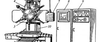
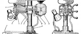
Location of the main parts of the drilling machine 2N125L
Location of the main components of the drilling machine 2n125l
List of main parts of the drilling machine 2N125L
- Drive 2N125L.21.000
- Rotary vice*) 2N125L.60.000
- Cooling 2N1251.80.000
- Electrical equipment 2N125L.90.000
- Gearbox 2Н1251.20.000
- Feed box 2N1251.30.000
- Spindle 2N125L.50.000
- Column, table, plate 2N125L.10.000
- Table lifting mechanism 2N125L.11.000
- Drilling head 2N125L.40.000
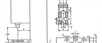
Dimensions of the working space of the drilling machine 2N125
Drawing of the working space of the drilling machine 2N125
| Machine model | Morse cone | A | B | IN | D | D1 | M |
| 2N125 | 3 | 250 | 700 | 60 | 45 | 23,825 | 400 |
| 2N135 | 4 | 300 | 750 | 30 | 60 | 31,267 | 450 |
| 2N150 | 5 | 350 | 800 | 0 | 80 | 44,399 | 500 |
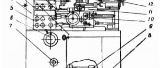
Location of controls for drilling machine 2N125L
Location of controls for drilling machine 2n125l
List of controls for drilling machine 2N125L
- Input switch
- Spindle left rotation button
- Right spindle rotation button
- Network control lamp
- Stop button
- Gear shift knob
- Feed shift knob
- Manual feed button
- Feed handle
- Cam for adjusting the processing depth
- Square for manual movement of the drill head
- Cooling switch
- Spindle rotation toggle switch
- Light switch
Machine design features
Description of the unit design includes:
- gearbox;
- drive unit;
- feed box;
- drill head;
- spindle;
- rotary vice;
- electrical equipment.
Operating principle of the gearbox:
- communication of revolutions to the spindle using two movable triples;
- the box shaft supports are located in the upper and lower plates, held together by 4 ties;
- The electric motor drives the gearbox through a gear train and clutch;
- the last shaft of the box has the form of a hollow sleeve, its splined hole transmits rotation to the machine spindle;
- The gears of the box are switched using a handle.
This is interesting: Homemade CNC milling machine: assemble it yourself
Design of the main components of the vertical drilling machine 2N125L
Gearbox
The gearbox (Fig. 6) imparts different speeds to the spindle, which is carried out by two movable triples. The gearbox shaft supports are located in two plates: the upper 5 and the lower I, which are tightened together by four ties 4. The gearbox mechanism is driven into rotation by an electric motor through an elastic coupling and a gear drive. The last shaft of the gearbox is a hollow sleeve 3, the splined hole of which transmits rotation to the machine spindle. Gear 2 of the feed box drive is attached to the same sleeve.
The gearbox gear blocks are switched from one handle, which has three fixed positions around the circumference and along the axis. Handle 6 is located on the front surface of the drilling head and, through gear 7 and circular rack 8, moves two rods 9 and 10, on which forks are attached, connected to switchable blocks. Additional fixation of the position of the gear blocks is carried out by fixing the rods 9 and 10 using ball clamps. All gearbox shafts are splined, which greatly simplifies assembly. All gearbox mechanisms are assembled separately and mounted in the drilling head. The gearbox mechanisms, as well as other mechanisms in the drilling head, are lubricated by a gear pump located in the feedbox. To control the operation of the oil pump, there is a special oil indicator in the drive housing.
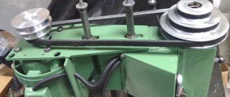
Machine drive
The drive (Fig. 7) serves to provide an elastic connection between the electric motor shaft and the machine gearbox.
The drive consists of a separate housing I on which the electric motor is mounted. A coupling half 2 is attached to the electric motor shaft, which, using pins 3 and a rubber ring 4, transmits rotation to the gear half-clutch 5. The gear half-coupling meshes with the primary gear of the gearbox.
Gearbox
The feed box (Fig. 8) is a three-shaft mechanism mounted in a separate cast housing 4. The feed box is driven by gear 5 sitting on the sleeve 3 (Fig. 6) of the gearbox.
On the first shaft of the feed box there is a movable gear block 2 (Fig.) , with the help of which three automatic spindle feeds are carried out. The gear blocks are switched by one handle 3, which, with the help of gears 5, moves the fork b associated with the switchable block.
The position of the gear blocks is fixed by fixing the handle 3 and the ball retainer located in the fork 6. Gear I is installed on the output shaft of the feed box, transmitting rotation to the worm of the feed mechanism.
The safety clutch serves to turn off the mechanical feed when the specified processing depth is reached and is located on the input shaft of the drilling head.
Drilling head of vertical drilling machine 2N125L
Drilling head of vertical drilling machine 2n125l
The drilling head (Fig. 9) is a box-section cast iron in which all the main components of the machine are mounted: speed box, feed box, spindle and feed mechanism.
The first three units are assembled separately and attached only to the drilling head.
The feed mechanism, consisting of a worm gear, a horizontal shaft with a rack and pinion gear, a dial with associated parts, handles, cam and ratchet overrunning clutches, is an integral part of the drilling head.
The feed mechanism is driven from the feed box (see Fig. 8) through an overload clutch and is designed to perform the following functions:
- manual approach of the tool to the part
- turning on the working feed
- manual feed advance
- turning off the working feed
- manual spindle retraction
- hand feed, usually used in thread cutting
The principle of operation of the feed mechanism is as follows: when the steering wheel 8 rotates, the cam clutch 12 rotates towards itself, which rotates the rack and pinion gear shaft 17 through the hub-half-coupling 14. The spindle is fed manually.
When the tool approaches the part, a torque increases on the gear shaft 17, which cannot be transmitted by the teeth of the cam coupling 12, and the hub-half-coupling 14 moves along the gear shaft 17 until the ends of the cam coupling are opposite each other.
During this period, the cam hub-half-coupling 14 rotates freely relative to the gear shaft by 20°. The angle of 20° is limited by the groove on the coupling and pin 10.
On the hub-half-coupling 14 sits a double-sided ratcheting disk 15, connected to the hub-half-coupling by pawls 7. When the hub-half-coupling 14 is shifted to the left, the ratcheting disk 15, overcoming the spring 13, also moves to the left and the teeth of the disk engage with the teeth of the second disk b, attached to the worm wheel 16. Thus, the rotation from the worm I is transmitted to the rack and pinion shaft 17 and mechanical feed occurs.
With further rotation of the steering wheel 8 with the feed of the pawl 7 turned on, the hub-half-coupling 14 slips over the teeth of the inner side of the disk 15 and, thus, the mechanical feed is manually advanced.
When manually turning off the feed by the steering wheel 8, turning it in the opposite direction by 20° relative to the gear shaft 17 on which it sits, the tooth of its cam clutch 12 becomes opposite the cavity of the hub-half-coupling 14, which, due to the axial force arising due to the inclination of the teeth of the disk 15 and a special spring 13, moves to the right and disengages the disks and the mechanical feed stops.
As mentioned above, the feed mechanism allows manual feeding of the spindle using the handwheel 8. To do this, cap 9 must be moved to the left as far as it will go. In this case, pin II enters the groove of coupling 12 and does not allow it to rotate 20°.
A dial 4 is mounted on the left wall of the drilling head, which is driven into rotation through a pair of gears 2 and 5 when the spindle is fed.
The dial is designed to visually measure the processing depth and to adjust the cam to turn off the automatic feed when the desired drilling depth is reached.
To visually measure the processing depth, the tool is manually brought into contact with the workpiece and ring 3 is installed with the left hand in the desired position. The processing depth is measured using a scale on the cylindrical surface of ring 3. To adjust the cam, there is a T-shaped groove on the end surface of the dial body.
Spindle
Spindle I (Fig. 10) is mounted on ball bearings. The axial feed force is absorbed by the front thrust bearing. The bearings are located in the spindle sleeve 2, which, using a rack and pinion transmission, can move along the axis.
The spindle bearings are adjusted using a nut located above the upper spindle support.
The shape and dimensions of the spindle end are made in accordance with GOST 2701-44.
Rotary vice
The vice (Fig. II) is installed in the table bracket. The vice is intended for light drilling work that does not require high precision. The vice can be rotated and installed at any angle relative to the drill axis.
In two mutually perpendicular positions, the vice is clamped by an additional wedge clamp, which is also a lock.
Adjusting the drilling machine 2N125
Spindle assembly for vertical drilling machine 2N125
Spindle assembly for vertical drilling machine 2N125
Spindle 2 (Fig. 11) is mounted on 4 ball bearings. The axial feed force is perceived by the lower thrust bearing, and the tool knockout force is perceived by the upper one. The bearings are located in sleeve 3, which moves along the axis using a rack and pinion pair. The spindle bearings are adjusted using nut 1.
To knock out the tool, use a special device on the spindle head. Knockout occurs when the spindle is lifted by the steering wheel. The holder of the device rests against the body of the drilling head, and the lever 4 rotates around its axis; knocks out the tool.
The spindle of the 2N125 drilling machine is mounted on 4 bearings:
- 21. Upper bearing No. 5-206 , single-row radial ball, 30x62x16 mm, 5 accuracy class
- 20. Bearing No. 5-8106 , thrust ball, 30x47x11 mm, 5th accuracy class
- 24. Bearing No. 5-8306 , thrust ball, 30x60x21 mm, 5th accuracy class
- 25. Lower bearing No. 5-206 , single-row radial ball, 50x80x16 mm, 5 accuracy class
When assembling the machine during the repair process, it is necessary to observe conditions that affect the accuracy of its operation.
Thus, the gap between the guide bushings of the drill head and the quill of the spindle assembly should be no more than 0.01 mm.
When installing the drilling head and table on the column guides, the 0.03 mm probe should not pass into the joint, and all the requirements of GOST 7599-73 section 4 must be met.
The spindle thrust bearings are also subject to adjustment .
To adjust the spindle thrust bearing you must:
- unscrew the plug on the front part of the drilling head of the 2N125 machine or the cover on 2N135 and 2N150;
- install the spindle so that the stopper in the nut is aligned with the hole;
- release the stopper and, turning the spindle, align the hole in the nut with the hole in the drilling head;
- Having inserted a cylindrical rod into the hole of the nut, turn the spindle counterclockwise until the axial play is eliminated and tighten the nut stopper.
Technical characteristics of bearing No. 5-206
Bearing No. 5-206 - single-row radial ball, 50x80x16 mm
This type of bearing is used everywhere in all branches of industry and agriculture. In terms of the number of units sold, this bearing is only inferior to exactly the same one, but one size smaller - 205. Basically, such a bearing is bought as a closed type - 180206, and it is this bearing that is produced in large volumes at bearing factories. The design - radial ball - is designed to absorb radial loads and, to a very small extent, axial loads.
In addition to these two modifications, there are 80206 (closed on both sides with metal washers), 60206 (closed on one side) and 50206 - with a groove along the outer ring for a retaining ring (the latter type is used quite rarely). Bearings are produced mainly of class 6 precision, they are intended for the mass consumer. For the needs of individual industries, various modifications are produced with additional operating requirements (requirements for noise, accuracy, resistance to temperature or chemical influences), increased load capacity (indicated by the letter A to the right of the main designation).
The main manufacturing plants in our country are JSC SPZ (Saratov, 3 GPP), VBF (Vologda, 23 GPP), LLC SPZ-4 (Samara) and 2 GPP (Moscow). The last two factories assemble bearings from Chinese components, produced with quality control from normal metal (unlike brands such as CRAFT, SZPK, hb and others), which makes them lower in price with decent performance characteristics. Bearings for the mass consumer are produced in accordance with GOST 520-2002, special modifications are made in accordance with TU and ETU and are supplied directly from one plant to another, bypassing the dealer network.
You can buy bearings of this type at minimal prices from official dealers of factories.
The approximate price of the product depends very much on the manufacturer and ranges from 34 - 35 (China) to 280 - 300 rubles (SKF). Bearings with protective washers and plugs are slightly more expensive than open ones. Russian bearings are closer in price to Chinese ones, but in quality they are much better.
The bearing has the following characteristics (bearing 6-180206 - closed on both sides with rubber seals, basic design, cage made of ShKh-15 steel):
Imported bearings of this standard size are designated as 6206 /Рх (where x is the accuracy class of the manufactured bearing and varies from 2 to 6) with additional designations of protective washers and plugs as Z, ZZ or 2RS. For example, 6206 2RS is the designation for bearing 180206 adopted by the manufacturer FAG.
Applicability of bearing 180206 (closed, analogue - 6206 2RS) in domestic automotive and agricultural equipment:
Dimensions and characteristics of bearing 206 (50206, 60206, 80206, 180206, 6206)
- Inner diameter (d): – 30 mm;
- Outer diameter (D): – 62 mm;
- Width (height) (H): – 16 mm;
- Weight: – 0.21 kg;
- Ball diameter: – 9.525 mm;
- Number of balls in the bearing: – 9 pcs.;
- Dynamic load capacity: – 25.35 kN;
- Rated speed: – 7500 rpm.
Diagram of bearing 206 of drilling machine 2N125
Technical characteristics of bearing No. 8306
Bearing 8306 is a single-row thrust ball bearing consisting of three parts - two rings (the diameter of one of them is 1 mm less than the one that is mounted directly on the shaft) and a cage on which the rolling elements are located.
Used in industrial equipment in units with axial load. This is a thrust ball bearing (they are easy to distinguish by number: the fourth number from the end is 8), single, of the basic design. It is used in components of machines and mechanisms that are subject to axial loads. The stopper consists of two flat rings (which differ in internal diameter by approximately 1 mm) and a number of balls on a stamped steel or brass separator.
This type is produced at 2 gas processing plants (Moscow), SPZ-4 (Samara), 20 gas processing plants, or KZUP (Kursk). A modification with a brass separator and the sixth class of accuracy - 6-8306 NLSh1 - is produced in Vologda at 23 GPP (VBF brand).
In automotive engineering, it completes special equipment for the ZIL 137 truck.
Imported bearings 8306 (as well as Moscow and Vologda) are marked according to the international designation system - 51306.
Dimensions and characteristics of bearing 8306 (51306)
- Inner diameter (d): – 30 mm;
- Outer diameter (D): – 60 mm;
- Width (height) (H): – 21 mm;
- Weight: – 0.268 kg;
- Ball diameter: – 11.112 mm;
- Number of balls in the bearing: – 11 pcs.;
- Dynamic load capacity: – 40.3 kN;
- Static load capacity: – 66.5 kN;
- Rated rotation speed: – 3800 rpm.
Diagram of bearing 8306 (51306) drilling machine 2N125
Photo of bearing 8306 (51306)
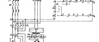
Electrical equipment and electrical circuit of the drilling machine 2N125L
Electrical diagram of a vertical drilling machine 2n125l
Electrical equipment of vertical drilling machine 2N125L
The machine is equipped with a squirrel-cage asynchronous electric motor. The following AC voltages with a frequency of 50 or 60 Hz can be used on the machine:
- power circuit 220, 380, 440 V
- 110V control circuit
- local lighting circuit 24 V
- 24 V alarm circuit
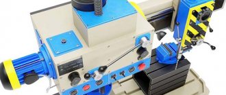
General view of the drilling machine 2N125
Photo of drilling machine 2N125
Photo of drilling machine 2N125
Photo of drilling machine 2N125
Photo of drilling machine 2N125
Photo of drilling machine 2N125
Technical characteristics of the machine 2N125L
| Parameter name | 2N125 | 2N125L | 2N135 | 2N150 |
| Basic machine parameters | ||||
| The largest drilling diameter in steel is 45, mm | 25 | 25 | 35 | 50 |
| The smallest and largest distance from the end of the spindle to the table, mm | 60..700 | 0..700 | 30..750 | 0..800 |
| The smallest and largest distance from the end of the spindle to the plate, mm | 690..1060 | 845..1060 | 700..1120 | 700..1250 |
| Distance from the axis of the vertical spindle to the rack guides (overhang), mm | 250 | 250 | 300 | 350 |
| Desktop | ||||
| Maximum load on the table (center), kg | ||||
| Dimensions of the working surface of the table, mm | 400 x 450 | Ø400 | 450 x 500 | 500 x 560 |
| Number of T-slots Dimensions of T-slots | 3 | 3 | 3 | 3 |
| Maximum vertical movement of the table (Z axis), mm | 270 | 525 | 300 | 360 |
| Table movement per one revolution of the handle, mm | 1,75 | |||
| Spindle | ||||
| Maximum movement (installation) of the spindle head, mm | 170 | 250 | 170 | 250 |
| Maximum movement (stroke) of the spindle, mm | 200 | 150 | 250 | 300 |
| Spindle movement by one dial division, mm | 1,0 | 1,0 | 1,0 | 1,0 |
| Spindle movement per one revolution of the handwheel-handle, mm | 122,46 | 122,46 | 131,68 | |
| Spindle speed, rpm | 45..2000 | 90..1400 | 31,5..1400 | 22,4..1000 |
| Number of spindle speeds | 12 | 9 | 12 | 12 |
| Maximum permissible torque, Nm | 250 | 88 | 400 | 800 |
| Spindle taper | Morse 3 | Morse 3 | Morse 4 | Morse 5 |
| Machine mechanics | ||||
| Number of working feed stages | 9 | 3 | 9 | 12 |
| Limits of vertical working feeds per spindle revolution, mm | 0,1..1,6 | 0,1; 0,2; 0,3 | 0,1..1,6 | 0,05..2,24 |
| Cycle management | Manual | Manual | Manual | Manual |
| Maximum permissible feed force, kN | 9 | 5,6 | 15 | 23,5 |
| Dynamic spindle braking | Eat | Eat | Eat | Eat |
| Drive unit | ||||
| Main motion drive electric motor, kW | 2,2 | 1,5 | 4,0 | 7,5 |
| Electric coolant pump Type | X14-22M | PA-22 | X14-22M | X14-22M |
| Machine dimensions | ||||
| Machine dimensions, mm | 2350 x 785 x 915 | 770 x 786 x 2235 | 2535 x 825 x 1030 | 2930 x 890 x 1355 |
| Machine weight, kg | 880 | 620 | 1200 | 1870 |
- Universal lightweight and simplified vertical drilling machine 2N125L. Operating description 2N125L.00.000 RE, 1983
- Barun V.A. Working on drilling machines, 1963
- Vinnikov I.Z., Frenkel M.I. Driller, 1971
- Vinnikov I.Z. Drilling machines and work on them, 1988
- Loskutov V.V Drilling and boring machines, 1981
- Panov F.S. Working on CNC machines, 1984
- Popov V.M., Gladilina I.I. Driller, 1958
- Sysoev V.I. Handbook for a Young Driller, 1962
- Tepinkichiev V.K. Metal cutting machines, 1973
Bibliography
Related Links. Additional Information
- Classification and main characteristics of drilling-milling-boring group of machines
- Selecting the right metalworking machine
- Machine repair technology
- Methodology for checking and testing drilling machines for accuracy and rigidity
- Directory of drilling machines
- Manufacturers of drilling machines in Russia
Home About the company News Articles Price list Contacts Reference information Interesting video KPO woodworking machines Manufacturers
Cylindrical grinding machine 3m131
The largest diameter and length of the sanded surface: 280X700 mm. Grinding head motor power Nд = 7.5 kW; Machine efficiency n = 0.8. Wheel rotation speed, min -1: 1112 and 1285. Rotation speed of the workpiece being processed, min -1: 40—400 (steplessly adjustable). The longitudinal speed of the table is 50–5000 mm/min (steplessly adjustable). Periodic transverse feed of the grinding wheel 0.002-0.1 mm/table stroke (steplessly adjustable). Continuous feed for plunge-cut grinding 0.1-4.5 mm/min. Grinding wheel dimensions (new): Dm = 600 mm; B = 63 mm.
Other brands of equipment (including loading and bunker devices, storage devices, control and measuring devices, manipulators, etc.) are given in Appendix 1.