2Н118 — Vertical drilling machine
Buy machine bearing with delivery
Specifications:
Model 2n118 machines are designed for drilling, reaming, countersinking, reaming, threading; used in single and mass production conditions
The largest drilling diameter is 18 mm. Morse taper of the spindle 2 GOST 2847-67 The largest axial movement of the spindle is 150 mm. Spindle overhang - 200 mm. Distance from spindle end to table
the largest is 650 mm. the smallest is 0 mm.
The spindle movement per 1 revolution of the handle handwheel is 110 mm. The scale division price is 1 mm. The movement of the spindle head per revolution of the handwheel is 4.4 mm. The maximum movement of the spindle head is 300 mm. The largest vertical movement of the table is 350 mm. The movement of the table per 1 revolution of the handle is 2.4 mm. The width of the working surface of the table is 320 mm. The length of the working surface of the table is 320 mm. Number of spindle speeds - 9 Spindle speeds: 180, 250, 355, 500, 710, 1000, 1420, 2000, 2800. Number of feeds - 6. Feed rates, rpm: 0.1; 0.14; 0.20; 0.28; 0.40; 0.56. The greatest feed force on the spindle is 560 kg. The highest torque on the spindle is 880 kg.cm. Power - 1.5 kW. Machine dimensions (length x width x height), mm 870x590x2080 Machine weight, kg 450 RPM 1420
Technical characteristics of the machine 2N118
| Parameter name | 2N118-1 | 2N118 | 2B118 |
| Basic machine parameters | |||
| The largest nominal drilling diameter in steel σ = 50..60 kg*mm2, mm | 18 | 18 | 18 |
| The smallest and largest distance from the end of the spindle to the table, mm | 150..650 | 0…650 | 50..650 |
| The smallest and largest distance from the end of the spindle to the foundation plate, mm | 800..1150 | ||
| Distance from the axis of the vertical spindle to the rack guides (overhang), mm | 200 | 200 | 200 |
| Desktop | |||
| Dimensions of the working surface of the table (length x width), mm | 360 x 480 | 320 x 360 | 320 x 400 |
| Number of T-slots Dimensions of T-slots | 3 | 3 | |
| Maximum vertical movement of the table (Z axis), mm | 350 | 350 | 350 |
| Table movement per one revolution of the handle, mm | 2,4 | ||
| Spindle | |||
| Maximum movement of the spindle head along the column, mm | 300 | 100 | |
| Maximum axial movement of the spindle (spindle sleeve), mm | 150 | 150 | 150 |
| Movement of the spindle head per revolution of the handwheel, mm | 4,4 | ||
| Spindle movement by one dial division, mm | 1 | ||
| Spindle movement per one revolution of the handwheel-handle, mm | 110 | ||
| Spindle speed, rpm (number of speeds) | 180..2800 (9) | 180..2800 (9) | 208..2040 (6) |
| Maximum permissible torque, N.m | 88 | 88 | 88 |
| Spindle taper | Morse 3AT8 | Morse 2 | Morse 2 |
| Machine mechanics | |||
| Limits of vertical working feeds per spindle revolution, mm (number of feeds) | 0,1..0,56 (6) | 0,1..0,56 (6) | 0,1..0,4 (4) |
| Maximum permissible feed force, N | 5600 | 5600 | 5500 |
| Spindle braking | There is | There is | |
| Drive unit | |||
| Main drive motor Type | 4AX80, V4U3 | AOL2-22-4S2 | |
| Main motion drive electric motor, kW (rpm) | 1,5 (1500) | 1,5 (1420) | 1,7 (2850) |
| Electric motor for table lift drive, kW (rpm) | 0,37 (1500) | — | — |
| Electric coolant pump | 0,12 (3000) | 0,12 (3000) | 0,12 (3000) |
| Electric coolant pump Type | PA-22 | PA-22 | PA-22 |
| Dimensions and weight of the machine | |||
| Machine dimensions (length width height), mm | 730 x 648 x 1980 | 870 x 590 x 2080 | 727 x 625 x 1960 |
| Machine weight, kg | 600 | 450 | 450 |
- Universal vertical drilling machine. Model 2N118. Manual, 1971
- Barun V.A. Working on drilling machines, 1963
- Vinnikov I.Z., Frenkel M.I. Driller, 1971
- Vinnikov I.Z. Drilling machines and work on them, 1988
- Loskutov V.V Drilling and boring machines, 1981
- Panov F.S. Working on CNC machines, 1984
- Popov V.M., Gladilina I.I. Driller, 1958
- Sysoev V.I. Handbook for a Young Driller, 1962
- Tepinkichiev V.K. Metal cutting machines, 1973
Bibliography:
Related Links. Additional Information
- Classification and main characteristics of drilling-milling-boring group of machines
- Selecting the right metalworking machine
- Machine repair technology
- Methodology for checking and testing drilling machines for accuracy and rigidity
- Directory of drilling machines
- Manufacturers of drilling machines in Russia
- Manufacturers of metal-cutting machines
Home About the company News Articles Price list Contacts Reference information Interesting video KPO woodworking machines Manufacturers
Information about the manufacturer of the vertical drilling machine 2N118
The manufacturer of the 2N118 vertical drilling machine is Molodechno Machine Tool Plant MSZ , founded in 1947.
Since January 1958, the plant became known as the Molodechno Machine Tool Plant, having received the task of specializing in the production of drilling machines. Since 1961, the plant began mass-producing two-spindle, three-spindle, and then universal vertical drilling machines
The machine tool plant, in rather difficult conditions, is trying to maintain its core specialization. According to the results of work for 2004, machine tools amounted to 42% of the total production volume.
Machine tools produced by the Molodechno Machine Tool Plant
2N118 single-spindle universal vertical drilling machine. Purpose and scope
The universal vertical drilling machine model 2N118 with a nominal drilling diameter of 18 mm is designed to perform the following operations: drilling, reaming, threading and trimming ends with knives.
The machine is designed to work in main production shops, as well as in conditions of single and small-scale production in tool, experimental, mechanical repair and tool shops with individual and small-scale production.
Designed for a nominal drilling diameter of 18 mm, the machine allows processing of parts with a feed force of up to 560 kg and a torque of up to 880 kg-cm.
Operating principle and design features of the machine
The 2N118 machine belongs to the design range of medium-sized vertical drilling machines (2N118, 2N125, 2N125L, 2N135, 2N150, 2G175) with a nominal drilling diameter of 18, 25, 35, 50 and 75 mm, respectively. Compared to previously produced machines (with index A), the new range of machines have a more convenient location of the gearbox and feed control handles, better appearance, simpler technology for assembling and machining a number of critical parts, and a more advanced lubrication system. The aggregate layout and the ability to automate the cycle ensure the creation of special machines based on them.
Main technical characteristics of the tabletop drilling machine 2n118
Manufacturer: Molodechno Machine Tool Plant MSZ.
The main dimensions of the machine correspond to GOST 1227-79.
- Maximum drilling diameter: Ø 18 mm
- Maximum drilling depth: 300 mm
- Maximum height of the workpiece installed on the work table: 500 mm
- Spindle speed limits per minute - (9 steps) 180..2800 rpm
- Spindle end - Morse 6
- Electric motor power: 1.5 kW
- Machine weight: 670 kg
Modifications of the drilling machine 2N118
2A118 - universal single-spindle vertical drilling machine
2N118K - coordinate vertical drilling machine
2N118F2 - CNC vertical drilling machine
Analogues of the drilling machine 2N118
МН18Н - Ø18 - manufacturer Molodechno Machine Tool Plant MSZ, RUP
2T118 - Ø18 - manufacturer Gomel Machine Unit Plant, RUP
Description of the machine
A machine-tool plant in the city of Molodechno began producing a vertical drilling machine model 2N118. At the end of the fifties, it was reoriented to the production of drilling units. In the early sixties, production of the basic model 2118 was launched. Based on its operational data, the designers developed a vertical drilling machine 2N118, the technical characteristics of which were improved, and all the shortcomings were taken into account.
The basis of this mechanism is a column, which is attached to the foundation with its base. It is equipped with a gearbox located in the upper part of the structure, as well as a table and feedbox in the spindle headstock. Design features include rigidity, strength of mechanisms and speed range of the cutting tool. The movement of the working head along the bed occurs thanks to a rack and pinion mechanism controlled by a steering wheel.
The part is installed on the table, in special devices, and can be moved along it to align the hole drilling site with the cutting tool. The table can move along the bed. Its installation, as well as the installation of the spindle head, depends on the height of the tool and the part. The processing process can take place in manual and mechanical modes.
To understand how the 2N118 drilling machine works, open the passport and find all the necessary information.
Let us highlight the main technical characteristics from it:
In addition, here you can find the kinematic diagram, which is given below, and a description of its features.
These include:
- electric reverse, changing the direction of rotation of the head;
- 9-speed gearbox, expanding the rotation range of the cutting tool;
- 6-speed gearbox that regulates vertical movement;
- rack and pinion mechanism moving the spindle head;
- a screw pair that allows the table to move.
For long-term operation, it is necessary to pay attention to securing the 2N118 machine to the foundation. It is placed on the wedges using a level, after which the solution is poured under the base
Once it hardens, the foundation bolts are tightened.
You cannot bypass the electrical part of the machine. Its main components are:
- motor that rotates the spindle;
- selenium rectifier;
- automation, consisting mainly of relays and starters;
- cooling pump.
The rectifier is used to activate the brake starter, thereby dynamically braking the cutting tool. In addition, the electric motor is protected from overload by a circuit breaker.
All of the above documents for 2N118 are included in the instruction manual. It makes it possible to correctly install, start and operate the mechanism. And in the event of a breakdown, quickly identify the problem.
TO
category:
Drilling metal
Vertical drilling machine model 2118
You have already become acquainted with the structure of the NS-12 drilling machine. On such machines you can drill a hole with a maximum diameter of 12 mm. But in some cases, holes of much larger diameter are needed. In this case, they drill on more powerful machines. We will now get acquainted with one of these machines. This is a model 2118 vertical drilling machine.
It consists of a base, a column, a gearbox, a guide bracket in which the feed mechanism and spindle assembly are mounted, and a table. The gearbox with electric motor is installed on the top of the column.
Metals of different hardness are processed at different speeds. The rotation speed of the drill is selected taking into account its material and diameter. The procedure for setting machines of different designs to the desired speed is different. Thus, on NS-12 tabletop drilling machines, the speed is changed by transferring the belt from one pulley stage to another. On the 2118 drilling machine, the handles of the gear wheels in the gearbox are switched.
When drilling, the tool and workpiece heat up. Try quickly rubbing your palms together.
Did you feel the warmth? The same thing happens with the drill. But only the tool gets very hot. A hot drill quickly becomes dull and does not cut metal well. To prevent this from happening, during operation the tool is cooled with a special liquid: soap and soda water, oil emulsions. In this case, the hot drill gives off some of the heat to the liquid and cools, and the liquid heats up. Therefore, the base of the machine is made hollow and also serves as a tank for collecting coolant.
When drilling, parts are placed on a table that can be raised and lowered using a special handle. Remember! It is better to drill small holes at high speed, and large diameter holes at low speed.
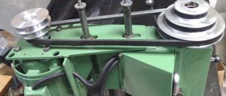
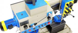
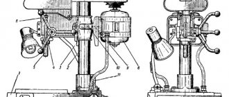
Photo of vertical drilling machine 2N118
Photo of vertical drilling machine 2n118
Photo of vertical drilling machine 2n118
Photo of a vertical drilling machine 2n118. Feed and spindle control
General view and controls of the drilling machine 2N118
Drilling machine controls 2n118
Specification of controls for drilling machine 2N118
- light switch
- coolant pump switch
- input circuit breaker
- feed mechanism control handle
- mechanical feed button
- feed shift knob
- push-button station “Right”, “Left”, “Stop”
- gear shift knob
- drill head clamp handle
- bolts for adjusting the wedge of the drill head
- table clamp handle
- bolts for adjusting the table wedge
- table lift handle
- square roller of the drill head lifting mechanism
- work cycle adjustment cams
- 3/4″ hole for connecting the machine to the electrical network
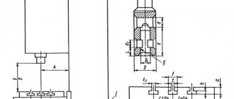
General view of the most common universal single-spindle vertical drilling machine 2N118
A box-shaped column is mounted on the foundation slab. In its upper part there is a spindle head that carries an electric motor and a spindle with a tool. A spindle head is installed on the vertical guides of the column, inside of which there is a feed mechanism that carries out the vertical movement of the spindle. The spindle can be raised and lowered mechanically or manually using the steering wheel. There is a table for installing and securing the device with the workpieces being processed. It can be installed at different heights, depending on the size of the workpiece.
Kinematic diagram and equipment design
The supporting element of a vertical drilling machine of this model, equipped with a single-spindle head, is a massive box-shaped column mounted on a base plate. The headstock of the device is mounted in the upper part of the column, which can move along its guides. On the headstock there is the main electric motor of a vertical drilling machine, and on its lower part there is a spindle assembly with a working head in which the cutting tool is fixed.
Machine spindle head - front view
In the inner part of the spindle head there is a gearbox, which is responsible for adjusting the rotation speed of the drilling head, as well as ensuring the movement of the latter in the vertical direction. A rack and pinion mechanism, present in the kinematic diagram of the headstock, is responsible for raising and lowering the working head of the machine, and the body by which this mechanism is activated is a special steering wheel.
Before processing, the part is fixed on the surface of the work table, which also has the ability to move along the column guides. The height of its location, which is chosen depending on the dimensions of the workpiece, is changed using a rotating handle located on the front side of the unit.
Height-adjustable machine work table
The elements included in the kinematic diagram of the vertical drilling machine under consideration function as follows.
- The gearbox, due to the presence of several shafts and a number of gears in its design, allows you to adjust the speed of rotation of the drilling head in 9 steps. The output shaft of the gearbox, which is connected to the spindle assembly of the machine using a spline connection, is made in the form of a hollow sleeve. By reversing the drive motor, you can change the direction of rotation of the working head of the equipment, which is necessary if an internal thread is being cut in the workpiece.
- The spindle feed in the vertical direction, as mentioned above, is carried out by a rack mounted in the equipment quill and a gear engaged with it installed in the spindle head. The machine’s feed box, which contains several gears, allows you to adjust the vertical movement of the spindle assembly in 6 steps.
- Both the gearbox and the feedbox are installed in the spindle head of the vertical drilling machine, which can also move vertically along the column guides. A corresponding handle is responsible for this movement, carried out through a rack and worm connection.
- Vertical movement of the worktable, triggered by rotation of the corresponding handle, is provided by a conical and screw pair, which are equipped with the kinematic diagram of this structural element of the machine.
Kinematic diagram of a vertical drilling machine 2N118
The elements by which the operation of a vertical drilling machine of this model is controlled include:
- automatic type input switch;
- work area lighting switch;
- a switch for starting and stopping the coolant pump;
- handle responsible for controlling the feed mechanism;
- a button that turns on the feed mechanism;
- handle for selecting feed parameters;
- a push-button station on which the “Left”, “Right”, “Stop” buttons are mounted;
- a handle responsible for selecting the required rotation speed of the drilling head;
- a handle that provides clamping of the drill head;
- bolts with which the wedge of the drilling head is adjusted;
- bolts for adjusting the wedge of the work table;
- a handle used to clamp the desktop;
- a handle responsible for lifting the desktop along the column guides;
- a square end of the roller, through which the mechanism for lifting the drilling head is activated;
- cams, with the help of which the equipment operating cycles are configured;
- hole (3/4 inch) in which electrical contacts are located for connecting equipment to the power supply.
Specifics of machine components and controls
Kinematic diagram of the drilling machine 2N118
Kinematic diagram of the drilling machine 2n118
Kinematic diagram of a vertical drilling machine 2N118 . The spindle speed is changed using a gearbox. The receiving shaft I rotates from the electric motor 38 through gear 1-2. The movement of shaft II is transmitted by one of three pairs of gears 3 - 4, 5 - 6 and 7 - 8. Further rotation is transmitted by one of the kinematic chains 9 - 10, 8 - 11 or 12 - 13. The final shaft of the gearbox III is a hollow sleeve, the spline hole of which transmits rotation to spindle IV. As a result, the spindle has nine different rotation speeds ranging from 177 to 2840 rpm. Reversing the spindle, necessary for thread-cutting operations, is carried out by reversing the electric motor.
The spindle work program is carried out using a rack and pinion transmission. The rack wheel 29 is engaged with the rack of the quill 30. When the wheel rotates, the quill moves vertically along with the spindle. The machine has six different feeds, carried out from the spindle through cylindrical gears 14 - 15 and a feed box. Rotation is transmitted to shaft VI by one of three gears 16 - 17, 18 - 19, 20 - 21, and then to shaft VII by one of two gears 22 - 23 or 21 - 24. The gear 25 - 26 and the worm pair 27 - 28 impart rotation to the rack and pinion wheel 29.
The speed and feed box, spindle and feed mechanism are mounted inside the drilling head, which can move along the column when the corresponding handle is rotated through 31-32 worm and 33-34 rack pairs. Vertical movement of the table is also done manually by turning the handle through a conical 36 - 35 and a screw 37 pair.
Technical data about the product
Technical characteristics, diagrams and operation of the 6р12 milling machine
Technical characteristics:
- “T” is a shaped working surface and is equal to 32.0 × 36.0 cm.
- The movement of the surface when the flywheel rotates is 2.4 mm, along the vertical plane - 35.0 cm.
- The total weight of the device is 450 kg.
- The distance from the extreme point of the spindle to the working surface is 65.0 cm.
- The machine's reach is 20.0 cm.
- The spindle head can move up to 30.0 cm.
- The working stroke of the sleeve is 15.0 cm.
- The spindle head moves 4.4 mm per revolution.
- The (average) spindle speed is 2.4 rpm, minimum 200 rpm, maximum 2.8 thousand rpm.
- The spindle rotation speed is adjusted according to nine parameters.
- The electric motor shaft power is one and a half kilowatts, the maximum rotation speed is 1.42 rpm.
- The maximum feed rate is 560 kgf.
- Dimensions 87.0x59.0x208.0 cm.
Among the main features is the spindle braking option.
https://youtube.com/watch?v=fW9omcEBioo
Description of the design of the drilling machine 2N118
Gearbox
The gearbox is designed to drive the machine spindle into rotation, as well as to change the frequency of its rotation (Fig. 7.5). The gearbox, through two gears 3 and 7, communicates to the spindle nine different rotation speed intervals. The gearbox shaft supports are placed in two plates: the top 5 and the bottom 8, which are tied together by three ties 4. The gearbox mechanisms are driven into rotation by a vertically located electric motor through a gear 6. The last gearbox shaft 2 is a hollow sleeve, splined hole which transmits rotation to the spindle. Gear 1 of the feed drive is attached to the same sleeve. The gearbox gears are switched from one handle, which has three positions around the circumference and three positions along the axis.
Gearbox
The feed box is a three-shaft mechanism mounted in a separate cast housing (Fig. 7.6). Six feeds are provided by gears 5 and 10.
The feed drive is carried out from a gear sitting on the spindle sleeve through gear 6. The third shaft of the feed box 9 is a hollow sleeve, inside of which passes shaft 8. This shaft, through clutch 7, transmits rotation to the worm of the feed mechanism through gear 1. Clutch 7 is used to turning on the mechanical feed when the specified processing depth is reached. In this case, the cam on the limb moves the rod vertically upward through a horizontal roller and, overcoming the resistance of the spring, disengages the clutch. Shaft 4, through pin 3, rotates the gear pump for lubrication.
The feed gears are switched by one handle, which has two axial positions and three circumferential positions. The handle is located on the front surface of the drilling head. The designs of the feed and speed switching mechanisms are identical.
The feedbox mechanisms are lubricated by gear pump 2, which also lubricates all other mechanisms. The feedbox mechanisms are assembled separately and the fully assembled unit is mounted in the drilling head.
Drill head
Drilling head of drilling machine 2n118
The drilling head (Fig. 7.7) consists of a box-section cast iron in which all the main components of the machine are mounted: speed box, feed box, spindle and feed mechanism. The first three units are assembled separately and are only attached to the drilling head.
The feed mechanism, consisting of a worm gear, a horizontal shaft 3, a dial 7 with associated parts, a handle 10, a cam 14 and an overrunning clutch 16, is an integral part of the drilling head assembly.
The feed mechanism is driven from the feed box through a pair of gears and is designed to perform the following functions:
- manual approach of the tool to the workpiece;
- turning on the working feed;
- manual feed advance;
- turning off the working feed;
- manual spindle retraction;
- manual feed is usually used when cutting threads.
The operating principle of the feed mechanism is as follows: when the handle 10 rotates, the cam clutch 14 turns toward itself, which rotates the shaft 3 through the overrunning clutch 16. The spindle is manually approached.
When the tool approaches the workpiece, the torque on shaft 3 increases, which cannot be transmitted by the teeth of the cam clutch, and the hub moves to the left along the shaft until the ends of the cam clutch 14 and the overrunning clutch 16 are opposite each other.
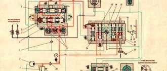
Electrical equipment and electrical circuit of the drilling machine 2N118
Electrical diagram of drilling machine 2n118
The electrical equipment of the machine contains:
- spindle rotation electric motor 1M;
- electric cooling pump 2M;
- start-up and automation equipment;
- selenium rectifier SV;
- local lighting.
Control of drilling machine 2N118
The following controls are installed on the machine:
- control buttons - “Left”, “Right” and “Stop”;
- introductory machine;
- manual starter for turning on the cooling pump with “Start” and “Stop” buttons.
Braking the spindle of the machine 2N118
The machine uses a dynamic braking circuit with direct current supplied to three phases of the stator winding through the contacts of the SC brake starter from a selenium rectifier SV, which is powered by a step-down transformer TBS2-01. Simultaneously with the supply of DC current during braking, the stator winding is short-circuited in two phases for better braking efficiency. Braking occurs only when the ZKU or 2VK button is pressed.
Operation of the electrical circuit of the 2N118 machine
By pressing the 1KU “Right” button, the K1 starter is turned on, which is self-blocking with block contacts 6-7, and with contacts 4-16 it turns on the intermediate relay RP, which with its contacts 4-16 will become self-powered, and with contacts 14-9 it prepares the switching on of the K2 starter, if During operation on the machine, spindle rotation is reversed by pressing 1VK.
By pressing the 2KU “Left” button, the K2 starter is turned on, which is self-blocking with block contacts 4-9.
Whenever the spindle rotates to the right, left, pressing the “Stop” button, braking is performed, and K1 and RP are turned off if there was a rotation to the right, or K2 if the rotation was to the left. Through contacts 13, 17, 18, the short-circuit braking starter will turn on, which supplies direct current to the stator winding of the electric motor, and the engine will brake.
Protection
The electric motor is protected from overloads and short circuits by an AST-3 automatic switch. Zero protection is provided by a coil of magnetic starters.
The machine must be grounded in accordance with existing rules and regulations.
2N118 single-spindle universal vertical drilling machine. Video.
The post-war rapid growth of industrial production in the USSR required an urgent expansion of the machine park. To prevent the outflow of currency abroad, domestic design bureaus began developing metal-cutting equipment. First, a basic model was produced, which was tested in real conditions. After this, the mechanism was improved. Such a modified unit is the 2N118 vertical drilling machine.
Drilling equipment
It is used in any technological chain, but its main purpose is small-scale and single-piece production. Such machines perform a number of operations:
- thread cutting;
- countersinking;
- drilling;
- trimming ends;
- deployment;
- countersinking.
After reviewing, they can be divided into three large groups depending on the operations performed:
- specialized, perform a limited number of actions;
- universal, make up the main part;
- special, they work without readjustment, according to a given cycle.
Such units can be classified according to the maximum drill diameter used:
- lightweight, drilling up to 12 mm;
- medium, obtaining holes 18-50 mm;
- heavy, drilling 75 mm holes.
The main distinctive features of metal-cutting equipment are the movements made by the cutting tool and devices. In our case, this is the rotation of the drill and the progressive feed of the spindle. All main parameters are included in the machine passport, which is directly included in the operating manual.
In this document you can find instructions for attaching the machine to the workplace. First of all, it must be located strictly horizontally in relation to the foundation. The reliability of all mechanisms depends on this. This is achieved using special levels.
The design of the machine assumes the following types:
- desktop;
- columned;
- radial drilling;
- deep drilling;
- multi-spindle;
- central;
- drilling and milling;
- coordinate drilling;
- radial drilling.
All of them are complex mechanisms, so before starting work, maintenance personnel must carefully read the operating instructions. And while working, adhere to all recommendations.
Brief information about machine grading
Classification of units:
- Machining of small holes up to 16.0 mm. Most often, such diameters are used in instrument making.
- Processing of medium and large diameters from 18.0 to 75.0 mm.
- Radial drill type for drilling large products.
- Machines for drilling high-precision diameters.
- Milling type.
- Centering machines.
- Multi-spindle machines.
Multi-spindle machine