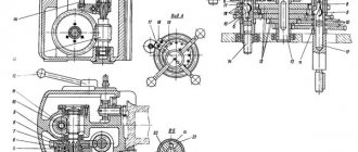
Description of the kinematic diagram of the 6B75 universal milling machine
The machine is driven by an A41-4 type electric motor with a power of N = 1.7 kW and a speed of n = 1420 rpm.
The movement from the electric motor is transmitted via a V-belt transmission to the receiving shaft of the gearbox.
From here the movement is transmitted in two directions:
- on horizontal and vertical spindles
- to the feed box and then to the caliper and horizontal slide
Different rotation speeds of the horizontal and vertical spindles are obtained with the following gearbox gear positions:
- I. 4—5—7—2—1—8—9—16 — 95 rpm
- II. 3—6—7—2—1—8—9—16 — 170 rpm
- III. 1—8—9—16 (gear clutches 2—3 are meshed) — 300 rpm
- IV. 4—5—8—9—16 (gear clutches 7—8 are meshed) — 470 rpm
- V. 3—6—8—9—16 (gear couplings 7—8 are meshed) - 900 rpm
- VI. 2—7—8—9—16 (gear clutches 7—8 and 2—3 are meshed) — 1650 rpm
Rotation is transmitted to the vertical spindle from gear 16 of the horizontal spindle through gears (15, 14, 13).
Consequently, the vertical spindle also has six different speeds (listed in “Machine Mechanics”).
From the drive sprocket 47, sitting on the receiving shaft of the gearbox, the movement is transmitted using a bushing-roller chain to the driven sprocket 46, sitting on the receiving shaft of the feedbox.
Various feeds transmitted to the caliper and horizontal slides are obtained with the following positions of the feed gears:
For horizontal slides:
- I. 45—43—44—40—42—37—35—34—33—32—20—19 (18) — 17.5 mm/min
- II. 45—43—44—40—41—36—35—34—33—32—20—19(18) — 26.8 mm/min
- III. 45—43—44—40—39—38—35—34—33—32—20—19 (18) — 44.7 mm/min
- IV. 45—43—42—37—35—34—33—32—20—19(18) — 69.7 mm/min
- V. 45—43—42—41—36—35—34—33—32—20—19(18) — 106.9 mm/min
- VI. 45—43—42—39—38—35—34—33—32—20—19 (18) — 178 mm/min
Note: When gear 18 is turned on, the feed direction changes.
To the caliper
From the drive shaft, on which gear 32 sits on a key, and further through the gears (27-26) to the lead screw 29. (In this case, the gear half-coupling 27 is engaged with the coupling half 48).
When the caliper moves in the opposite direction, the movement from the drive roller is transmitted through the gears—(23—22—21) to the lead screw 29 (in this case, the gear half-coupling 23 is engaged with the coupling half 49).
The amount of caliper feed is indicated in the “Feed Mechanism” section. Manual feeding of the horizontal slide is carried out using handwheels 50, and in the support - using handwheel 51.
The horizontal spindle headstock is moved using handwheel 52.
The movement of the quill of the vertical spindle in the body of the vertical head is carried out with a special key, which is placed on the square 53 of the pinion roller, and the latter engages with a rack cut into quills.
The feed mechanism is protected from damage by a ball-type safety device (gear clutch 34 and clutch 54).
The safety device is adjusted using nut 55.
Electrical diagram of the machine
The electrical circuit includes a whole set of special equipment and parts that control the operation of the machine. The order of operation of electrical equipment is as follows:
- After the input explosive is turned on, three-phase voltage is supplied to all operating circuits and control elements.
- Immediately after pressing the “Start” button (KU1), single-phase power is supplied to the starter “K”; in this case, its contacts close and turn on the main motor D1 and pump D2.
- When you press the red “Stop” button (KU), the starter’s power circuit is broken, after which the electric motors are turned off.
Please note: If it is necessary to stop the electric coolant supply pump, this can be done with a separate HV bag. Feed reversal is carried out using a drum-type switch ПШ, and local lighting is turned off using a MO switch
To protect electric motors from overloads, thermal relays are installed in three-phase power supply circuits
Feed reversal is carried out using a drum-type switch ПШ, and local lighting is turned off using a MO switch. To protect electric motors from overloads, thermal relays are installed in three-phase power supply circuits.
Technical characteristics of the 6B75 milling machine
| Parameter name | 6E75PF1 | 675P | 6B75 |
| Basic machine parameters | |||
| Accuracy class according to GOST 8-82 | P | P | N |
| Dimensions of horizontal (corner) table, mm | 200 x 630 | 200 x 630 | 200 x 630 |
| Vertical table dimensions, mm | 200 x 500 | 200 x 500 | 195 x 550 |
| Maximum weight of the workpiece, kg | 200 | ||
| The largest dimensions of the part processed with one installation (length x width x height), kg | 300 x 230 x 280 | ||
| Distance from the axis of the horizontal spindle to the working surface of the horizontal table, mm | 90..390 | 80..380 | 70..360 |
| Distance from the end of the vertical spindle to the working surface of the horizontal table, mm | 0..290 | 0..300 | 22..312 |
| Maximum overhang of the vertical spindle axis, mm | 130..330 | ||
| Maximum longitudinal stroke of the table (X), mm | 320 | 320 | 250 |
| Maximum vertical travel of the table (Z), mm | 290 | 300 | 290 |
| The largest transverse stroke of the spindle head (Y), mm | 200 | 200 | 150 |
| Limb division price, mm | 0,05 | 0,025 | |
| Horizontal and vertical machine spindles | |||
| Horizontal spindle rotation speed, rpm | 40..2000 | 50..1600 | 95..1650 |
| Vertical spindle rotation speed, rpm | 40..2000 | 63..2000 | 110..1860 |
| Number of spindle speeds | 18 | 16 | 6 |
| Maximum permissible torque on a horizontal spindle, Nm | 214 | ||
| Maximum permissible torque on a vertical spindle, Nm | 155 | ||
| Maximum axial movement of the vertical spindle, mm | 60 | 60 | |
| Maximum angle of rotation of the vertical head in the vertical plane, degree | ±90° | ±90° | ±45° |
| Taper of horizontal and vertical spindles | 40AT5 | Morse 4 | Morse 4 |
| Table | |||
| Limits of longitudinal and vertical table feeds (X, Z), mm/min | 10..1000 | 12,5..400 | 17,5..178 |
| Accelerated table speed, mm/min | 1800 | 935 | No |
| Number of table feeds | B/s | 16 | 6 |
| Maximum table feed force, N | 4000 | 5000 | |
| Headstock | |||
| Limits of spindle head cross feeds (Y), mm/min | 10..1000 | 12,5..400 | No |
| Number of spindle head feeds | B/s | 16 | – |
| Maximum feed force of the spindle head, N | 4000 | 5000 | |
| Accelerated speed of the spindle head, mm/min | 1800 | ||
| Electrical equipment and machine drive | |||
| Number of electric motors on the machine | 4 | 2 | |
| Main drive electric motor, kW | 1,5 | 1,5 | 1,7 |
| Feed drive electric motor, kW | 1,1 | No | |
| Hydraulic pump electric motor, kW | 0,06 | No | |
| Cooling pump drive electric motor, kW | 0,12 | 0,12 | 0,12 |
| Total power of electric motors, kW | 2,78 | 1,62 | 1,82 |
| Dimensions and weight of the machine | |||
| Machine dimensions (length x width x height), mm | 1350 x 1400 x 1750 | 1110 x 1170 x 1650 | 1150 x 1100 x 1600 |
| Machine weight, kg | 810 | 1100 | 855 |
Bibliography:
Operation and maintenance manual for universal milling machines 6V75 and 6V75P, 1966
Avrutin S.V. Fundamentals of Milling, 1962
Avrutin S.V. Milling, 1963
Acherkan N.S. Metal-cutting machines, Volume 1, 1965
Barbashov F.A. Milling business 1973, p.141
Barbashov F.A. Milling work (Vocational education), 1986
Blumberg V.A. Milling machine handbook, 1984
Grigoriev S.P. Practice of coordinate boring and milling work, 1980
Kopylov R.B. Working on milling machines, 1971
Kosovsky V.L. Handbook of a young milling operator, 1992, p. 180
Kuvshinsky V.V. Milling, 1977
Nichkov A.G. Milling machines (Machinist's Library), 1977
Pikus M.Yu. A mechanic's guide to repairing metal-cutting machines, 1987
Plotitsyn V.G. Calculations of settings and adjustments of milling machines, 1969
Plotitsyn V.G. Setting up milling machines, 1975
Ryabov S.A. Modern milling machines and their equipment, 2006
Skhirtladze A.G., Novikov V.Yu. Technological equipment for machine-building industries, 1980
Tepinkichiev V.K. Metal cutting machines, 1973
Chernov N.N. Metal cutting machines, 1988
Frenkel S.Sh. Handbook of a young milling operator (3rd ed.) (Vocational education), 1978
Related Links. Additional Information
Home About the company News Articles Price list Contacts Reference information Download passport Interesting video KPO woodworking machines Manufacturers
Main characteristics of the machine
When familiarizing yourself with the machine, a number of its spatial characteristics stand out, which are discussed below.
Overall dimensions of the working space and connecting bases
The vertically located surface of the main work table has a size of 200x500 mm. Other characteristic parameters of the machine (including attached elements) are given below:
- For a corner table, initially located horizontally, the surface size is 200x630 mm.
- The distance between the corner table surface and the spindle axis ranges from 55 to 355 mm.
- The same size for a vertically oriented spindle assembly can vary from 0 to 280 mm.
- The maximum permissible table travel along the longitudinal axis (X) is about 320 mm.
- Its maximum vertical stroke (Z) is at least 300 mm.
- The maximum permissible stroke of the router (transverse Y) is about 200 mm.
With such overall and spatial parameters, the weight of the machine does not exceed 635 kg.
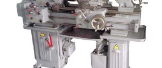
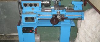
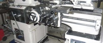
General view of the wide-universal milling machine 675
Structurally, model 675 machines consist of a frame on which a work table and a spindle head are mounted. To fix the workpiece, you can use the main horizontal surface. Thanks to the rotating function of the working head, processing can be performed at an angle.
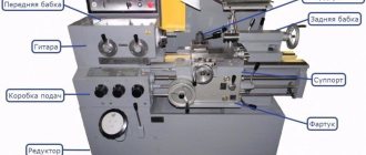
Location of components
The main parts of the machine are located according to the figure on the left. A well-chosen layout of controls and other parts of the equipment ensures convenient operation.
List of components
In addition to the main table, equipment components include:
- a head placed vertically;
- spindle tool head (horizontal);
- box for switching and adjusting operating speeds and feeds (KS);
- a table capable of being positioned at an angle to the main plane;
- support, as well as the bed.
The design of a milling unit also includes its set of electrical equipment.
Important! To increase functionality when purchasing it, you can order additional units.
These include, in particular, an attachment for hammering parts, which is not included in the kit.
Location of controls for the 675 milling machine
The location of the controls is shown in the figure on the right. Each of the positions is designated by its own number, the explanation of which is given in the next section.
Description of the kinematic diagram of the 6B75 universal milling machine
The machine is driven by an A41-4 type electric motor with a power of N = 1.7 kW and a speed of n = 1420 rpm.
The movement from the electric motor is transmitted via a V-belt transmission to the receiving shaft of the gearbox.
From here the movement is transmitted in two directions:
- on horizontal and vertical spindles
- to the feed box and then to the caliper and horizontal slide
Different rotation speeds of the horizontal and vertical spindles are obtained with the following gearbox gear positions:
- I. 4—5—7—2—1—8—9—16 – 95 rpm
- II. 3—6—7—2—1—8—9—16 – 170 rpm
- III. 1—8—9—16 (gear clutches 2—3 are meshed) – 300 rpm
- IV. 4—5—8—9—16 (gear clutches 7—8 are meshed) – 470 rpm
- V. 3—6—8—9—16 (gear couplings 7—8 are meshed) – 900 rpm
- VI. 2—7—8—9—16 (gear clutches 7—8 and 2—3 are meshed) – 1650 rpm
Rotation is transmitted to the vertical spindle from gear 16 of the horizontal spindle through gears (15, 14, 13).
Consequently, the vertical spindle also has six different speeds (listed in “Machine Mechanics”).
From the drive sprocket 47, sitting on the receiving shaft of the gearbox, the movement is transmitted using a bushing-roller chain to the driven sprocket 46, sitting on the receiving shaft of the feedbox.
Various feeds transmitted to the caliper and horizontal slides are obtained with the following positions of the feed gears:
For horizontal slides:
- I. 45—43—44—40—42—37—35—34—33—32—20—19 (18) – 17.5 mm/min
- II. 45—43—44—40—41—36—35—34—33—32—20—19(18) – 26.8 mm/min
- III. 45—43—44—40—39—38—35—34—33—32—20—19(18) – 44.7 mm/min
- IV. 45—43—42—37—35—34—33—32—20—19(18) – 69.7 mm/min
- V. 45—43—42—41—36—35—34—33—32—20—19(18) – 106.9 mm/min
- VI. 45—43—42—39—38—35—34—33—32—20—19(18) – 178 mm/min
Note: When gear 18 is turned on, the feed direction changes.
To the caliper
From the drive shaft, on which gear 32 sits on a key, and further through the gears (27-26) to the lead screw 29. (In this case, the gear half-coupling 27 is engaged with the coupling half 48).
When the caliper moves in the opposite direction, the movement from the drive roller is transmitted through the gears—(23—22—21) to the lead screw 29 (in this case, the gear half-coupling 23 is engaged with the coupling half 49).
The amount of caliper feed is indicated in the “Feed Mechanism” section. Manual feeding of the horizontal slide is carried out using handwheels 50, and in the support - using handwheel 51.
The horizontal spindle headstock is moved using handwheel 52.
The movement of the quill of the vertical spindle in the body of the vertical head is carried out with a special key, which is placed on the square 53 of the pinion roller, and the latter engages with a rack cut into quills.
The feed mechanism is protected from damage by a ball-type safety device (gear clutch 34 and clutch 54).
The safety device is adjusted using nut 55.
Description of individual components and accessories
When describing the composition of the Model 675 machines, the following working units can be distinguished.
Functional cantilever milling machine 6t80sh: description of the main components, characteristics
bed
This is the base of the machine on which all other working units are located. Controls for milling and drilling modes, as well as turning the device on and off are also located here.
Caliper
This unit ensures the supply of the workpiece through lead screws 1 and 8, as well as the main drive shaft 24. Its direction is changed using the cross handle (position 16).
In extreme positions in all planes of movement of the caliper, its supply is turned off due to special stops with limit switches 6 and 15.
Horizontal spindle
The horizontal position of the spindle is its main operating state, in which milling operations are carried out on parts fixed on an angular inclined table. It is mounted on the frame on the right and is controlled by a separate rotating feed handle.
Vertical spindle
The vertical head is a removable unit, when installed, the equipment can be easily adjusted to another operating mode. It is fixed to the headstock using two bolts coaxially with the second spindle. The head, placed vertically, can be rotated 90° on both sides, for which purpose there are markings on the body flange in the form of divisions in degrees.
Corner universal table
The plane of the horizontal universal table has a built-in tilt adjustment mechanism, which ensures the convenience of processing workpieces mounted on it.
Round table
The rotary round table is located in the center of the bed; it is needed to fix workpieces processed using a tool fixed in the spindle.
Parallel vice
Special parallel vices are used to clamp the workpiece in the main work table. Their presence significantly simplifies the fixation of workpieces before processing and increases the productivity of operations.
Dividing head
A special dividing or impact head is not included in the standard configuration of this piece of equipment. It is usually purchased separately and installed on a vertical spindle. It is used when it is necessary to cut various grooves and splines on metal workpieces or for sawing.
675p characteristics
The technical characteristics of the 675p machine allow you to mill products in a horizontal and vertical plane, as well as process parts at an angle. The machine is equipped with a corner table with a horizontal working plane and a main table with a vertical working plane.
| Characteristic name | Unit change | Options |
| Distance from the axis of the horizontal spindle to the working surface of the corner horizontal table | mm | 80…380 |
| Distance from the end of the vertical spindle to the working surface of the corner horizontal table | mm | 0…300 |
| Distance from the end of the bed to the axis of the vertical spindle | mm | 130…330 |
| The distance from the end of the horizontal spindle to the end of the shackle, maximum | mm | 210 |
| Maximum table movement | ||
| Longitudinal | mm | 320 |
| Vertical | mm | 300 |
| The price of one division of the dial | mm | 0,05 |
| Moving the dial one revolution | mm | |
| Longitudinal | mm | 5 |
| Vertical | mm | 2,5 |
| Dimensions of the working surface of the table (L x W) | mm | 500 x 200 |
| Number of T-slots | 2 | |
| T-slot width | mm | 14 |
| Distance between T-slots | mm | 100 |
| Dimensions of the working surface of the table (L x W) | mm | 630 x 200 |
| Number of T-slots | 3 | |
| T-slot width | mm | 14 |
| Distance between T-slots | mm | 50 |
| Maximum displacement | mm | 200 |
| Switching stops | There is | |
| The price of one division of the dial | mm | 0,05 |
| Moving the dial one revolution | mm | 5 |
| Inner cone | Morse No. 4 | |
| Maximum rotation angle | hail | ±90 |
| Maximum spindle movement (by hand) | mm | 60 |
| Inner cone | Morse 4 | |
| Main drive of the machine | ||
| Speed | rpm | 1420 |
| Power | kW | 1,5 |
| Electric coolant pump | ||
| Speed | rpm | 2800 |
| Power | kW | 0,12 |
| Overall dimensions of the machine | ||
| length | mm | 1110 |
| width | mm | 1170 |
| height | mm | 1650 |
| Machine weight | kg | 770 |
Technological characteristics
Technical characteristics of the milling machine model 675P:
- machine dimensions 1.11x1.17x1.65 m;
- unit weight 1.1 t;
- electric motor power – 1.5 kW;
- the power of the electric motor installed on the cooling pump is 0.12 kW;
- dimensions of working panels – horizontally located 0.2x0.63 m, vertical 0.2x0.5 m;
- equipment accuracy class – P;
- the distance from the center of the spindle assembly in a horizontal block is 8-38 cm to the working panel, in a vertical block - 0-30 cm;
- the maximum reach of the spindle, which is placed horizontally, is 13-33 cm;
- maximum possible displacement - along the X axis 32 cm, along the Y axis 20 cm, along the Z axis 30 cm;
- spindle rotation speed – horizontally located 50-6000 rpm, vertical 63-2000 rpm;
- the maximum possible torque is horizontal 214 Nm, vertical 155 Nm.
Considering all the listed characteristics of this equipment, it is clear why it has gained such popularity. This unit is characterized by high power, which ensures sufficient labor productivity when processing various parts.
Passport for tool milling machine 675P | CASSPORTIZATION
Purpose of the technical device.
The 675P instrument wide-universal high-precision milling machine is designed to perform a variety of milling work with a horizontal or vertical spindle, which, if necessary, can be rotated at an angle. The workpiece can be mounted on a main table with a vertical work plane or on a corner table with a horizontal work plane.
Specifications.
Distance from the axis of the horizontal spindle to the working surface of the corner horizontal table, mm – 80-380 Distance from the end of the vertical spindle to the working surface of the corner horizontal table, mm – 0-300 Distance from the end of the frame to the axis of the vertical spindle, mm -130-330 Distance from end of the horizontal spindle to the end of the shackle (maximum), mm – 210 Dimensions of the machine, mm: length – 1110 width – 1170 height – 1650
Machine weight without accessories, kg – 770
tu-passport.ru
Passport of a universal machine
The passport begins with an indication of the brand of the machine and an indication of the manufacturer. Next, there is an image of the equipment in all projections, a description of the main components. All accessories and devices included in the equipment are listed with their functions. The document includes all diagrams, drawings of the main components and a list of wear parts. To transport the machine, the passport contains diagrams for slinging and installation on the foundation.
The passport of the milling machine can be downloaded for free from the link - Passport of the wide-universal milling machine SF 675.
Design Features
The 675 milling machine is characterized by its small size and the ability to process workpieces up to 600 mm long. The design includes two spindles, a working vertical table and a removable horizontal one. The machine kit includes a cabinet for accessories and tools.
Main movement chain
Rotation is transmitted to the horizontal spindle through gearing with a drum gear connected to the gearbox. The electric motor is connected to the drive shaft by a V-belt transmission. The vertical spindle rotates through a bevel gear connection with a horizontal motor. The speed of both working bodies is adjusted using one handle.
Feed chain
The feed chain transmits movement to 3 working units at once, ensuring movement along all axes:
- support – vertical;
- slide – longitudinal;
- spindle head – transverse.
The rapid stroke is 935 mm/min. 16 working feeds, from 12.5 mm/min to 400 mm/min. The feed mechanism operates from the main drive, receiving rotation from the gearbox through the toothing of the gears.
Caliper
Through the support, longitudinal and transverse movement of the table with the part is carried out through the lead screw and the drive shaft. The direction of movement in 3 directions is activated by one cross handle in the direction of movement. The parts are lubricated with a lubricator.
bed
The bed has a high base. On top there is a trunk used when working a horizontal spindle with cylindrical cutters. On the side of the frame body there is a box molded for the feed box. It closes with a door. In the front part there is a rack with console guides.
Horizontal spindle
The horizontal spindle is located in the upper part of the frame, under the trunk. It receives rotation from the gearbox through gearing. The spindle head is mounted on 2 radial supports and rests on 4 thrust bearings. To fasten parts in the spindle there is a Morse taper 4. When installing a mandrel with cutters, use an earring.
The trunk is moved manually. Clamped in working position on the right with 2 handles. The rotation speed is adjustable in steps and has 16 positions. The movement of the spindle head in the horizontal axis is limited by stops. Mineral oil lubrication is carried out by splashing. The liquid is supplied to the sump of the spindle head housing.
Vertical spindle
The vertical head is a removable unit. It is secured to the horizontal spindle head with two screws and receives rotation from it. Installation is carried out according to risks for the alignment of rotating parts. The trunk is retracted to the rearmost position.
The vertical spindle together with the head is rotated 90⁰ manually according to a scale marked on the base of its body and secured with pins. A spring built into the body balances the sleeve as it moves. Radial loads are absorbed by two supports. Axial vibrations are damped by thrust bearings.
Design and its features
All working units are mounted directly on the cast machine bed. The spindle does not change its position and only moves forward during operation.
Trunk and earrings
The trunk moves horizontally, parallel to the spindle, along guides located in the upper part of the frame. A motor is installed in the rear part of the trunk body. It turns on when installed in front of the rotary head and rotates the tool installed in it.
When processing massive parts, the mandrel with the tool is fixed with earrings. They move along guides at the bottom of the trunk.
Gearbox
The gearbox is located directly in the hollow frame of the machine, in its upper part. An elastic coupling connects the gearbox to the electric motor shaft and at the same time eliminates misalignment of rotating parts.
To carry out inspection and maintenance of the gearbox, there is a special door on the right side of the frame.
Gearbox
The shift box is located directly above the gearbox, in the trunk. With its help, the required cutting mode is set using the handles located on the right, on the trunk body.
Gearbox
The console houses the feed box. The handles on the front wall of the unit set all feeds for movement in any direction. The feed drive is independent, powered by a motor located directly in the console body.
6t12
An adjustable ball clutch is built into the feed box. It protects against overloads by disconnecting the box from the motor shaft.
Overall dimensions of the workspace
Overall space is determined by the following parameters:
- table dimensions 1250×320 mm;
- maximum longitudinal movement 800 mm and transverse 240 mm;
- distance from the spindle axis to the table surface is 30–450 mm;
- the distance from the axis of the rotating spindle head to the frame guides is 260–280 mm.
One division of the dial is equal to a displacement of 0.05 mm in any direction.
General layout of the wide-universal milling machine 67K25PF2
A multi-purpose tool CNC milling machine consists of separate assembly units. A rack is attached to a cast iron base, where all the main components of the machine are mounted. The milling head moves along the horizontal guides of the rack, to which are attached: a vertical head, a trunk, a gearbox and a control panel. The caliper moves along the vertical guides of the rack, and the slide moves along its horizontal guides.
The feed motor is attached to the bottom of the rack.
To expand the technological capabilities of the machine, a large number of accessories are attached to it.
A corner or universal table is attached to the vertical base plane of the slide, which is used for installing the workpieces.
For dividing work, a round table and a dividing head are used, which can be installed either on a corner table or on a vertical plane of a slide.
For slotting work, a slotting head is designed, which is mounted on the milling head.
The high-speed head has its own drive and is also attached to the milling head.
The tool is mounted in the cones of the spindles. The tool clamping in the milling and vertical heads is mechanized.
Gearbox
The gearbox is assembled in a special housing 4.
The body is attached with a flange to the end of the milling head, and with flange 9 the box fits into the centering hole of the head. The gearbox consists of four shafts and blocks of gears, the movement of which allows the spindle to provide eighteen different speeds. Speed switching is carried out by a switching mechanism.
To change the speed, gear shift knob 2 must be lowered down. In this case, discs 10 and 12 are moved apart under the action of spring II. When turning the speed dial 3 and the associated disks, the position of the disk holes relative to the fingers 13 changes, thereby preparing for changing speeds. Then, using shift handle 2, the discs are brought to their original position. Then the fingers 13, moving, using levers, will move the gearbox gear blocks. When switching, it is possible that the ends of the teeth of the meshed gears will coincide and the discs will not align. In this case, you need to press the “Push” button on the remote control.
When switching speeds (when retracting the disks), rotation automatically stops.
Cylinder 5, disc springs 6, pipe 7 and cleaning rod 8 are provided for mechanized clamping of the tool. Clamping is carried out by disc springs b, and pressing is carried out by hydraulic cylinder 5 when the hydraulics are turned on.
Milling head
The milling head (Fig. 6.6) is equipped with rectangular guides and moves along the horizontal guides of the rack. A horizontal spindle is mounted in the front part of the headstock, which is driven into rotation by a gearbox secured by a flange at the rear of the headstock. A bracket 2 is attached to the end of the headstock, in the lower part of which a lead screw 5 is fixed, which ensures the transverse movement of the headstock. The main drive with a motor 4 and a poly-V-ribbed transmission is attached to the bracket 2, which transmits rotation to the gearbox with a rigid coupling 3. The tension of the poly-V-belt 7 is adjusted by moving the housing 8 using a screw 9. The trunk I moves along the upper guides of the headstock with support 6, which serves for horizontal milling mandrels.
Spindle horizontal
Spindle I is mounted in the milling head housing and receives rotation from the gearbox. The front and rear spindle supports are a double-row roller bearing with a tapered hole 2 and 4. Axial loads are carried by thrust bearings 3.
Machine support
The support serves for longitudinal and vertical movement of the main table mechanically or manually. The mechanical feed of the table is carried out by lead screws I and 16, which receive rotation when the clutches are engaged, from the drive shaft 2. The table is moved manually from the flywheel 12, and the support from the flywheel II. Flywheel II is mounted in bracket 10, which rotates on axis 9 relative to the fixed bracket 8 and can be installed in a convenient working position.
The movement of the caliper is controlled by a ruler and a dial with a division value of 0.02 mm.
Rack
The stand 17 is installed on the base 12 and is a box-section casting on which the main components of the machine are located, connected to each other by kinematic links. At the rear lower part of the rack on the plate 15 there is a motor 14, the rotation from which is transmitted to the shaft 6 through a gear pair 13-16, shaft 7, coupling II and a conical pair 9-8. When the electromagnetic clutch 4 is turned on, through a conical pair 1-2 to the pipe 18 with nuts 19 and 20. Flywheel 21 is used to manually move the milling head.
Maintenance and repair work
The most important part of preventative repair work is maintenance. It consists of regularly inspecting the main components of the machine, checking their performance and lubrication.
Electrical equipment, like other machine components, gradually wears out both physically and mentally. But most machine components can be easily replaced with similar ones, which significantly extends the service life of the equipment and increases the operating parameters of the machine. During operation, the machine must be grounded and for normal operation it must be operated in a room with a humidity of 65% and a temperature of 20 °C.
Design and operation of milling machine 679
The kinematic diagram (Fig. 7) of the machine consists of the following circuits:
- A. main movement chain;
- b. feed chain
Main movement chain of milling machine 679
From an electric motor with a power of 2.8 kW, the movement is transmitted to shaft 1 by a V-belt drive. From shaft I, through the gearbox gears sitting on shafts II and III, gear 56 sitting on shaft IV, through gear 47, rotation is transmitted to the horizontal spindle V.
The vertical spindle VII receives rotation from shaft V through a conical pair 41.42, shaft VI and a cylindrical pair 43.44. Axial movement of the vertical spindle is carried out by the handle of the rack and pinion gear (46), which moves the sleeve with the rack (45) manually.
The different positions of the double gears of the gearbox (1-2; 3-4; 10-11) make it possible to impart eight different speeds (see table 1) to the horizontal spindle (from 110 to 1230 rpm) and eight speeds (see Table 2) vertical spindle (from 150 to 1660 rpm).
The numbers of revolutions given in Tables 1 and 2 constitute a standard series; Deviations of actual values of speed numbers from the standard range fluctuate within 5%.
Feed chain of milling machine 679
The machine feed drive is designed as follows.
Mechanical movements of the table are carried out by a feed mechanism, which receives rotation from shaft 1 of the gearbox through spur gears 12; 15; 16; 17 and feed box.
From shaft XI through chain transmission 58; 59 rotation is transmitted to shaft XII, conical pair 60; 61, vertical shaft XIII.
Gears 33; 34 transmits rotation to freely seated wheels 31 and 35, and through wheel 30 to gear wheels 29 and 32.
The longitudinal mechanical movement of the table is carried out by engaging the shaft coupling XV with the gear coupling 31 (moving to the left) - and with the wheel coupling 32 - (moving to the right). Through a conical pair 27; 28 rotation is imparted to the longitudinal stroke screw XVI.
Manual longitudinal movement of the table is carried out by two handles sitting on the ends of the screw XVI.
Vertical mechanical movement of the caliper with the table upward is carried out by engaging the clutch of screw XIV with the clutch of gear 29, and downwards - with the clutch of gear 35.
Manual vertical movement of the caliper is carried out by a handwheel sitting on shaft XVII through a conical pair 37; 36 and vertical screw XIV.
The transverse mechanical movement of the horizontal headstock, replacing the transverse movement of the table along the console usually accepted in milling machines, is carried out as follows: from the feedbox shaft XI through the chain drive 57; 53, rotation is transmitted to shaft XVIII, on which bevel gears 52, 54 sit freely.
By engaging the shaft coupling XVIII with the wheel coupling 54, rotation is transmitted to the cylindrical gear pair 50; 51 and nut 49. In this case, the horizontal headstock carrying the screw 48 moves forward (towards the work table). When the shaft coupling XVIII is engaged with the wheel coupling 52, the horizontal headstock is told to move in the opposite direction.
Manual movement of the horizontal headstock is carried out by a handwheel sitting on shaft XIX.
Depending on the switching of double gears 13-14; 18-19; 20-21 shaft XI can be given eight different speeds. As a result, we obtain eight longitudinal feeds (see Table 3), eight vertical feeds (see Table 4) and eight transverse feeds (see Table 5).
Feeds are expressed in standard series values. The deviation of the actual values of minute feeds from standard values fluctuates, as for spindle speeds, within 5%.
Machine 676. Universal milling machine. Manual
This instruction manual for the “Universal Milling Machine 676” contains information necessary both for the operating personnel of this machine and for the employee directly involved in working on this machine. This manual is an electronic version in PDF format of the original paper version. This documentation contains the Passport and Manual (instructions) for the operation of the universal milling machine 676
Purpose Unpacking and transportation Foundation, installation and installation Passport Specification of controls Specification of machine gears, screws and nuts Specification of gears and worm wheels, worms, screws and nuts accessories Main motion mechanics Calculation of spindle speeds Feed mechanics Calculation of feed rates Specification of bearings, rolling components Complete statement Brief description of the machine and accessories
- General layout
- Headstock
- Caliper
- Gearbox
- Gearbox
- Vertical spindle head
- Base and cooling
- Corner table
- Universal table
- Vise
Round table Slotting head Dividing head
- Guitar to dividing head
- High speed head
Electrical equipment of the machine
- Description of the electrical circuit
- Protection
Specification of purchased equipment Specification for the lubrication scheme of the machine Specification of lubrication points and elements of the lubrication system of accessories Instructions for servicing the lubrication system Preparing the machine for start-up Setting up the machine Installing the tool Setting the number of revolutions Setting the feed value Installing accessories Complex division Selection table of replacement gears for cutting spirals Adjusting the machine
- Gearbox
- Gearbox
- Caliper
- Headstock
- Base and cooling
- Vertical spindle head
- Round table
- Dividing head
Machine acceptance certificate Testing the machine for compliance with accuracy standards Accessories and tools for the machine General conclusion on testing the machine Additional comments
Advantages and disadvantages of equipment
The advantages of machines type 675P include:
- Good vibration absorption due to the massive cast iron bed, which guarantees high quality machining of parts.
- Wide range of sizes of processed parts (up to 80 cm in length and up to 25 cm in width).
- Expanded functionality (allows impact operations using the included head).
- Possibility of installation in tool shops and small workshops.
- Simple and intuitive controls.
- Extended range of rotation speeds of both spindles, which allows you to select the optimal processing mode.
The machine provides the possibility of using another spindle head mounted on a retractable trunk. This auxiliary unit is capable of rotating in both planes at angles of ±90 degrees.
The relative disadvantages of these models include insufficiently high reliability, as well as low productivity, which is why they are not suitable for large-scale production.
Features of modification 675P
The model of the wide-universal milling machine 675P is equipped with a tool cabinet. The machine has advantages over other units of the 675 series:
- increased processing accuracy;
- increased size of processed parts up to 250 mm in width and 800 mm in length;
- powerful pump with a supply of 22 liters of oil per minute;
- additional control panel on the side of the rack.
The small-sized machine can be installed in small workshops and garages.
Advantages and disadvantages of the model
The 675 milling cutter under consideration is characterized by quite a large number of advantages. They are as follows:
- The controls are very simple and intuitive.
- The design is characterized by relatively small dimensions. In addition, the low weight of the milling machine allows them to be installed in home workshops.
- The device has a wide rotation range, which allows you to choose the most suitable operating mode.
- There is an electric pump that supplies coolant to the milling site. Such a lubricant significantly reduces the temperature in the cutting zone.
- The device has a spindle head that rotates 90 degrees in two directions.
The disadvantages of this model are also significant. An example is the relatively low reliability, as well as a reduced performance indicator, due to which the model cannot be installed for the production of large series of products.
Corner universal table
The removable corner table is hung on the support using the upper dowels. Screwed to the work surface with bolts. It has 5 T-shaped slots for securing the workpiece and rotates it around a horizontal axis. The table rotates manually, along the dial on the front. The clamp handle of the device is also located there.
Vise
The vice is installed on the work table and rotary table. They allow processing small parts with high precision and making complex reliefs.
Round table
The removable accessories included with the machine include a round table. It is attached to the longitudinal table. Thanks to the dividing head, its functionality is increased. The side and top surfaces of the workpiece are processed using a horizontal spindle.
Dividing head
The dividing head allows you to rotate the part at a given angle with high accuracy. The device allows you to produce gears and other complex parts with repeating elements.
Purpose and scope
The equipment can be used for a range of milling and boring operations with high accuracy parameters for machining parts. The following operations can be performed on the machine: drilling, reaming, chiselling, centering, milling, boring, reaming, countersinking.
For machine-building enterprises and small-scale production, this machine is indispensable in the manufacture of parts, planes, and tools. Due to the multi-level feed system, the machine is characterized by economical and precise processing of workpieces.
Advantages and disadvantages of the model
The 675 milling cutter under consideration is characterized by quite a large number of advantages. They are as follows:
- The controls are very simple and intuitive.
- The design is characterized by relatively small dimensions. In addition, the low weight of the milling machine allows them to be installed in home workshops.
- The device has a wide rotation range, which allows you to choose the most suitable operating mode.
- There is an electric pump that supplies coolant to the milling site. Such a lubricant significantly reduces the temperature in the cutting zone.
- The device has a spindle head that rotates 90 degrees in two directions.
The disadvantages of this model are also significant. An example is the relatively low reliability, as well as a reduced performance indicator, due to which the model cannot be installed for the production of large series of products.
Passport of horizontal milling machine 6Т82Г (6Р82Г)
This instruction manual “Horizontal milling machine 6T82G (6R82G)” contains information necessary both for the operating personnel of this machine and for the employee directly involved in working on this machine. This manual is an electronic version in PDF format of the original paper version with some chapters missing.
Model 6P82 belongs to the class of horizontal milling machines with a horizontal placement of the spindle part. The manufacturer is the Gorky Milling Units Plant. It is capable of processing steel, cast iron products, as well as non-ferrous metals. Its versatility is characterized by the ability to work with finger, disk, end and end milling cutters. The machine can be used for individual purposes at home or for mass production.
Purpose and advantages of equipment
An important note is that throughout the entire operation the position of the spindle is unchanged and fixed in a horizontal state. But the work table can be positioned vertically, and relative to the spindle shaft perpendicular to the axis of rotation. This allows you to significantly expand the scope of the unit’s activities.
It is a 6P82 horizontal cantilever milling machine, since the basic configuration includes the presence of a console as a supporting element for moving the table horizontally. Many large metal fabrication companies use it in mass production. However, it is no less practical for carrying out individual work in factory or domestic conditions. For work, any cutters can be used for processing cast iron, steel products and blanks made of non-ferrous metals and alloys. It is actively used in automated production lines, as well as in conjunction with other types of equipment for carrying out work operations. The design of the model is thought out in such a way that during operation it ensures maximum operator safety and ease of operation.
Reviews
The widely-universal milling machine OF-55 has long gained popularity at enterprises in the mechanical engineering industry. This equipment, according to the owners, is distinguished by its reliability, wide functionality, as well as the accuracy and quality of processing workpieces made of ferrous and non-ferrous metal. Also, all owners note the classic version of controlling this machine, which allows even a beginner to quickly master it. The machine itself was made according to a German analogue, but has been in demand at domestic enterprises for more than 30 years and is one of the most reliable and proven equipment.
The highly versatile OF-55 machine is considered one of the most proven types of equipment. An increased class of accuracy and expanded functionality make it possible to perform a number of specific operations on such equipment, including chiselling.