Information about the manufacturer of the cantilever milling machine
6M12P machines were produced at GZFS. The Gorky Milling Machine Plant came into operation in 1931. It was built under the industrialization program. For its construction and equipment, a German design of machine tool factories was used. At that time it was the only enterprise in the country producing milling equipment.
The first machine was released in December 1931. Models of the 6M12P series began rolling off the assembly line in 1960. Now the Nizhny Novgorod plant is part of the RosStankom industrial group and produces milling machines, including CNC equipment.
Reference! In 1936, the company produced a unique 35-ton machine. It was specially developed and manufactured to process tubes for the Moscow metro.
Purpose and scope
The vertical milling console machine 6M12P has a frame of increased strength. It is designed to perform work:
- milling of horizontal and vertical planes;
- selection of grooves;
- corner processing;
- cutting gears;
- drilling;
- boring.
The machine processes workpieces made of cast iron, steel, and non-ferrous metal alloys. They make levers, strips, cushions, reamers, spirals and other parts, the manufacture of which requires continuous rotation.
Weight, dimensions and design
The 6M12P machine is distinguished by its rigid design, which allows it to produce complex parts with high precision - class H. Main dimensions of the unit:
- table 1250×320 mm;
- maximum workpiece weight 250 kg;
- dimensions 2395×1745×2000 mm;
- weight 3000 kg.
The greatest longitudinal movement of the table in mechanical mode is 700 mm.
The machine consists of standard components:
- base;
- bed;
- swivel head;
- console;
- sled and table;
- electrical equipment;
- gearbox;
- gearbox;
- switch box;
- gearbox.
The drive motor is mounted on a stand at the rear. The gearbox is in a hollow housing.
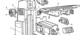
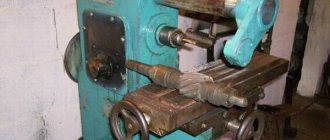
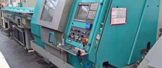
Location of controls for the 6M12P cantilever milling machine
Technical characteristics and design features of the IZH-250 lathe
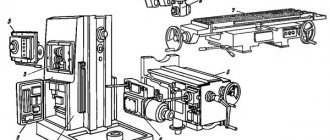
Location of controls for the 6M12P cantilever milling machine
Location of controls for the 6M12P cantilever milling machine
Location of controls for the 6M12P cantilever milling machine
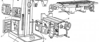
List of components of the 6M12P cantilever milling machine
- bed
- Swivel head
- Gearbox
- Gearbox
- Switch box
- Console
- Table and slide
- Electrical equipment
List of controls for the 6M12P cantilever milling machine
- Cooling intensity control valve
- Handwheel for manual longitudinal movement of the table
- Cams for limiting the longitudinal travel of the table in extreme positions or reversing the table in semi-automatic and automatic cycles
- Cams for switching the table from feed to high speed or from high speed to feed
- Switch for automatic cycle or manual control of the machine
- Spindle start button
- Stop button
- "Quick" button
- Table lubrication hand pump handle
- Handle for switching on vertical or transverse table feed
- Console clamp handle on bed guides
- Handwheel for manual transverse movement of the table
- Slide clamp handle on console guides
- Table control switch: automatic cycle - manual control - round table operation
- Hexagon rotation of milling head
- Table Clamp Screws on the Slide
- Spindle sleeve movement flywheel
- Light switch "On - Off"
- Stop spindle button
- Spindle start button
- Handle and dial for switching spindle speeds
- Spindle pulse button
- "Quick table" button
- Input switch "On - Off"
- Cooling Pump On/Off Switch
- Spindle rotation direction switch “Left - Right”
- Control handle for longitudinal movement of the table
- Console lift handle
- Mushroom and dial for switching table feeds
- Table cross travel limiting cams
- Spindle sleeve clamp handle
- Cams for limiting the vertical movement of the table
- Feed shift mechanism locking button
- Rotary milling head clamp nuts
Specifications
Model 6M12P has technical characteristics:
- spindle speed 31.5–1600 rpm;
- drive power 7.5 kW;
- number of speeds 18;
- milling spindle hole 29 mm;
- table 1250×320 mm;
- spindle distance from table 30–400 mm;
- spindle cone No. 3 according to GOST 24644-81.
The machine has switching stops for all movements of the table and slide.
Bed and console
The bed has a trapezoidal shape and is rigid. Inside there is a gearbox and an electrical cabinet. The console moves vertically along rails at the front of the rack. It contains the feed box and all components associated with the longitudinal and transverse movement of the table. In the Z axis, the console lifts the table. Movement is carried out by rotation of the vertical shaft.
Controls
The handles for moving the sled and table are located on the console, in front. Switching direction is in the direction of travel. All controls are duplicated on the panel.
Electrical diagram
Electrical equipment
The machine has 3 electric motors:
- main drive 7.5 kW;
- feed drive 2.2 kW;
- cooling system pump 0.125 kW.
Push-button activation. The starting equipment is located in 2 niches on the frame. To quickly switch on all components, the machine is equipped with a pulse switching on of the electric motor. Spindle braking is dynamic. Installed: magnetic starter, selenium rectifier and intermediate relay create a smooth increase in braking torque.
Kinematic and electrical circuits
Gearbox and spindle
The gearbox is located at the top of the frame. The switch is located on the side of the body. The spindle is mounted in an angular head, which rotates 45⁰. Through a conical pair, the torque from the gearbox shaft is transmitted to the spindle. The tool does not move vertically.
Setting up a cantilever milling machine model 6M12P
Review of drilling machine 2k52: characteristics and design features
GGTU named after P.O. Sukhoi, MRSiRI, MRS, setting up the 6M12P machine, 2015
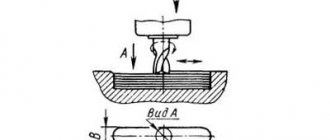
Milling an Archimedean spiral on a disc cam. Machine 6M12P, Lift h=75mm, angle 45, Outer diameter of cam D=250mm, Material - steel 45ХН
TECHNICAL CHARACTERISTICS OF THE MACHINE model 6M12P Dimensions of the working platform of the table in mm 320 1250 Limits of the angle of rotation of the table in degrees 45 Number of rotation speeds of the horizontal spindle 18 Limits of spindle revolutions per minute 31.5-1600 Limits of feed rates in mm/min: longitudinal 25-1250 transverse 25-1250 vertical 8.3-416.6 Spindle drive electric motor power in kW 7
The main advantages of the 6M12P machine: 1. fastening of the tool in the spindle - a mechanized process 2. the screw pair is equipped with an additional periodic control system 3. a safety clutch is installed that protects against overloads 4. the spindle rotation range and machine feed modes are quite high 5. reliability, quality of operations performed and an appropriate level of safety 6. The working surface is increased compared to analogues. By installing additional equipment on the 6M12P milling machine (vice, universal head, gearboxes, etc.), the quality of processing can be significantly improved. The technological capabilities of machines can be expanded by using a dividing head on them.
Contents: General view of the 6M12P machine, kinematic diagram, adjustment, software
Software: KOMPAS-3D 15
Rules for operation and maintenance of the unit
The 6M12P vertical milling machine is installed on a solid concrete foundation and secured with special studs. The lubricant should be constantly changed according to the schedule specified in the passport. After completing work, clean and lubricate the guides. During operation, turn on the cooling system. The machine cannot process materials that do not correspond to its purpose: wood, plastic, aluminum.
The milling machine passport can be downloaded for free from the link – Passport for the 6M12P cantilever milling machine.
Major breakdowns and repairs
Over time, parts wear out, and even the most reliable equipment begins to act up or fail completely. The most common breakdowns that occur with 6M12P are:
- spindle deceleration;
- its full stop;
- slow start, no kick.
Other faults are less common.
Slow and uneven spindle rotation
Slow or uneven spindle rotation occurs when the electrical circuit is broken. You should inspect the cable, contacts, and check the condition of the electrical circuit with a multimeter.
The second reason is wear of the gearbox gears and poor bearing tension. The cover in the housing should be opened. Inspect the gears, assess the percentage of tooth wear and check the engagement. It is possible that small debris has entered the box and is interfering with normal operation. At the same time, check the lubricant and replace it. When the bearings wear out, the spindle begins to beat. You should check the radial and axial runout and tighten the bearings. Replace if necessary.
Important!
The bearings should be thoroughly washed with kerosene, then filled with fresh grease, the brand of which is indicated in the passport.
Spindle jam
You should start inspecting the machine with the spindle bearings and check their condition. Perhaps one of them has collapsed. Then inspect the engagement with the gearbox, check the engagement of the gears when changing gears.
In the absence of an electrical impulse - a push, the spindle assembly does not receive sufficient reinforcement to start rotating. The electrical system should be checked. The spindle will not rotate if debris gets into the assembly. This could be a piece that has broken off from a part, or that has fallen from the outside when the lid is open. Jamming during machine operation occurs under heavy loads and overheating of the spindle, “burning out” of the lubricant.
Slow start
The reason is electrical. If a malfunction occurs, you should first check the voltage in the network. If it falls, the machine will slow down. Then inspect the cable and wires, check the contacts, the presence of phases and zero. After this, look for irregularities in the electrical circuit.
Important!
Slow operation of the spindle assemblies and table movement is possible in the absence of lubrication or inappropriate grade of lubrication. If you fill it with a more viscous one, or in winter with summer, it will slow down the rotation and movement of the units.
Description of the design of the 6N12 cantilever milling machine
Controls for cantilever milling machines 6N12.
The electric motor 10 of the spindle drive is turned on by pressing the “spindle” button on the launch panel 22 located on the machine’s gearbox. The push-button launch pad 22 is duplicated by the launch pad 15, located on the front side of the slide, i.e., the spindle can also be turned on by the “spindle” button on panel 15. The spindle rotation is turned off by the “stop” button on any of the push-button panels 22 or 15. This arrangement of button panels allows the milling operator to start and stop the machine from any place.
The electric motor 3 of the table drive is switched on from two redundant special electrical devices, the so-called command devices, using the corresponding handles. Handle 9 (or its duplicate handle 11) turns on the longitudinal movement of the table in the directions to the right and left, being placed in the corresponding extreme right and extreme left positions, and turns off the longitudinal movement of the table while in the middle position. Thus, the handle has three fixed positions: “feed right”, “feed left” and “stop”.
Duplicate handles 25 and 16 include the transverse and vertical feed of the table from you - towards you, up - down and stop, being placed in one of five fixed positions: “console feed up”, “console feed down”, “sled feed from you” , “feed the sled towards you” and “stop the transverse or vertical stroke”.
Turning on the feed motor to move the table is possible only after turning on the spindle drive motor. If the mechanical feed handles (longitudinal 9 or 11, transverse and vertical 25 or 16) are not in the zero “stop” position, then when the “spindle” button is turned on (on the button panel 22 or 15), the corresponding feed is simultaneously turned on.
To reduce the time for bringing the table with a fixed part to the cutter and retracting the part after the end of the working stroke, the machine provides a fast table speed in the longitudinal, transverse and vertical directions, activated by the “fast” button of the launch panel 22 or 15. The “fast” button turns on the fast speed table, slide or console, provided that the corresponding mechanical feed handles (longitudinal 9 or 11, transverse and vertical 25 or 16) are turned on in the desired direction; if these handles are in the zero “stop” position, high speed will not be activated.
The “Fast” button works only when you press it; when the button is released, the rapid movement of the table is disabled.
It is possible to enable high table speed even when the spindle motor is not turned on.
Setting the speed and feed rate of the table in the 6N12 machine. Rice. 110
Setting the gearbox to a given number of spindle revolutions is done by turning dial 20 with the number of revolutions marked and setting the required number against the pointer arrow 21. Before turning dial 20, you must pull handle 19 towards you. After setting the dial to the required number of revolutions, handle 19 is returned to initial position. In Fig. 110, and shows the gearbox setting at 95 rpm of the spindle.
The spindle rotation direction is reversed using reversing switch 2 (Fig. 109), located in the right electrical cabinet.
The feed box is adjusted to a given table movement using the mushroom 5 and the dial 4 with the feed values printed on it. Switching feeds is done in the same way as switching speeds. In this case, it is necessary to pull the fungus 5 towards you and turn it and the associated dial 4 until the specified feed coincides with the pointer arrow attached to the feed box body. In Fig. 110 shows the setting for a feed of 190 mm/min.
To automatically turn off the feed, the machine has adjustable cams 13, 23 and 24 (Fig. 109); manual movements of the table in the longitudinal, transverse and vertical directions are carried out from the corresponding handwheels and handles.
Coolant is supplied to the cutter from an electric pump (not shown in Fig. 109) through a pipeline and a tip with valve 14 to regulate the amount of liquid supplied. The pump is turned on by switch 1, located in the right electrical cabinet.
Speed switching mechanism of the 6N12 cantilever milling machine
The gear shift mechanism in the 6N12 milling machine. Rice. 84
Speed shift mechanism. To change the speed, you need to turn handle 28 (Fig. 84, a) towards you in the direction of arrow a. In this case, sector 25 will move rack 7, and with it fork 24, hollow shaft 23 and switching discs 21 and 22 to the right. In this case, the switching disks will come out of contact with the rods 20 placed in the holes of the rails 11 and 18.
After this, you need to turn dial 1 until the required number of spindle rotation speeds, from those marked on the conical part of the dial, coincides with the arrow b, fixedly fixed on the housing 4 of the mechanism. The dial 1 is connected to a ring 2, which is fixed to the end of the roller 6. The latter is rigidly connected to a bevel gear 8, which is meshed with a bevel wheel 10, connected by means of a guide key to the shaft 23. Consequently, when the dial 1 rotates, the switching disks also rotate , which will take a certain position relative to the rods 20 of the slats 11 and 18 in accordance with the selected speed. Ball 5, under the action of spring 3, will fix the set position of the switching disks.
Switching disks 21 and 22 have holes located around the circumference in a certain order. Each spindle rotation speed corresponds to its own location of the hole on the disks. When turning the disks 21 and 22, the required speed is selected, while against the rods 20 of the slats 18 and 11, the combination of holes required for a given speed is located on the disk.
Turning the handle 28 in the direction of arrow b will cause the switching disks to move in the direction of arrow d, the disk 21 will rest against the rod 20 of one of the racks 18 or 11, move the racks, while turning the gear 17 meshing with it. Simultaneously with the gear 17, the one sitting on it will turn axis gear 16, due to which the rack with the shift fork 15 will move. The fork 15 fits into the annular groove of the gear block 14 and, as it moves, moves the block along the shaft 13, switching speed.
If block 14, as shown in the diagram, is in the extreme left position, rack 11 will move forward, and rack 18 will be in the rear extreme position.
To switch the block to the extreme right position, a through hole must be located on the switching disks against rack 18, but there will be no hole against rack 11. Then, when moving the disks in the direction of arrow d, the end of the disk 21 will rest against the cylindrical rod of the rack 11 and move the block 14 to the rearmost position. In this case, the rod 20 of the rack 18 will enter the holes opposite it in the disks 21 and 22.
To switch the gear block to the middle position, there must be holes in disk 21 against both racks, but disk 22 will not have holes against the rods of the racks. Then, when moving the disks, the rod of the rack 11 will first enter the hole in the disk 21, and only when it rests against the wall of the disk 22 will the latter begin to switch the block. The path of movement of the block will be less than in the first case, and will end when the block takes the middle position.
If it is necessary to keep the position of the gear block unchanged, through holes should be located against rack 11 in disks 21 and 22, but there will be no holes against rack 18. Then, when moving the disks, the rack rod 11 will enter the holes and switching will not occur.
The mechanism has three pairs of racks, i.e. as many as there are moving blocks in the gearbox.
To facilitate switching speeds and soften shocks, especially if the end of the tooth of one gear gets behind the end of the tooth of another, the rods 20 of the racks transmit force to the racks through the springs 19. For the same purpose, together with the sector 25, a cam K is made, which, when switching gear blocks, acting through the fungus 26, finger 27 and pusher 29 on the push button 30, it imparts short-term rotation to the electric motor and, accordingly, to the elements of the cutting movement drive.
Safety coupling . To protect the feed drive elements from damage, the machine model 6N12PB is equipped with a ball safety clutch (Fig. 84, b). The drive gear 3 is freely mounted on the sleeve 6 and connected to it by balls 5.
By springs 4, balls 5 are pressed against the holes in the flange of bushing 6. The pressing force of the balls is adjusted by nut 1 through pushers 2 so that when the permissible torque is exceeded, the balls are pressed out and rotation from gear 3 to bushing 6 is not transmitted. The sleeve 6, during working feed, is connected to the shaft 9 by a jaw coupling 7 through an intermediate sleeve 8.
Gap elimination mechanism. As is known, to implement the down milling method, it is necessary that there is no excessive clearance in the screw-nut pair of the table feed drive. In the machine model 6N12PB, excess clearance is periodically eliminated using a special mechanism consisting of an additional nut-gear 1 and worm 3 (Fig. 84, c).
To eliminate the gap between the lead screw 2 and the mother screw, remove the cover 7, loosen the screws 6 and turn the worm shaft 3 until the gear nut 1 meshing with it eliminates the gap in the drive.
After adjusting the gap with screws 6, a locking ring 4 is secured through the washer 5, which is connected to the worm X by a pin 8.
Section of the gearbox of a 6N12 cantilever milling machine
Reviews
The 6M12P vertical cantilever milling machine is reliable and durable. It has retained its functionality and is used in the production of single parts and in home workshops. The owners speak positively about the unit.
Members. I bought a vertical milling machine 6b12P from the Gorky plant. It is a copy of the legendary 6P12, but has increased accuracy. Turned it on, checked, everything works fine. There is practically no wear on the guides, the total is 0.1 mm. I scraped off the guides and removed the hole. The machine is after maintenance and used for leveling car heads. I'm happy with the purchase.
The 6M12P model has proven itself well in the manufacture of complex metal parts. It is characterized by high accuracy and ease of control. The multifunctional machine performs complex technological operations with high precision. Sturdy stand and base dampen vibration.
Technical characteristics of the cantilever milling machine 6N12
| Parameter name | 6N12 | 6M12 | 6Р12 | 6T12 |
| Basic machine parameters | ||||
| Accuracy class according to GOST 8-71 and GOST 8-82 | N | N | N | N |
| Table surface dimensions, mm | 1250 x 320 | 1250 x 320 | 1250 x 320 | 1250 x 320 |
| Maximum mass of the workpiece, kg | 250 | 250 | 400 | |
| Distance from the end of the spindle to the table, mm | 30..400 | 30..400 | 30..450 | 30..450 |
| Distance from the spindle axis to the vertical guides of the bed (overhang), mm | 350 | 350 | 350 | 380 |
| Desktop | ||||
| Maximum longitudinal travel of the table by hand (along the X axis), mm | 700 | 700 | 800 | 800 |
| Maximum lateral movement of the table by hand (along the Y axis), mm | 240/ 260 | 240/ 260 | 250 | 320 |
| Maximum vertical travel of the table by hand (along the Z axis), mm | 370 | 370 | 420 | 420 |
| Limits of longitudinal table feeds (X), mm/min | 40..2000 | 12..1250 | 12,5..1600 | 12,5..1600 |
| Limits of table cross feeds (Y), mm/min | 27..1330 | 12..1250 | 12,5..1600 | 12,5..1600 |
| Limits of vertical table feeds (Z), mm/min | 13..665 | 8,3..416,6 | 4,1..530 | 4,1..530 |
| Number of feeds longitudinal/transverse/vertical | 18 | 18 | 22 | 22 |
| Speed of fast longitudinal movements of the table (along the X axis), m/min | 4 | 3 | 4 | 4 |
| Speed of fast transverse movements of the table (along the Y axis), m/min | 4 | 3 | 4 | 4 |
| Speed of fast vertical movements of the table (along the Z axis), m/min | 1 | 1 | 1,330 | 1,330 |
| Spindle | ||||
| Spindle speed, rpm | 63..3150 | 31,5..1600 | 40..2000 | 31,5..1600 |
| Number of spindle speeds | 18 | 18 | 18 | 18 |
| Spindle quill movement, mm | 70 | 70 | 70 | 70 |
| Milling spindle taper | №3 | №3 | №3 | №3 |
| Spindle end GOST 24644-81, row 4, version 6 | 50 | |||
| Milling spindle hole, mm | 29 | 29 | 29 | |
| Rotate the spindle head right and left, degrees | ±45 | ±45 | ±45 | ±45 |
| Machine mechanics | ||||
| Feed stops (longitudinal, transverse, vertical) | Eat | Eat | Eat | Eat |
| Blocking manual and mechanical feeds (longitudinal, transverse, vertical) | Eat | Eat | Eat | Eat |
| Blocking separate feed switching | Eat | Eat | Eat | Eat |
| Spindle braking | Eat | Eat | Eat | Eat |
| Overload safety clutch | Eat | Eat | Eat | Eat |
| Automatic intermittent feed | Eat | Eat | Eat | Eat |
| Electrical equipment, drive | ||||
| Number of electric motors on the machine | 3 | 3 | 3 | 4 |
| Main motion drive electric motor, kW | 7 | 7,5 | 7,5 | 7,5 |
| Feed drive electric motor, kW | 1,7 | 2,2 | 2,2 | 3,0 |
| Tool clamping motor, kW | — | — | — | 0,25 |
| Coolant pump electric motor, kW | 0,12 | 0,12 | 0,12 | 0,12 |
| Total power of all electric motors, kW | 9,825 | 9,825 | 1,87 | |
| Dimensions and weight of the machine | ||||
| Machine dimensions (length width height), mm | 1745 x 2260 x 2000 | 2395 x 1745 x 2000 | 2305 x 1950 x 2020 | 2280 x 1965 x 2265 |
| Machine weight, kg | 3000 | 3000 | 3120 | 3250 |
- Vertical cantilever milling machines with a rotating head 6N13P, 6N13PB. Machine passport, 1955
- Vertical cantilever milling machine 6N12. Care and Maintenance Manual, 1952
- Console vertical milling machine with a rotating head 6N13P. Brief description and instruction manual, 1965
- Horizontal milling machine 6N82, 6N82G. Manual, 1959
- Catalog-directory of replaceable parts for cantilever milling machines 6N82, 6N82G, 6N12, Tula, 1973
- Avrutin S.V. Fundamentals of Milling, 1962
- Avrutin S.V. Milling, 1963
- Acherkan N.S. Metal-cutting machines, Volume 1, 1965
- Barbashov F.A. Milling 1973
- Barbashov F.A. Milling work (Vocational education), 1986
- Blumberg V.A. Milling machine handbook, 1984
- Grigoriev S.P. Practice of coordinate boring and milling work, 1980
- Kopylov Work on milling machines, 1971
- Kosovsky V.L. Handbook of a young milling operator, 1992
- Kuvshinsky V.V. Milling, 1977
- Nichkov A.G. Milling machines (Machinist's Library), 1977
- Pikus M.Yu. A mechanic's guide to repairing metal-cutting machines, 1987
- Plotitsyn V.G. Calculations of settings and adjustments of milling machines, 1969
- Plotitsyn V.G. Setting up milling machines, 1975
- Ryabov S.A. Modern milling machines and their equipment, 2006
- Skhirtladze A.G., Novikov V.Yu. Technological equipment for machine-building industries, 1980
- Tepinkichiev V.K. Metal cutting machines, 1973
- Chernov N.N. Metal cutting machines, 1988
- Frenkel S.Sh. Handbook of a young milling operator (3rd ed.) (Vocational education), 1978
Bibliography:
Related Links. Additional Information
- Milling machines: general information, classification, designation
- Comparative characteristics of cantilever milling machines of the 6N, 6M, 6R, 6T
- Feed box for console milling machines of the 6M : 6M12P, 6M13P, 6M82, 6M83, 6M82Sh, 6M83Sh
- Feed box for console-milling machines of the 6P : 6Р12, 6Р13, 6Р82, 6Р83, 6Р82Ш, 6Р83Ш Feed box for console-milling machines of the 6Т : 6T12, 6T13, 6T82, 6T83, 6Т82Ш, 6Т83Ш
Home About the company News Articles Price list Contacts Reference information Interesting video KPO woodworking machines Manufacturers