Welding is one of the most commonly used methods of joining metals and alloys. Even masters sometimes make seam defects, not to mention beginners. When carrying out such work at home, visual inspection is sufficient. In production, various methods are used to control the quality of the weld, and one of the most advanced is radiographic testing.
X-ray method - brief description
When welding metal workpieces, defects may appear. There are different reasons for this:
- the requirements of the technology for performing certain work are not met or are fulfilled with deviations;
- foreign inclusions entering the weld pool, weakening the strength of the joint;
- poor specialist training or lack of experience in performing highly specialized core tasks.
Any of these reasons leads to a decrease in strength and deterioration in the quality of the weld. It is important to identify flaws in advance.
The X-ray method of testing welded joints is one of the most accurate methods of non-destructive testing. It is used everywhere where exact compliance with quality standards is required and allows you to accurately determine the quality of the welded joint. The non-destructive method makes it possible to identify hidden defects in order to avoid emergency situations during the operation of the structure.
The method is characterized by high accuracy. With its help, specialists receive objective and reliable data about the nature of the flaws. The technique is effective and in demand in the production of pipelines, large tanks, and other critical metal structures and equipment.
Safety precautions
It is important to take precautions when radiographic or x-ray inspection of welded joints. The radiation flux easily penetrates tissues and irradiates them in a fraction of a second. At a large dose it has a damaging effect. This must be taken into account when using the monitoring device.
Basic recommendations for inspectors:
- it is necessary to shield the equipment; lead plates are used for this;
- It is advisable to place the emitter as far as possible from people;
- The time spent in the risk zone must be kept track of;
- Air ionization is possible in the emitter area; electrical equipment must be removed.
The radiographic method of monitoring welded joints in minimal doses is not dangerous. Has minimal impact on humans. If safety regulations are followed, the risk of controller exposure to radiation can be minimized.
Radiographic diagnosis of seams is a modern and accurate method for identifying defects. Manufacturers produce compact models of devices with different beam output powers. You can select the necessary diagnostic equipment. For specialized companies, radiation testing has become a stable source of income. Services are in demand.
GOST and other requirements
The procedure for performing radiographic inspection (including welded joints) is regulated by the provisions of GOST 7512-82. The method of identifying hidden flaws using X-rays is effective at thicknesses from 1 mm to 40 cm. It is possible to work with metals up to 50 cm thick, but this will require the use of special, very powerful equipment.
In addition to X-rays, research also uses bremsstrahlung or gamma radiation. In cases where it is necessary to obtain images, radiographic probing technology is used. To perform control, equipment and tools are used that must meet the following criteria:
- marking signs must meet the requirements of GOST 15843-79;
- the parameters of the radiation source must be in accordance with GOST 20426-82;
- The use of radiographic films is allowed only in accordance with the technical specifications;
- fluorescent or metal intensifying screen;
- light-proof cassettes must ensure a tight fit between the screen and the film;
- the use of plate, groove or wire sensitivity standards is allowed;
- The film should be protected from scattered radiation by a lead screen.
When are radiographic techniques not used?
The radiographic inspection method of welds is not used in several cases:
- If the connection has cracks and lack of fusion with an opening value below standard values. In this case, there is also a discrepancy between the opening plane and the direction of transmission.
- For inclusions and discontinuities having a size in the direction of transmission of less than twice the control sensitivity.
- In case of inclusions and discontinuities, when their projection in the photograph absolutely does not correspond to the image of the constructed parts.
- With sudden changes in metal cracks.
The most accurate way to control metal structures and welded joints is flaw detection with x-ray scanning. It helps to determine the nature, types, location of defects.
Properties and capabilities
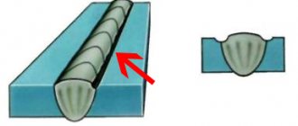
The peculiarity of radiography is that certain types of materials transmit a limited spectrum of waves. In dense structures, the rays are dissected and partially absorbed. In loose textures it’s the other way around. The lower the density of the material, the clearer the image will be.
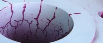
Some chemical elements glow when exposed to X-rays. Thanks to this, special film can be exposed. As a result, specialists receive an x-ray image - an image that shows hidden flaws in the weld. When the structure of the object under study is homogeneous, the image, accordingly, will turn out to be light and in the same colors. Sinkholes, voids and other defects will appear as shaded areas in the image.
The operation of some models of flaw detectors is based on the ability of electricity to pass through ionized air. The effect is directly proportional: the higher the ionization of the air, the better the current flows. Thanks to this principle, the image can be projected not onto film, but onto an oscilloscope.
Large doses of X-ray radiation negatively affect human health. They irradiate cell tissue. Because of this, there is a possibility of developing radiation sickness, which leads to deterioration of health and even death. Therefore, when performing fluoroscopy, it is necessary to strictly observe the rules of behavior and safety precautions.
Features of X-rays
To better understand the essence of radiography, you need to understand the characteristics of the rays themselves, thanks to which control is possible. The rays have properties that allow them to pass through materials. In our case, metal. The higher the density of the metal, the worse the rays pass through. And, accordingly, the lower the density of the metal, the better they pass. Everything is simple here: the lowest density is present precisely in places with defects.
Therefore, the rays pass through the metal unhindered and this is recorded on a special device. Well, if the seam has no defects and the structure is dense, then the rays will not pass through, but will simply be absorbed by the metal. And the higher the density, the greater the degree of absorption.
As for the pictures, everything is simple here too. There are chemicals that literally “glow” when exposed to x-rays. Such substances coat the photosensitive part of the photographic plate, on which the photograph will then appear. This principle is the basis for creating X-ray images of welds.
Now about some other features. You've probably heard that X-ray radiation in large quantities can have a detrimental effect on human health. This is true. The rays easily affect tissues and cells, irradiating them in a matter of minutes. In large doses it can lead to radiation sickness. So you need to be careful if you are using the radiographic weld inspection method.
Another interesting fact: thanks to radiation, the air we are used to is capable of conducting electric current. This is due to the fact that X-rays ionize the air and split its particles into small components, which in turn have an electrical charge.
Flaw detection: scope
X-ray flaw detection has important advantages over other technologies. For example, it allows you to accurately determine the shape, size and spatial location of identified flaws. Thanks to this, control technology is in demand when creating critical metal structures. These include:
- main pipelines for gas and oil production industries;
- construction of nuclear power plants and infrastructure facilities for them;
- water pipelines and other high-pressure pipe lines;
- shipbuilding;
- aircraft manufacturing;
- production of special machinery and equipment;
- other critical structures made of metals.
Decoding
Interpretation of radiographs is carried out in a shaded room using a negatoscope. It is a device whose purpose is to view radiographic images, including radiographs, through transmission. The negatoscope provides the ability to adjust the brightness of the lighting. If its value is too high, small defects may be missed.
After decoding, a conclusion is drawn up. Before resorting to this method, it is necessary to find out what weld defects are detected using radiographic testing. These include:
- undercuts;
- lack of penetration;
- cracks;
- pores;
- foreign inclusions;
- slags
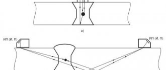
In addition, it is possible to evaluate the amount of concavity and convexity in places where visual inspection is not possible. Abbreviations are used when writing results. So, “T” means a crack, “N” is a lack of penetration, “P” is a pore, “W” is slag, “V” is the inclusion of tungsten, Pdr is an undercut. The size of the defect is indicated next to the letters. The nature of the distribution is also taken into account.
On this basis, shortcomings are divided into groups:
- Separate.
- Chains . There are more than three defects on one line.
- Clusters . Location of at least three defects in one place.
The size of the defect is indicated in millimeters.
Additional Information
It will not be possible to use fluoroscopy everywhere. The technology has its limitations due to the sensitivity of the equipment. The flaw detector will not be able to detect:
- voids located in the direction of radiation (parallel), the size of which is 50% less than the standard parameters for this device;
- voids located in the direction of radiation (parallel), the size of which is half the sensitivity of the device;
- defects that are combined in the image with sharp corners (edges) of the parts being inspected.
Defects that are not included in the list are identified quickly, in full and with high accuracy.
additional information
Before using the radiographic quality control method, you need to know that its diagnostic range is limited by the sensitivity of the device.
Using a flaw detector it is impossible to detect:
- voids that are 50% smaller than the standard values for the specified device and are located in a direction parallel to the action of the x-ray beam;
- inclusions located in the direction of the beam, the size of which is 2 times less than the sensitivity of the device;
- defects that coincide in the photograph with the edges and sharp corners of the elements being tested.
We recommend reading: Types of welding stations and information about them
This method detects all other defects quickly, efficiently and with high accuracy.
Design features of the equipment
Currently, an analysis method that relates to digital flaw detection is in greater demand. The images obtained using irradiation are digitized and displayed on a monitor.
The monitoring detector using gamma or x-rays that pierce the structure under test is a photodiode. It is used in conjunction with a scintillator and is irradiated, as a result of which the photodiode generates light in the visible spectrum. That is, such a scheme transforms radiation into electrical impulses, which are subsequently displayed on the monitor.
To study a large object, detector blocks are moved along it. As a result, specialists receive a continuous flow of information. The data is saved on the computer’s hard drive so that upon completion of the research it is possible to analyze it in detail. In cases where prompt quality assessment is necessary, images are immediately displayed on the monitor.
Radiographic testing
Radiographic testing is a non-destructive testing method that uses X-rays or gamma rays to examine the internal structure of manufactured components, revealing any flaws or defects.
In radiographic testing, the test part is placed between the radiation source and the X-ray film (or detector). Differences in the density and thickness of the material of the part under test will attenuate (i.e. reduce) the penetrating radiation through interaction processes involving scattering and/or absorption. Differences in absorption are then recorded on film(s) or electronically.
In industrial radiography, several imaging modalities are available, techniques for displaying the final image, such as film radiography, real-time radiography, computed tomography, digital radiography and computed tomography radiography.
There are two different radioactive sources available for industrial use; X-ray and Gamma ray. These radiation sources use higher levels of energy, that is, shorter waves, a type of electromagnetic wave. Due to the radioactivity associated with radiographic testing, it is extremely important to ensure strict adherence to local regulations during operation.
Computed tomography is one of the advanced non-destructive testing methods offered to the industry.
CT is an x-ray method that allows you to obtain both transverse and three-dimensional volumetric images of the object under study. These images allow inspection of the internal structure of the test object without the aliasing associated with 2D radiography. This feature allows detailed analysis of the internal structure of a wide range of components.
X-ray inspection devices
The equipment has a constant potential and a high frequency of fluctuations. Gamma rays have a predetermined intensity that deviates by no more than 1%. Therefore, these devices are not recommended for weld quality control. In order to be able to use X-ray equipment for monitoring purposes, it must have the following characteristics:
- radiation stability – from 0.5% and above;
- the fluctuation frequency should not exceed 0.1 Hz.
Control algorithm
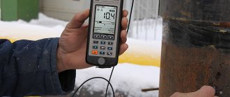
The radiography control technology is simple and fundamentally similar to that used by doctors in X-ray rooms. The person conducting the analysis adjusts the equipment depending on the density of the metal.
We already said earlier that the result depends precisely on how dense the metal is.
The connection cannot be checked immediately after welding. Before inspection, the seam site must be treated. You also need to remove any remaining slag and clean the metal from excess. If the device is mobile, it is placed on the structure.
If the device is fixed in one place, the connection is placed inside.
Operating principle of radiographic inspection equipment
The device, which is used to control welding joints, consists of several units. The main one is the emitter. It generates a stream of particles, which subsequently create an image of hidden defects. The emitter is made in the form of a vessel from which the air is pumped out. Inside are the anode, cathode and filament. The emitter generates particles and gives them acceleration. These are nothing more than X-rays that pierce metal in their path.
The cathode is a source of electrons, which are accelerated due to the difference in potential between plus and minus. But there are still not enough particles for the normal functioning of the installation. They collide with the anode, which ultimately leads to even more electron generation. As a result, a large number of free particles are formed, thanks to which the radiographic flaw detector can fully operate.
The generated electron beams are directed to the object under study. Where the metal is intact and has no flaws, they are almost completely absorbed. And in places that have voids, some of the rays pass through the object unhindered. It is these rays that form the image on the film. As the number of rays increases, the contrast of the image increases. That is, the larger the void inside the metal, the more clearly such a place will be visible in the picture. This is how the size and location of the hidden flaw is determined.
Control method
The radiographic control technique is simple and in many ways similar to conventional radiography, which we do in the clinic. First, the controller or person in charge sets the necessary settings for the device, taking into account the density of the metal. Remember that it is the density that affects the final result.
Next, the welded joint is prepared. It is necessary to remove the slag, process the weld bead and clean the metal. Then either the part is placed in the device (if the control is stationary in a separate room), or the device is placed on the connection (if the control is mobile and compact models are used). The seam must be between the emitter and the film. The emitter turns on, the rays pass through the metal and hit the film. We receive a picture that shows all the defects. Now you can turn off the device and wait 10-20 seconds. The part is then removed from the X-ray machine (or the X-ray machine is removed from the metal). The images are given to a specialist for examination or remain with the controller.
Requirements
For radiographic testing, any commercially produced X-ray devices can be used. Manufacturers do not always indicate in the technical specifications information about fluctuations in the intensity of equipment radiation, since this indicator is not critical in its operation. Since the installation is used to obtain information online, the following requirements are imposed on the equipment:
- The device must generate a sufficiently high flux density. After passing through the object, they must provide the ability to determine the thickness of the part along the entire perimeter of the study.
- Gamma radiation must be of stable intensity.
In order for quality control to be at the proper level, radiometric installations use a stable radiation source. Its power should be sufficient to provide the maximum flux density and the energy spectrum required for research.
Where is radiographic inspection used?
Advantages
- You can check the assembled components
- Minimal surface preparation required
- Detects both surface and subsurface defects
- Provides a permanent audit record
- Check internal defects of complex structures
- Insulate and inspect internal components
- Automatically detect and measure internal flaws
- Measure dimensions and angles inside the sample without cutting
- Sensitive to changes in thickness, corrosion, defects and changes in material density
Areas of use
Radiographic examinations are widely used in;
- Aerospace industry
- Military defense
- Marine industry
- Energy industry
- Petrochemical industry
- Waste management
- Automotive industry
- Manufacturing industry
- Transport industries
Safety regulations
Equipment used to control welding quality emits small amounts of gamma radiation. Nevertheless, safety rules should not be neglected. Basic safety requirements:
- The device must be shielded to prevent X-rays from passing beyond the working area. The room intended for research must be lined with special absorbent screens from the inside. This is necessary to ensure that people who are outside the premises are not exposed to radiation.
- It is advisable to spend as little time as possible near the operating device. If the test is performed in the field, it is better to move away from the equipment at a safe distance. If the test is performed indoors, you should leave it before turning on the unit.
- The operator operating radiographic equipment must wear protective clothing. During operation of the installation, only the operator has the right to be present nearby. Other participants in the process must leave the premises.
- Before you start working with the installation, you must check its serviceability and the correctness of the settings. As practice shows, it is precisely because of incorrect equipment settings or its malfunction that emergency situations most often arise.
- The operator needs to closely monitor his health. It is important that the level of radiation received does not exceed permissible standards. The value can be determined using a dosimeter. It should also be borne in mind that the received radiation doses are cumulative.
- It is especially important in a closed laboratory to monitor the degree of air ionization. The fact is that under the influence of radioactive radiation, the air becomes ionizing. Over time, this can lead to the generation of electricity.
Identification of defects
There are many types of defects that can form during welding work. A special place is occupied by critical flaws that are unacceptable:
- Hot and cold cracks. the former are so called because they are formed before the weld has completely cooled. Cold ones appear after cooling. Both types of flaws can be hidden.
- Pores. One of the most common flaws. Most often, the formation of pores is associated with poor surface preparation. They can also appear as a result of a draft or for other reasons.
- Slag and foreign inclusions inside the weld.
- Burnout. Visually it looks like a through hole. Most often it appears due to low qualifications or inexperience of novice welders. In second place are incorrect settings of the welding machine.
- Undercut The defect appears in the form of a groove, which is located along the length of the weld.
- Influx. When welding, it happens that a melt of the filler material flows onto the base metal without forming a strong connection.
- Lack of penetration. The metal melts, but not enough. The defect occurs due to the fact that the welder has selected the wrong machine settings. Metal that is poorly melted due to low current cannot form a strong weld.
- Loose areas. The weld seam has areas with a weak structure that is easily destroyed.
Defects are determined by a group of specialists based on images taken by the equipment. Requirements for expert photographs and methods for interpreting them:
- Only well-processed and dried images can be decrypted. They must be free from scratches, stains, fingerprints or other imperfections.
- It is recommended to transcribe materials in a darkened room using a special device - a negatoscope.
- The results are recorded in a journal. The expert opinion is transferred to the technical control department.
Advantages and disadvantages of the radiographic method
The control method based on the use of X-rays is characterized by high efficiency. It has a large list of advantages:
- There is no need to spend a lot of time on the initial analysis of the quality of the welded joint. A few seconds are enough to find out whether the connection has flaws or is executed flawlessly.
- Compared to other methods of non-destructive testing, RK is distinguished by its high accuracy of results.
- The method detects a wide range of welding defects.
- RK control technology allows the operator not only to identify a defect, but also to determine its location, size and type.
- Radiography can be used in the field, which expands the scope of its application. For example, in the construction of pipelines, large structures and other facilities.
The other side of the coin is expressed by the following disadvantages:
- X-ray testing involves the use of special equipment, the cost of which is high.
- Disposable consumables - plates or film. Additionally, chemical reagents, screens and other equipment are required.
- Equipment operators must undergo special training and pass exams.
- To obtain an objective result, it is necessary to configure the installation correctly.
- The device generates radiation that is hazardous to health.
Radiographic and ultrasonic testing of welded joints
X-ray and ultrasonic weld testing are the two most common non-destructive testing methods. It is used to detect breaks in the internal structure of welds. The obvious advantage of both of these examination methods is their ability to help establish the internal integrity of a weld without destroying the welded component. We will now briefly look at these two non-destructive testing methods. We will also tell you how they are used and what types of welding defects they can find. We will look at their advantages over other control methods, as well as their limitations.
X-ray inspection technology
Before starting research, it is necessary to thoroughly clean the surface of the object. It is important to set up the equipment correctly: the accuracy of the result depends on it. Radiographic testing is performed in the following sequence:
- Equipment is being installed. The emitter is located on one side of the object under study, and on the opposite side is the flaw detector sensor.
- Turning on the device. After the equipment is initialized, a beam of radiation passes through the weld. It is caught by the sensor. The equipment can operate from the network or from an autonomous power source.
- Displaying the image on the monitor. A sensor that captures X-rays transforms them into an electrical impulse and transmits them to a screen or film, depending on the equipment model.
- The digital signal is recorded in a storage device.
- The received information is decrypted. Identified defects are described in a special journal.
For welds
The procedure for checking classic welds consists of several stages:
- cleaning the welded joint: removing slag and contaminants;
- marking and marking of joints. A sensitivity standard and a marking mark are installed on each site;
- determining the optimal scheme for performing work;
- setting control parameters;
- transillumination;
- processing of footage;
- data decryption;
- Documentation of findings.
For pipelines
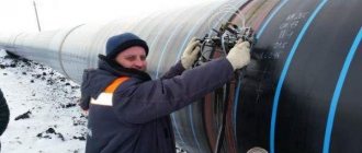
The RK method has been successfully used for a long time in determining the quality of welds of pipes of different diameters. Often research is carried out outside populated areas. Delivering the installation to some places is very problematic, and sometimes even impossible. In such situations, compact mobile devices – crawlers – are used. They are designed in such a way that they can move inside pipelines and be controlled remotely. The minimum diameter of the line is 325 mm.
The object under study can be located anywhere. Not only on earth, but also underground, under water. The equipment is little sensitive to climatic conditions. Thanks to these characteristics, it can be used in different conditions and climatic zones. At the operator’s command, the device moves, stops, focuses and takes pictures of the object.
For tanks
Acceptance of a metal tank begins with a visual inspection of welded joints. Only after this do X-ray analysis begin. In places where welded joints intersect, the films must be placed in the T- and X-shaped directions. According to the rules, the length of images cannot be less than 24 centimeters.
Checking of butt seams is carried out at the places where they meet, on the walls and bottom of the tanks. If an unacceptable defect is detected, an additional photograph is taken. To control the quality of seams on tanks, flaw detectors of at least the fourth category are used. Specialists of at least qualification level 2 are involved in deciphering the results.
For different connection types
RK inspection of seams of various types of joints is carried out in accordance with the provisions of GOST 7512. Before starting work, the characteristics of the metal and the welded joint are determined. To check fillet welds, they are guided by the provisions of GOST 26-2079. This control method is suitable for determining the quality of butt, corner and T-joints, as well as the intersection of welds.
By type of metal
X-ray radiation allows you to check welded joints of different metals. With their help, you can control the quality of the source material. Moreover, in each individual case, the equipment settings need to be changed depending on what metal will be welded, since the patency of the beams is not the same.
The quality of control directly depends on the correct settings. Modern installations not only accurately determine the characteristics of defects: size, shape, location, and others. They can automatically decipher the results obtained.
X-ray weld inspection technology
Each study has a number of unchanged procedures. During X-ray inspection of welded joints, the specialist carries out:
- The object of inspection is being prepared: it is cleaned of rust and other contaminants.
- Next, the object to be examined is positioned so that the weld is located between the receiver of the device and the emitter.
- The specialist turns on the device, and the radiation penetrates the seam and then goes to the receiver.
- Information from the receiver sensor is displayed on the screen and this data is suitable for processing by a specialist and providing to the customer in the form of a report on the examination results.
The procedure can be dangerous to human health, and therefore requires full compliance with safety precautions and special protection.
Application of filmless devices
Digital installations are gradually replacing film cameras from the market. Experts prefer more modern equipment that allows you to display images directly on the monitor and at the same time save data on the drive. There are two types of filmless RK methods:
- Digital. One of the installation modules converts X-ray radiation into electrical pulses, the magnitude of which is directly proportional to the intensity of the radiation. Initially, the flow particles fall on the scintillator, where they are converted into photons. Next, the light elements fall on the photoelectric matrix. Here they generate a small electrical charge, which is read by the device and transferred to the monitor.
- Computer. The method is based on the mechanism of photographically stimulated luminescence. It consists in the fact that part of the crystals of the metal lattice accumulates energy, which, after thermal or optical stimulation, is released and generates light. Barium fluorobromide is most often used as a phosphor. The more energy the memory plate receives, the brighter that part of the image will be. It must be erased from the monitor each time before a new cycle. A powerful beam of light is used for this.
The main advantages of filmless radiography:
- there is no need to treat films with chemical reagents;
- exposure takes less time;
- metal parts of different radiation thicknesses can be analyzed.
Radiographic testing: history of creation
Radiography began in 1895 with the discovery of X-rays (later called X-rays after the man who first described their properties in detail). Soon after the discovery of X-rays, radioactivity . By using radioactive sources such as radium, much higher photon energies can be obtained than from conventional X-ray generators . X-rays and gamma rays were used in the early days of discovery, even before the dangers of ionizing radiation were discovered. Subsequently, new isotopes were discovered, but after the Second World War, such as cesium-137 , iridium-192 and cobalt-60, they became available for industrial radiographic inspection, and the use of the previously used radium and radon began to decline.