Resistance welding (hereinafter referred to as KS) is one of the most common welding technologies used to form permanent joints of metal parts. According to statistics, at least 30% of the total number of welded joints are made using various welding methods. As a rule, KS is used in large-scale production, since the welding process is easily automated and adapted for the creation of robotic conveyor lines. The scope of application of CS is unusually wide - from the manufacture of large-sized products in the aviation industry and automotive industry to miniature microcircuits and semiconductor devices.
Technology
What it is? In accordance with GOST 19521-74 “Welding of metals. Classification "resistance welding is a type of welding of the thermomechanical class, to which the standard includes all types of welding carried out by the combined action of:
- thermal energy used to heat the welding zone in order to ensure the necessary plasticity of the materials of the workpieces being joined;
- applied pressure, which, when squeezing heated areas, combines the connected parts into a monolithic structure.
Thermo-mechanical welding, also called heat-press welding, is classified by the type of heat source used to locally heat the welding area. The most common type of thermomechanical welding is electric contact welding , for which the energy source is an electric current passing through the contact surface of the parts being joined. Compared to electric arc welding, which also uses electric heating, electric contact welding has the following distinctive features:
- Electric arc welding refers to fusion welding. When an electric current passes, the edges of the workpieces being welded are heated to a molten state, after which the liquid metal spontaneously flows into the weld pool. In this case, the parts being welded are not compressed.
- Electric resistance welding, usually simply called resistance welding, is pressure welding. To implement it, when forming a weld, a mandatory approach is required by squeezing the elements to be welded. The clamping is provided either by the electrodes themselves, which supply electric current, or by special devices.
Resistance spot welding - what is it and where is it used?
Resistance spot welding is a type of thermomechanical welding. The process of working on it includes the following stages:
- Combine the parts in the required position.
- They are pressed between the electrodes of the device, the latter acting as a clamping mechanism.
- At the junction point of the clamps, a discharge is applied, heating occurs, deforming under the influence of current, and they are firmly connected to each other.
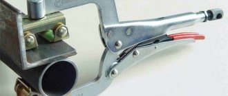
Craftsmen are also attracted by the fact that devices of this kind can be assembled literally from rubbish, and the welding process is as neat and automated as possible. Very often such devices can be found at service stations. Do-it-yourself spot welding for welding a car allows you to level out dents without the need to dismantle body elements, as well as repair hard-to-reach structures.
DIY spot welding for welding a car:
Some industrial designs are capable of performing up to 600 operations per minute. The tool is used for riveting metal structures up to 4 mm. This type of soldering is used for welding reinforcement, flat and corner meshes, as well as frames. In this way it is convenient to connect intersecting rods or rods with flat elements: sheet, strip, channel and other structures.
Spot welding can solve a number of complex problems:
- Provides precise and gentle connections of products without overheating the excess surface.
- Capable of connecting metals of different configurations: ferrous and non-ferrous.
- Perfectly fastens profiles on bends, as well as intersecting metal workpieces, especially in hard-to-reach places.
- The welded areas are highly durable and resistant to further deformation.
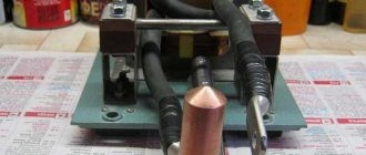
For those who doubt whether it is possible to make the device at home, this is a photo of a spot welding device from a microwave transformer.
Physical and mechanical aspects
The essence of the welding joint lies in the consistent implementation of physical and mechanical processes that contribute to the formation of a permanent welded joint. For this purpose, the CS process flow diagram is divided into the following stages:
- Mechanical pressing of the welded parts between the electrodes - to ensure tight contact between the mating surfaces.
The mating surfaces, due to their roughness, are not ideally smooth, so physical contact of two workpieces is carried out over numerous microscopic areas (so-called microcontacts).
- Passing an electric current through the contact boundary of the mating elements - to heat until the surfaces being connected are melted. At this stage of the welding process, interatomic interaction between the materials of the parts begins, facilitating the formation of a welded joint.
In accordance with the Joule-Lenz law, when an electric current passes through the surfaces of mating parts, heat is released, the amount of which increases with an increase in the strength of the welding current Iw and the ohmic resistance R of the current passage section.
A feature of the contact zone of mating metals is its high electrical resistance Rк, which significantly exceeds the resistance of other sections of the welding circuit - the resistance R of the parts being welded and the resistance of the pressing electrodes Relec.
When current passes through microcontacts, hundreds of thousands of micromeltings occur, contributing to the melting of the entire contacting surface. At the same time, during the welding process, the workpieces themselves are practically not heated, since their resistance is low.
To quickly heat the contact zone, powerful currents are required, the strength of which reaches several thousand amperes. Taking into account the large value of resistance Rk, micromelting occurs within tenths or even hundredths of a second, which determines the high speed of the combustion chamber.
In Fig. Below are CS diagrams illustrating the features of the mating surfaces of two parts being welded:
- (a) – CS diagram;
- (b) – diagram of direct (physical) contact of parts during the welding process.
- Upsetting of the welded parts, which is a compression with increasing force, to create local plastic deformation and the formation of spatial interatomic bonds.
With local heating of mating parts, the plasticity of the metal in the contact zone increases . Under the action of a compressive force, microroughnesses at the boundaries of microcontacts are crushed, after which mutual diffuse penetration of atoms begins to distances commensurate with the parameters of the crystal lattices. New structural bonds are formed, and a welded joint is formed in the contact zone.
- Turning off the electric current supply, cooling the molten metal in the contact zone until its final crystallization. During the crystallization process, the compressive effect of the electrodes is maintained in order to prevent shrinkage defects - looseness, pores and cracks.
Essence of the process
The resistance welding process is based on short-term exposure to current of varying strength. As it passes through the metal, it heats up, thereby significantly increasing the degree of ductility. The main positive features include the following:
- When using the technology under consideration, heat is generated in the body of the workpiece itself. In order to eliminate the possibility of heat spreading throughout the material, its feed rate must be high. That is why special welding equipment is used.
- The supplied current should be high and the heating time should be short. As practice shows, the power during the processing in question amounts to several hundred and even thousands of Amperes. In this case, the exposure time is only a few fractions of seconds. A similar result can only be achieved with internal heat generation in the material.
- The equipment used can significantly increase productivity. Many people call this point an advantage of contact welding. Today, robotic technology is being created that welds large amounts of metal by applying current.
- The processing takes place without the use of filler metal. That is why the technology is considered more economical in terms of the amount of energy consumed.
- Heating occurs directly in the affected area. This is why there are no heat losses when compared with manual arc welding or other technologies.
- The equipment used greatly facilitates the process. In this case, you can use equipment that automates processing. At the moment of exposure to current, a bright flash does not form, therefore, the cost of equipment in the treatment area is reduced.
Spot welding in production
Today, resistance welding is used in the case of conveyor production. Robots can join metal virtually continuously.
We should not forget about some of the disadvantages of resistance welding. It also defines the features of the technology in question. The disadvantages are as follows:
- In order to ensure high quality joints, equipment must be used that can apply pressure to the workpiece.
- The connection can only be carried out if the workpieces can be placed in a special machine. In other words, there are certain restrictions on the size of products.
- If the seam must be large, then the mechanical power and the strength of the supplied current increase significantly. In addition, there are certain restrictions regarding the thickness of the elements being connected.
- The technology is not characterized by versatility and maneuverability. In other words, it is quite difficult to carry out work at the site where the products are placed; for this purpose, home-made structures are often created.
- The resulting seam is characterized by low tightness.
Spot resistance welding
In addition, purchased equipment is characterized by high cost. Serious problems may arise during maintenance. If desired, you can create a homemade design that is highly efficient.
Spot
Spot resistance welding is the joining of parts by contact in separate limited contact areas called weld spots . Spot welding is used in work with thin sheets of metals, most often steel and its alloys, as well as rolled sheets of titanium and aluminum, welding plates of magnesium and copper alloys used in aircraft and shipbuilding, instrument making, the automotive industry, and the production of household products and so on.
For the spot connection method, GOST 15878-79 “Resistance welding...” allows small thicknesses of the workpieces to be joined - from 0.3 to 6.0 mm. However, when using special equipment, a steel rod structure can be installed from reinforcement with rods with a diameter of 16 to 22 mm.
The spot method is the most common KS method, accounting for about 80% of all joints made by resistance welding.
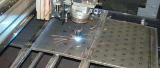
In Fig. Below is a schematic diagram of spot welding and shows a welding machine for performing spot welding operations.
With spot welding, the parts to be welded (item 2 in Fig. 4) are overlapped. The parts are placed between two copper electrodes, one of which serves as a pressing electrode (item 1), the other as a reference electrode (item 3). After pressing the electrodes with force P, an electric current from a transformer (item 4) or other source of electricity is passed through them. The resulting weld point is similar in nature to a mechanical rivet and is not inferior to it in connection reliability .
Depending on the arrangement of the electrodes, the following types of point CS are distinguished (see figure below):
- pos. (a) - double-sided spot welding, in which both parts (1 and 2 in diagram a) are pressed between vertical electrodes;
- pos. (b) – one-sided spot welding, characterized by fixing both electrodes on the upper part 3, laid on top of part 4. The copper lining 5 is provided to increase the current intensity that heats the contact zone.
Schemes of unilateral and bilateral point CS.
Operating principle of contact welding machines
The essence of the contact welding method is that the surfaces being bonded are simultaneously heated to a plastic state and subjected to mechanical deformation. Therefore, there are two main blocks in the welding machine:
1. Mechanical, including:
- the electrodes themselves (in spot welding machines they are made in the form of clamping pliers, in seam welding machines - in the form of rollers);
- compression drive;
- rotation drive (for roller electrodes);
- clamping and upset drive (for butt welding).
2. Electric. This block consists of:
- welding power transformer;
- output voltage regulator, which switches the number of turns in the primary winding of the transformer;
- a secondary circuit through which current is supplied to the parts;
- primary circuit breaker to turn the current on and off;
- cycle regulator - a device that sets the sequence of welding operations, their duration, and regulates other necessary parameters.
Auxiliary blocks:
- Pneumohydraulic - contains filters, devices for lubricating moving parts, a system supplying air to the compression drive (fittings, air valves, valves) and a pressure regulation system;
- Water cooling unit of the device.
The principle of operation is that the resistance welding area is compressed or rolled between two copper electrodes, to which a low voltage and high current current is supplied. In some devices, the current can reach tens of thousands of amperes. The voltage in the secondary winding is low, less than 15 V. The compression force between the electrodes varies from a hundredth of a newton to 100 kilonewtons.
The main advantages of this method are:
- speed - processing one point or butt connection takes a fraction of a second;
- economical - no oxygen, shielding gas or additive is required, almost no water and air are consumed, electrodes wear out slowly;
- simplicity - the ability to obtain a strong and reliable seam with a small number of controlled parameters, which even inexperienced welders can do;
- safety – the air is not polluted with harmful smoke, the risk of fire is minimized;
- the ability to easily automate the process and put it on stream.
The disadvantages of this method include:
- expensive equipment;
- the need to use high current (over 1000 A);
- complex technology of multi-point welding or welding several seams at the same time.
In addition, this method is not always suitable for joining surfaces of different metals or alloys, or for metals with low contact resistance (such as copper).
Embossed
Relief welding is a type of resistance welding in which the initial contact of the joined surfaces is carried out along pre-formed protrusions - reliefs . Reliefs are formed in advance by stamping, rolling or another method. The presence of raised protrusions on both parts is allowed.
In Fig. Below are diagrams of the relief CS:
- diagram (a) – for connecting flat parts;
- diagram (b) – for welding flat and three-dimensional parts.
The diagrams indicate the following positions:
- pos. 1 – upper electrode;
- pos. 2 – flat part with stamped relief;
- pos. 3 – smooth part without reliefs;
- pos. 4 – bottom electrode;
- pos. 5 – three-dimensional detail with relief.
When current passes through the contact points of the relief surface of the parts, pos. 2 (diagram a) or pos. 5 (diagram b) with a smooth part (item 3), the reliefs begin to melt. When exposed to pressure, the reliefs are deformed, creating tight contact over the entire nominal surface of the flattened part.
At its core, relief welding is an analogue of spot welding, the main difference between them is the following -
the contact of parts in relief welding depends on the shape of the surface, while in spot welding the degree of contact is determined by the shape of the working part of the electrodes .
Embossed KS is used in automobile production for fixing volumetric parts (fasteners, brackets, brackets) on flat sheet products (hood cover, doors, etc.). In instrument making, embossed KS is used for welding wire to parts of small thickness.
Types of spot welding.
Spot welding happens:
- Single point.
- Two-point.
- Multipoint.
Applicable for processing reinforcement, meshes, frames; for fastening electronic parts up to 0.02 mm in size; for welding steel products, sheets up to 20 mm thick; in the production of production equipment.
Suture
Seam welding is a method of forming a weld from a series of weld points that sequentially overlap each other . In Fig. Below is a diagram of seam welding, according to which the parts being welded are pressed (item 1), their movement and current is supplied to the place of contact of the parts is carried out by rotating roller electrodes (item 2).
By analogy with spot welding, parts are assembled overlapping each other and heated by short-term pulses of electric current. The result of each pulse is a weld point. To obtain a tight or hermetically sealed seam, select the appropriate pause mode between current pulses and the required rotation speed of the roller electrodes.
Seam welding, also called roller welding, is recommended for the manufacture of sealed containers such as barrels or tanks. The optimal thickness of sheets for seam welding is 0.2-3.0 mm.
Butt
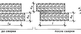
Butt welding is a KS method characterized by the connection of welded products over the entire area of their contact . Using the butt method, rod-type products, rods, wire, strips, pipes, and rolled products of complex profiles are welded.
In Fig. Below is a diagram of resistance butt welding.
In production practice, two types of butt joints are used:
- Resistance butt welding performed in the following sequence:
- the workpieces are pressed tightly against each other by the surfaces being welded;
- An electric current is passed through the compressed workpieces;
- After heating the mating surfaces until a plastic state occurs, the parts are upset with the simultaneous switching off of the current supply.
Resistance welding is used for small parts (sectional area no more than 200 sq. mm) and a simple cross-section in the shape of a circle or square.
- Flash butt welding, during which the parts to be welded are brought closer together while the welding current source is turned on. In this case, the contact of the surfaces occurs through microcontacts, the total area of which is in fact much less than the nominal calculated area of the joints. Because of this, the current passing through the microcontacts is high enough to almost instantly melt the metal of the microcontacts, creating liquid bridges. Heating of the joints of workpieces is accompanied by the continuous formation and destruction of jumper contacts, as a result of which continuous layers of molten metal appear at the joints. After upsetting with an increased speed of approach, the ends of the parts are closed, and the main part of the liquid metal is squeezed out of the welding zone and, after cooling and crystallization, forms a thickening called a flash.
Flash welding is used for parts with a cross-sectional area of up to 100,000 square meters. mm of various cross-section configurations.
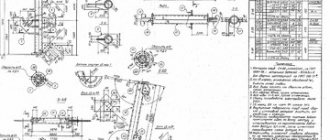
Designation on the drawing
When designating KS on drawings or diagrams, they are guided by two standards:
- GOST 2.312-72, which sets out the ESKD requirements for applying conventional images and designations of welds and single weld points;
- GOST 15878-79, which regulates the main parameters of elements of welded joints of KS.
According to the ESKD, visible single weld points are indicated by the symbol “+”, hidden ones are not marked at all. Visible seams are marked with a main line, hidden seams of the CS are indicated with dashed lines . All information about the parameters of the joint is provided on the leader line (for a seam on the front side) or under it (for a seam on the back side). The necessary information about the seam is taken from GOST 15878-79. The following designations are used in the KS type designation:
- CT - for point CS;
- Kr - for relief KS;
- Ksh - for suture CS.
In Fig. Below is a symbol for a spot welding joint indicating the diameter of the weld spot
Surface preparation
The condition of the mating surfaces of parts (degree of roughness, presence of mechanical impurities and oxide films) subject to welding significantly affects the quality of the welded joint and the service life of the electrodes. In general, the following requirements are imposed on the mating surfaces of parts welded using any of the welding joint methods:
- surfaces should not have bulges, depressions or burrs;
- the planes of the contact zone of the joined workpieces must coincide;
- the electrical resistance of the “part-electrode” contact should be minimal;
- the resistance of the “part-to-part” contact should be almost the same over the entire contact area.
To implement these requirements, the following preparatory activities are carried out:
- cleaning surfaces from contamination;
- degreasing;
- removal of scale and oxide film;
- passaging to slow down the growth of the oxide film.
The choice of technology for preparing surfaces for CS depends on the material of the parts and the nature of production . For KS in small-scale production conditions, machining, straightening, degreasing and etching of surfaces are provided. In high-volume production, surface preparation is usually not performed due to the high quality raw materials used.
Cars
Resistance welding is a fairly universal way of creating permanent connections of metal products. With its help, you can even surfacing metal electrode wire onto parts of critical units using pulsed electrical discharges. The main feature of the classification of equipment for contact welding is the type of connections made, according to which contact units are divided as follows:
- for point CS;
- for seam-butt welding (mainly thin-walled pipes);
- for butt welding;
- for suture and
- relief KS.
Machines for CS must perform the following functions:
- ensuring the required pressing pressure of the workpieces being welded;
- generating a current of sufficient strength necessary to implement this type of CS;
- precise dosing of the time of exposure of the electrode to the workpiece.
To meet these requirements, CS installations are equipped with two interconnected functional systems:
- electrical, “responsible” for the flow of current of the required strength, frequency and amplitude, a given duration of flow;
- mechanical, composed of structural elements that form the conditions for compression, movement, and upset of welded parts.
KS machines are high-tech factory-made equipment. They are accompanied by step-by-step technical instructions with a detailed description of the welding techniques performed, depending on what type of workpiece is to be welded. Currently, many home craftsmen manage to assemble devices with their own hands for performing CS at home.
The logic of the masters is simple - to perform one-time technical tasks, it is easier to create a simple device with your own hands, using a used car battery or a microwave transformer, than to spend money on purchasing expensive professional equipment.
Inverter spotters (from the English spot - point, spot, place), used for one-sided point KS in automotive straightening work, have become widely popular.
What characteristics should you use to choose a device?
When choosing equipment, you need to take into account the following parameters: operating modes of the device, power, material thickness, electricity consumption.
Operating modes of the device
Depending on the properties of the current, the operating mode of the unit can be hard or soft.
In the first case, high-density current is used, the welding cycle is less than 1.5 s. In this mode, productivity increases, but the parts to be joined must be strongly compressed. For work, electrodes are used whose diameter exceeds the total cross-section of the elements being soldered several times.
Welding can be performed in hard or soft mode.
In the second case, a current of lower density is used, the welding cycle is increased to 5 s. This allows you to reduce the pressure of the pliers on the workpieces and work with electrodes whose diameter is equal to the thickness of the parts.
Voltage power
The welding machine can be connected to a single-phase line of 220 V and a three-phase line of 380 V. Power consumption, depending on the model, can range from 3 to 12 kW. It is not recommended to connect equipment operating with a power higher than 5 kW to a standard electrical network, because The wiring may melt.
Thickness of welded sheets
This parameter determines the maximum cross-section of parts that can be welded by the unit. When soldering thicker workpieces, poor-quality seams are obtained.
The parameter designation can be common or separate. For example, in the first case – “5 mm”, in the second – “2.5+2.5 mm”, but the meaning of these parameters is the same.
Industrial models capable of welding 3 steel sheets simultaneously are designated “3+3+3 mm”.
Economical consumption
Cheap units are designed for manual control. Some models only work at maximum current, because... its adjustment is not provided. The welder independently squeezes the pliers and monitors the period of contact of the electrodes until the desired penetration is achieved.
The power of the welding machine is one of the main characteristics.
To ensure a high-quality seam, the transformer is first tested on rough blanks of the same cross-section as the main elements. This is done to determine the pressing time. After this, you can proceed to finishing work.
Models are available in which the current strength is regulated - synergetic (microprocessor) control. This greatly simplifies welding work. The operator indicates on the instrument panel the type of connection and the thickness of the workpieces. The control mechanism independently selects the optimal parameters for operation and turns on/off the current supply. The master’s task is only to bring the electrodes to the junction of the parts. But this is expensive equipment.
We recommend reading: How to make spot welding for a 18650 battery
Defects of CS
CS defects are divided into external and internal.
External defects include the following shortcomings and errors:
- cracks leading to separation of the base metal from the weld point;
- burns and burns, the external signs of which are deep dents, areas of discoloration, through fistulas;
- metal splashes, which represent the ejection of part of the melt from the welding zone;
- breakout points;
- darkening of weld points;
- deep dents from electrodes, irregular dent shape;
- corrugated areas of the surface of welded parts;
- extrusion of metal onto the surface of a point or seam.
Internal defects of the CS include the following:
- lack of penetration, characterized by the absence of a cast core in the area of the weld point or its small size. As a result, the parts in this place are not connected firmly, which will lead to destruction of the product during its use (for a point connection) or to a violation of the tightness in the case of a seam connection;
- internal splashes, pores and shells
In Fig. Below are typical CS defects and the reasons that cause them
Quality control of finished welded joints
The quality of welded assemblies produced by various welding methods is assessed in order to determine their compliance with the technical requirements for manufactured products. Destructive and non-destructive testing methods are used to identify CS defects .
The main methods of non-destructive testing include the following:
- External inspection of the welded contact joint. A feature of this method in relation to CS is the complication of quality control due to the tight pressing of the parts to each other, hiding some of the shortcomings of the connection.
When assessing welding results during an external inspection of a batch of similar products, it is recommended to have a standard sample of the welded assembly.
- Pneumatic tests to check the tightness of seams made by seam welding. The finished product is filled with low-pressure compressed air and immersed in water so that the escaping air bubbles indicate possible locations of leakage.
- X-ray scanning used to control critical products operating under dynamic loads (axles, traction, etc.).
- Ultrasonic testing or ultrasonic testing, which has become widespread due to the industrial production of easy-to-use compact ultrasonic testing devices.
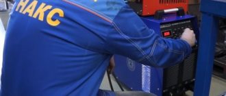
In Fig. Below is shown the working moment of ultrasonic testing using the A1212 Master ultrasonic flaw detector for searching for cracks, lack of fusion and other internal defects.
Destructive testing methods are based on selecting a part of manufactured products (so-called technological samples) and making sections of parts along the seam to determine defects. The main methods of destructive testing include:
- mechanical tests, during which welded joints are tested for strength and ductility;
- metallographic tests, during which the depth of metal penetration is determined, cavities, cracks, lack of fusion and other internal defects are identified.
Results
The use of resistance welding from an inverter with your own hands allows you to connect metals and alloys of different grades using a high temperature electric current, which provokes plastic deformation of the contact zone of parts when they are compressed.
Resistance welding technology has a wide range of applications: it is actively used in everyday life and on an industrial scale in the manufacture of large batches of the same type of metal products.
It is important to follow the technology, put the resistance welding designation on the diagram, use the electrodes recommended by the manufacturer, select the correct operating modes of the unit, then the welds will acquire high quality and durability.
Consumables and additional machine elements
In welding production, the category of consumables includes piece electrodes and welding wire, filler rods and ceramic linings, that is, those materials and products that need to be replenished as they are consumed during use. In the case of CS, only electrodes are consumables, since due to the localization of the weld pool, additives are not required and there is no need for gas protection of the welding zone.
Unlike electric arc welding, in the KS process it is not the electrodes themselves that melt, but the parts being connected.
The functions of the electrodes used in KS machines are more diverse than those of traditional arc welding electrodes. The main “responsibilities” of CS electrodes include the following:
- closing the electrical circuit to supply current to the mating parts;
- melting of parts at the point of contact;
- transmission of mechanical force to compress parts;
- heat removal from the welded joint;
- participation in the movement of welded workpieces during seam welding.
Intense thermal deformation effects on electrodes lead to rapid wear of their working surface, therefore, the materials of electrodes for CS are subject to increased requirements for strength, wear resistance and resistance to chemical aggression from atmospheric air and the material of parts.
Electrodes must effectively remove thermal energy from the resistance welding site. Practice has shown that in order to provide the necessary compressive force and the optimal mode of conducting electric current in the contact zone, the electrodes must have a certain geometric shape of the working surface in contact with the workpieces.
Depending on the chemical composition of products welded using KS technology, the following geometry of the working surface of the electrode is recommended:
- for CS of low-carbon steels – flat surface;
- for welding alloy and high-carbon steels, copper and aluminum - spherical surface.
Using pure copper is not effective, since it is a ductile material and does not restore its geometric shape between welding cycles.
In addition, the cost of pure copper is high enough to be used in consumables that require regular replacement. Copper alloys are most often used, in which chromium, zinc, cadmium, zirconium, beryllium, and magnesium serve as alloying elements .
Electrodes can be straight, shaped, or complex curved. For seam welding, the electrodes are roller-shaped.
Welding process
Regardless of the technology used, welding is carried out in several stages:
- The surfaces to be joined are processed to ensure more precise contact between the parts. The electrical voltage over the entire surface of the parts must be the same. To do this, the surfaces are made as smooth as possible by treating them mechanically, using etching, stripping, straightening or degreasing.
- Then the parts are clamped with a special mechanism or simply pressed manually - in this case, the quality of the seam will be lower due to insufficient pressure. Pressure enhances the diffusion of metal and allows you to create a uniform, strong seam.
- An electric current is applied to the surfaces to be connected; thermal energy melts the desired area of the metal, forming a liquid core in which bonds are formed between the surfaces. The pressure exerted on the metal prevents the liquid core from splashing out beyond the working area.
- After the current is turned off, the liquid core cools, forming a weld seam. In terms of strength, if the technology is followed, it is not inferior to the metal of the parts being connected.
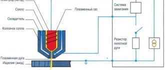
To work with refractory and soft metals, it is better to use a plasma apparatus. This plasma welding machine can work with any metals and surfaces.
Need to carry out welding work at home? Find out from this publication whether you can use a welding machine at home.
When carrying out such work, do not forget about eye protection. You can read more about choosing a chameleon welder mask here.
Different metals require processing using special technology; for example, the surfaces of aluminum parts must be treated no earlier than 10 hours before the joining procedure.
Additional items
The basic configuration of equipment for contact welding is represented by actuators of electrical and mechanical systems, ensuring the operation of welding equipment in normal modes. As additional elements, the welding equipment may contain parts and mechanisms designed to expand the functionality of this unit, as well as to facilitate the work of the welder-operator. The most popular are:
- feed cylinders with adjustable stroke;
- electrode lowering control devices;
- pneumatic pliers;
- hand pliers for spot welding;
- drills for spot welding;
- spotter series accessories;
- straight and shaped consoles for fixing electrodes;
- shoulders for spot welding machines.
Safety precautions during work
When operating point-type units, you must follow the safety rules:
- there should be no damage to the insulation of electrical cables or exposed contacts;
- the unit must be grounded;
- when connecting equipment to the electrical network, the contacts must correspond to the nominal values;
- it is necessary to use automatic machines;
- setup and maintenance of the device during operation is carried out only after disconnecting from the power supply.
We recommend reading Homemade spot welding machine
Carrying out welding work is associated with increased danger for the welder.
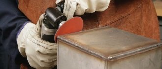
The welder must wear thick overalls, a special mask or goggles, and dielectric gloves. At the same time, the handle of the pliers is reliably isolated. When working indoors, you need to wear a respirator and an exhaust hood.