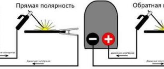
What device regulates the current in a circuit?
Resistors are elements widely used in electrical and radio engineering, automation and electronics, and which were previously called simply “resistances”. (The word “resistor” is derived from the Latin word resisto - I resist). There is a wide variety of shapes and sizes of resistors depending on the purpose and amount of power dissipated. Types of practically used resistors: Resistors are classified into fixed resistors (the resistance of which is not adjustable), variable adjustable resistors (potentiometers, rheostats, trimming resistors) and various special resistors, for example: nonlinear (which, strictly speaking, are not ordinary resistors due to nonlinearity CVC), thermistors (with a large dependence of resistance on temperature), photoresistors (resistance depends on illumination), strain gauges (resistance depends on the deformation of the resistor), magnetoresistors, etc. Rheostats are devices whose resistance can be adjusted. They are used when it is necessary to regulate the current in a circuit. A rheostat differs from a variable resistor in its design and significant power.
Rheostat (potentiometer, variable resistance, variable resistor, from the Greek ρηος - flow and Greek στατος - standing) is an electrical device used to adjust and obtain the required resistance value. As a rule, it consists of a conductive element with a device for regulating electrical resistance. The resistance can be changed either smoothly or stepwise.
By changing the resistance of the circuit in which the rheostat is connected, it is possible to achieve a change in the value of current or voltage. If it is necessary to change the current or voltage within small limits, the rheostat is connected in series to the circuit. To obtain current and voltage values from zero to the maximum value, a potentiometric connection of a rheostat is used, which in this case is an adjustable voltage divider.
The use of a rheostat is possible both as an electrical measuring device and as a device as part of an electrical or electronic circuit.
[edit] Main types of rheostats Wire rheostat. Consists of a wire of high resistivity material stretched over a frame. The wire passes through several contacts. By connecting to the desired contact, you can obtain the desired resistance. Slider rheostat. Consists of a wire of high resistivity material, turn by turn, stretched over a rod of insulating material. The wire is covered with a layer of scale, which is specially obtained during production. When moving the slider with the contact connected to it, the layer of scale is scraped off, and electricity flows from the wire to the slider. The more turns there are from one contact to the other, the greater the resistance. Such rheostats are used in the educational process.
Source
Current and voltage regulator
The main operating elements of regulators are thyristors, as well as various types of capacitors and resistors. In high-voltage devices, magnetic amplifiers are additionally used. Modulators ensure smooth adjustments, and special filters help smooth out interference in the circuit. As a result, the electric current at the output becomes more stable than at the input.
DC and AC regulators have their own characteristics and differ in their main parameters and characteristics. For example, a DC voltage regulator has higher conductivity with minimal heat loss. The basis of the device is a diode-type thyristor, which provides a high pulse supply due to accelerated voltage conversion. Resistors used in the circuit must withstand a resistance value of up to 8 ohms. Due to this, heat losses are reduced, protecting the modulator from rapid overheating.
The DC regulator can function normally at a maximum temperature of 40 C. This factor must be taken into account during operation. Field-effect transistors are located next to thyristors, since they only pass current in one direction. Due to this, the negative resistance will be maintained at a level not exceeding 8 ohms.
The main difference between the AC regulator is the use of exclusively triode-type thyristors in its design. However, field-effect transistors are used the same as in DC regulators. Capacitors installed in the circuit perform only stabilizing functions. High-pass filters are very rare. All problems associated with high temperatures are solved by installing pulse converters located next to the modulators. AC regulators whose power does not exceed 5 V use low-pass filters. Cathode control in such devices is performed by suppressing the input voltage.
During adjustments in the network, smooth current stabilization must be ensured. At high loads, the circuit is supplemented with reverse direction zener diodes. To connect them together, transistors and an inductor are used. Thus, the current regulator on the transistor performs current conversion quickly and losslessly.
Special attention should be paid to current regulators designed for active loads. The circuits of these devices use triode-type thyristors, capable of passing signals in both directions. The anode current in the circuit decreases during the period when the maximum frequency of this device decreases. The frequency may vary within the limits set for each device. The maximum output voltage will depend on this. To ensure this mode, field-type resistors and conventional capacitors capable of withstanding resistance up to 9 Ohms are used.
A rheostat is a control device that can change current and voltage
Electrical circuit components
Electrical networks are focused on transferring electricity from source to consumer, which are the main elements of the chain. But besides them, other components are also inserted into the electrical circuit, for example, control elements, which include a rheostat or any other device with the same principle of operation. A rheostat device is a conductor of a certain cross-section and length, through which the resistance of the conductor can be determined. Of course, its material is also discussed. By changing the resistance of the device, or more precisely, the conductor, you can regulate the amount of current and voltage in the network. So, a rheostat is a device that regulates voltage and current.
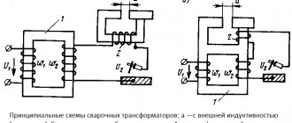
Voltage and current regulator circuit
Before considering the voltage regulator circuit, it is necessary to at least become familiar with the principle of its operation. As an example, we can take the thyristor voltage regulator, which is widely used in many circuits.
The main part of such devices as the welding current regulator is the thyristor, which is considered one of the powerful semiconductor devices. It is best suited for high power energy converters. The control of this device has its own specifics: it opens with a current pulse, and closes when the current drops almost to zero, that is, below the holding current. In this regard, thyristors are mainly used to operate with alternating current.
You can regulate alternating voltage using thyristors in different ways. One of them is based on skipping or prohibiting entire periods or half-cycles from the controller output. In another case, the thyristor turns on not at the beginning of the voltage half-cycle, but with a slight delay. At this time, the output voltage will be zero, and accordingly no power will be transferred to the output. In the second part of the half-cycle, the thyristor will already conduct current and voltage will appear at the output of the regulator.
The delay time is also known as the opening angle of the thyristor. If it is set to zero, all input voltage will go to the output and the voltage drop across the on-SCR will be lost. When the angle begins to increase, the output voltage will decrease under the action of the thyristor regulator. Therefore, if the angle is 90 electrical degrees, the output will be only half the input voltage, but if the angle is 180 degrees, the output voltage will be zero.
The principles of phase regulation make it possible to create not only a current and voltage regulator for the charger, but also stabilization, regulation, and soft start circuits. In the latter case, the voltage increases gradually, from zero to the maximum value.
Based on the physical properties of thyristors, a classic current regulator circuit was created. In the case of using coolers for diodes and a thyristor, the resulting regulator will be able to supply up to 10 A to the load. Thus, at a voltage of 220 volts, it becomes possible to regulate the voltage on a load with a power of 2.2 kW.
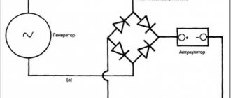
Such devices consist of only two power components - a thyristor and a diode bridge, designed for a current of 10 A and a voltage of 400 V. The diode bridge converts alternating voltage into a unipolar pulsating voltage. Phase adjustment of half-cycles is performed using a thyristor.
For a parametric voltage-limiting stabilizer, two resistors and a zener diode are used. This voltage is supplied to the control system and is 15 volts. The resistors are connected in series, thereby increasing the breakdown voltage and power dissipation. Based on the simplest parts, you can easily make homemade current regulators, the circuit of which will be quite simple. As a specific example, it is worth taking a closer look at the thyristor welding current regulator.
Design and principle of operation
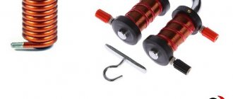
If we consider the rheostat design, then it is necessary to note several of its main parts:
- This is a ceramic tube;
- a metal wire is wound around it, the ends of which are brought out to contacts located at opposite ends of the ceramic tube;
- a metal rod is installed above the tube, on one side of which a contact is made;
- A moving contact is attached to the rod, which electricians call a slider.
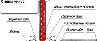
Now how does it all work. Pay attention to the picture below.
The first position (a) is the contact (moving) in the middle. This means that the current will only pass through half of the device. The second position (b) indicates that the conductor is fully engaged. That is, its length is maximum, which means the resistance is maximum, while the current strength has decreased. It is clear that the greater the resistance, the less the current. The third position (c) – here everything is the other way around: the resistance decreases, the current increases.
How is a rheostat connected to a circuit?
Firstly, this device is connected to the electrical circuit only in series. Secondly, one of the contacts is connected to a slider, with the help of which the amount of current in the circuit is regulated. But it should be noted that this control element can also be used to regulate the voltage in an electrical circuit. Several circuits with one or two resistances can be used here. It is clear that the fewer elements in an electrical chain, the simpler it is.
Rheostats are universal devices. Today they are used not only to control current and voltage. For example, on televisions they are installed to increase or decrease the sound. Yes, and switching channels is indirectly related to them.
And one moment. In electrical diagrams the designation of these devices is as follows:
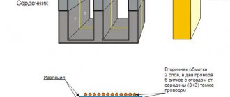
The first figure shows the connection diagram in more detail, where the red rectangle is the conductor wound onto a ceramic base. The blue line is the contact through which the power wire is supplied. The green arrow is the slider. It is directed to the left, which means that by moving the slider to the left, we reduce the resistance of the conductor. And, conversely, we move the contact to the right, increasing the resistance.
The second drawing is more simplified. It just has a rectangle showing the presence of resistance, and an arrow that shows that this indicator can be changed.
Of course, all this information concerns the simplest elements. But it should be noted that rheostats can be different, it all depends on the place where they should be installed. There are also differences in the underlying conductive material. For example, this could be coal, metals, liquids and ceramics. In addition, the cooling process is carried out by air or using liquids, and this can be not only water.
Source
Regulator characteristics
Self-made regulators can be manufactured and installed as a temporary or permanent device. The main characteristics that the regulator must have are:
- Possibility of gradual adjustment. It is best if the regulator has a special wheel with which you can smoothly adjust the difference between the reception and output of the signal.
- Power at which the regulator can operate stably. The higher the current strength at which it will operate without negative consequences for itself, the better for the device itself.
- An indicator of the maximum power that the regulator can withstand over a short period of time.
- Input voltage range.
- The type of signal that can be adjusted (direct or alternating current).
- Regulator control. It can be mechanical (using various mechanisms) or electronic (installed using remote controls or programming).
Guess the riddle:
On one island there is an apple tree with a boy, and on the other there is a hospital with a grandmother. Bridge between the islands. The boy needs to bring 2 apples to his grandmother, but the bridge can only support one boy and one apple. After the boy passes, the bridge will collapse. And there are sharks in the water. How can he move the apples? Show answer>>
A cat is sitting on the window. The tail is like a cat, whiskers, paws, ears are like a cat, but she is not a cat herself. Who is this? Show answer>>
There is a pond on the window, and fish live in it. There are no fishermen on the glass shores. Show answer>>
Rheostats. Types and device. Operation and features
In many electronic devices, you need to change the current to control the volume of the sound. Let's consider a device (rheostats) with which you can change the current and voltage. The current strength depends on the voltage at the ends of the circuit section and on the resistance of the conductor: I=U/R . If you change the resistance of the conductor R , then the current strength will change.
Resistance depends on the length L , on the cross-sectional area S and on the material of the conductor - resistivity. In order to change the resistance of a conductor, you need to change the length, thickness or material. It is very convenient to change the length of the conductor.
For example, a circuit consisting of a current source, a switch, an ammeter and a conductor in the form of an AC resistor made of wire with high resistivity.
By moving contact C along this wire, you can change the length of the conductor that is involved in the circuit, thereby changing the resistance, and therefore the current strength. Therefore, it is possible to create a device with variable resistance, with which you can change the current strength. Such devices are called rheostats.
A rheostat is a device with variable resistance that serves to regulate current and voltage.
Description of voltage regulators
This device is designed to regulate the level of the outgoing signal that is transmitted to any device. The simplest such device is a rheostat. This device has a slider that allows you to mechanically adjust the power supplied. A significant disadvantage of such a device is the possibility of its use only in circuits with low power. If the voltage is high enough, the rheostat will quickly overheat and fail.
To understand what elements will be needed to make a regulator, you need to understand what types of these devices there may be. All of them are divided according to the type of output signal:
- unstabilized and stabilized;
- analog and digital.
The first types can be used without the use of printed circuit boards and microcircuits. Therefore, when choosing elements for making a regulator yourself, it is better to opt for resistors, transistors or thyristors. But the use of analog or digital printed circuits without special knowledge in radio electronics is unlikely to work.
Rheostat device
A metal conductor, which is made of a material with high resistivity, is wound around a cylinder made of ceramic. This was done so that with a small change in length the resistance would change significantly. This metal wire is called winding. It is so called because it is wound on a ceramic cylinder.
The ends of the winding are brought out to clamps, which are called terminals. At the top of the rheostat there is a metal rod, which also ends with terminals. A sliding contact called a slider can move along the metal rod and along the winding. Since the sliding contact has this name, such a rheostat is called a slider rheostat.
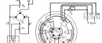
Operating principle
The slider rheostat is connected to the circuit through two terminals: the lower one from the winding and the upper terminal, where the metal rod is. When it is connected to a circuit, the current through the lower terminal passes along the turns of the winding, and not across the turns. Next, the current passes through the sliding contact, then along the metal rod, and again into the circuit.
Thus, only part of the rheostat winding is used in the circuit. When the slider moves, the resistance of that part of the rheostat winding that is in the circuit changes. The length of the winding, resistance and current in the circuit change.
It is necessary to note that the current in the part of the rheostat through which it passes flows along each turn of the winding, and not across them. This is achieved by the fact that the winding turns are insulated with each other by a thin layer of insulating material. Let's figure out how contact is made between the turns of the winding and the slider.
When moving along the winding, the slider moves along its top layer, which has a stripped section of insulation in the path of the slider. This is how contact is made between the slider and the winding turn. The turns are insulated from each other.
The diagram shows a circuit with a current source, a switch, an ammeter and a slider rheostat. When you move the rheostat slider, its resistance and the current in the circuit change.