What types of inverters are available on the modern market?
For a certain type of welding, you should choose the right inverter equipment, each type of which has a specific electrical circuit and, accordingly, special technical characteristics and functionality.
Inverters produced by modern manufacturers can be used equally successfully both in industrial enterprises and in everyday life. Developers are constantly improving the electrical circuit diagrams of inverter devices, which allows them to be equipped with new functions and improve their technical characteristics.
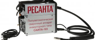
The number of connectors and controls on the front panel speaks volumes about the capabilities of the welding inverter
Inverter devices as the main equipment are widely used to perform the following technological operations:
- electric arc welding with consumable and non-consumable electrodes;
- welding using semi-automatic and automatic technologies;
- plasma cutting, etc.
In addition, inverter machines are the most efficient type of equipment used for welding aluminum, stainless steel and other difficult-to-weld metals. Welding inverters, regardless of the features of their electrical circuit, allow you to obtain high-quality, reliable and neat welds made using any technology. At the same time, what is important is that the compact and not too heavy inverter machine, if necessary, can be easily moved at any time to the place where welding work will be performed.
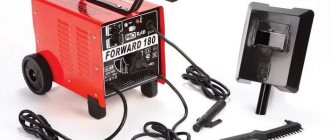
Mobility is one of the advantages of inverter devices
What does the design of a welding inverter include?
The welding inverter circuit, which determines its technical characteristics and functionality, includes such mandatory elements as:
- a unit that provides electrical power to the power part of the device (it consists of a rectifier, a capacitive filter and a nonlinear charging circuit);
- power part, made on the basis of a single-cycle converter (this part of the electrical circuit also includes a power transformer, a secondary rectifier and an output choke);
- power supply unit for elements of the low-current part of the electrical circuit of the inverter apparatus;
- PWM controller, which includes a current transformer and a load current sensor;
- a block responsible for thermal protection and control of cooling fans (this block of the circuit diagram includes inverter fans and temperature sensors);
- controls and indications.
How does a welding inverter work?
The formation of a high current, with the help of which an electric arc is created to melt the edges of the parts being joined and the filler material, is what any welding machine is designed for. For the same purposes, an inverter apparatus is also needed, which allows the generation of welding current with a wide range of characteristics.
In its simplest form, the principle of operation of the inverter looks like this.
- Alternating current with a frequency of 50 Hz from a regular electrical network is supplied to the rectifier, where it is converted into direct current.
- After the rectifier, the direct current is smoothed using a special filter.
- From the filter, direct current flows directly to the inverter, whose task is to convert it again into alternating current, but at a higher frequency.
- After this, using a transformer, the voltage of the alternating high-frequency current is reduced, which makes it possible to increase its strength.
Block diagram of an inverter type welding machine
In order to understand the importance of each element of the electrical circuit diagram of an inverter device, it is worth considering its operation in more detail.
Processes occurring in the electrical circuit of a welding inverter
The circuit of an inverter-type welding machine allows you to increase the current frequency from the standard 50 Hz to 60–80 kHz. Due to the fact that high-frequency current is subject to regulation at the output of such a device, compact transformers can be effectively used for this. An increase in the frequency of the current occurs in that part of the inverter electrical circuit where the circuit with powerful power transistors is located. As you know, only direct current is supplied to transistors, which is why a rectifier is needed at the input of the device.
Schematic diagram of the factory welding inverter "Resanta" (click to enlarge)
Inverter circuit from the German manufacturer FUBAG with a number of additional functions (click to enlarge)
An example of a circuit diagram of a welding inverter for self-production (click to enlarge)
The electrical circuit diagram of the inverter device consists of two main parts: the power section and the control circuit. The first element of the power section of the circuit is a diode bridge. The task of such a bridge is precisely to convert alternating current into direct current.
In the direct current converted from alternating current in the diode bridge, pulses may occur that need to be smoothed out. To do this, a filter consisting of capacitors of predominantly electrolytic type is installed after the diode bridge. It is important to know that the voltage that comes out of the diode bridge is approximately 1.4 times greater than its value at the input. When converting AC to DC, rectifier diodes become very hot, which can seriously affect their performance.
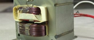
Components of a welding inverter using the example of a homemade machine
To protect them, as well as other elements of the rectifier from overheating, radiators are used in this part of the electrical circuit. In addition, a thermal fuse is installed on the diode bridge itself, the task of which is to turn off the power supply if the diode bridge has heated up to a temperature exceeding 80–90 degrees.
Read also: Continuity testing of three-phase electric motor windings
High-frequency interference generated during operation of the inverter device can enter the electrical network through its input. To prevent this from happening, an electromagnetic compatibility filter is installed in front of the rectifier block of the circuit. Such a filter consists of a choke and several capacitors.
Inverter power supply
The inverter itself, which converts direct current into alternating current, but with a much higher frequency, is assembled from transistors using an “oblique bridge” circuit. The switching frequency of transistors, due to which the alternating current is generated, can be tens or hundreds of kilohertz. The high-frequency alternating current thus obtained has a rectangular amplitude.
A voltage-reducing transformer installed behind the inverter unit allows you to obtain a current of sufficient strength at the output of the device so that you can effectively perform welding work with its help. In order to obtain direct current using an inverter apparatus, a powerful rectifier, also assembled on a diode bridge, is connected after the step-down transformer.
Transistors for the power module of the welding inverter
Varieties
Industrial three-phase devices come in three types: transformers, rectifiers, inverters and semi-automatic devices. Let's take a closer look at each of them.
Transformer
A 380 volt transformer is the simplest and classic type of welding equipment. Its basis is a transformer with three coils. Hence the name of this welding machine. Thanks to the use of three phases, the arc burns stably and the voltage practically does not change during welding. And the design of these machines is so simple that it allows you to repair the transformer literally “on the knee”, and without extra costs.
Transformers only supply alternating current, so you cannot use direct current in your work. This needs to be taken into account. Transformers are very bulky and heavy and require a cart to move them. But the price of such devices will please any professional.
Rectifier
A rectifier is the same transformer, only with one significant difference. A rectifier unit is built into its body (hence the name “rectifier”), which converts alternating current into direct current. This is their only difference. Such devices are more versatile than transformers, since they allow you to cook on any type of current.
Also, thanks to the rectifier, the arc burns more stable and is easier to ignite, including re-ignition. If you are a beginner, you have probably encountered difficulties in igniting the arc when using a transformer. The rectifier unit slightly, but simplifies this task. Otherwise, there are no differences between a rectifier and a transformer.
Inverter and semi-automatic
Semi-automatic welding and inverter are devices of a new generation. They are complex in design, have built-in microcircuits and additional functions. Their weight and dimensions are significantly smaller than those of a transformer or rectifier. But all the advantages come at a price. An inverter and semi-automatic device are significantly more expensive than other types of industrial devices.
The difference between an inverter and a semiautomatic device lies in the scope of application. The inverter's path is manual arc welding with electrodes. But the semi-automatic machine is used when welding using gas and filler wire. The semi-automatic machine has a filler material supply mechanism, which often operates in semi-automatic mode. Hence the name.
Inverter protection and control elements
Several elements in its circuit diagram allow you to avoid the influence of negative factors on the operation of the inverter.
To ensure that transistors that convert direct current into alternating current do not burn out during their operation, special damping (RC) circuits are used. All electrical circuit blocks that operate under heavy load and become very hot are not only provided with forced cooling, but are also connected to temperature sensors that turn off their power if their heating temperature exceeds a critical value.
Radiators and cooling fans take up significant space inside the inverter
Due to the fact that the filter capacitors, after being charged, can produce a high current, which can burn the inverter transistors, the device must be provided with a smooth start. For this purpose, stabilizers are used.
The circuit of any inverter has a PWM controller, which is responsible for controlling all elements of its electrical circuit. From the PWM controller, electrical signals are sent to a field-effect transistor, and from it to an isolation transformer, which simultaneously has two output windings. The PWM controller, through other elements of the electrical circuit, also supplies control signals to the power diodes and power transistors of the inverter unit. In order for the controller to effectively control all elements of the inverter's electrical circuit, it is also necessary to supply electrical signals to it.
To generate such signals, an operational amplifier is used, the input of which is supplied with the output current generated in the inverter. If the values of the latter diverge from the specified parameters, the operational amplifier generates a control signal to the controller. In addition, the operational amplifier receives signals from all protective circuits. This is necessary so that he can disconnect the inverter from the power supply at the moment when a critical situation arises in its electrical circuit.
Variations
Transformers, rectifiers, inverters and semi-automatic machines are all types of three-phase welding devices.
We will introduce you to each of them.
Transformer
The transformer (380V) is classified as a type of classic industrial welding equipment. This device received the name three-phase because of the three coils at its base.
Receiving three phases, which in turn ensures stable arc burning and voltage during the welding process. The simple design of the unit is easy to repair, and not expensive.
It must be taken into account that the transformer produces only alternating current. For this reason, you will not be able to use direct current in your work.
A trolley is used to transport the transformer; it is heavy and of impressive size. At the same time, it has a good price tag.
Rectifier
A rectifier is a type of industrial transformer, and it is distinguished by a built-in rectification unit. The unit is built into the housing, its function is to convert alternating current into direct current.
Since these devices allow you to cook on any type of current, they are more versatile than transformers. Due to the rectifier, the arc burns more stable and is easier to ignite, repeatedly.
Advantages and disadvantages of inverter-type welding machines
Inverter welding machines, which replaced the usual transformers, have a number of significant advantages.
- Thanks to a completely different approach to the formation and regulation of welding current, the weight of such devices is only 5–12 kg, while welding transformers weigh 18–35 kg.
- Inverters have very high efficiency (about 90%). This is explained by the fact that they spend significantly less excess energy on heating the components. Welding transformers, unlike inverter devices, get very hot.
- Due to such high efficiency, inverters consume 2 times less electrical energy than conventional transformers for welding.
- The high versatility of inverter machines is explained by the ability to regulate the welding current over a wide range with their help. Thanks to this, the same device can be used for welding parts made of different metals, as well as for welding using different technologies.
- Most modern inverter models are equipped with options that minimize the impact of welder errors on the technological process. Such options, in particular, include “Anti-stick” and “Arc Force” (fast ignition).
- Exceptional stability of the voltage supplied to the welding arc is ensured by the automatic elements of the inverter electrical circuit. In this case, automation not only takes into account and smoothes out differences in input voltage, but also corrects even such interference as the attenuation of the welding arc due to strong wind.
- Welding using inverter equipment can be performed with any type of electrode.
- Some models of modern welding inverters have a programming function, which allows you to accurately and quickly configure their modes when performing a certain type of work.
Like any complex technical devices, welding inverters have a number of disadvantages that you also need to be aware of.
- Inverters are highly expensive, 20–50% higher than the cost of conventional welding transformers.
- The most vulnerable and often failing elements of inverter devices are transistors, the cost of which can be up to 60% of the price of the entire device. Accordingly, repairing a welding inverter is quite an expensive undertaking.
- Due to the complexity of their electrical circuitry, inverters are not recommended for use in bad weather conditions and at low temperatures, which seriously limits their scope of application. In order to use such a device in field conditions, it is necessary to prepare a special closed and heated area.
When welding work performed using an inverter, long wires cannot be used, as they induce interference that negatively affects the operation of the device. For this reason, the wires for inverters are made quite short (about 2 meters), which makes welding work somewhat inconvenient.
Inverter welding is widespread due to the fact that the device is light in weight and dimensions. The operation of the inverter mechanism is based on the use of power switches and field-effect transistors. Such a useful device is sold in specialized stores. But you don’t have to spend money, but take the circuit diagram of an inverter welding machine and make it yourself. Here we’ll talk about how to do welding with your own hands at home and what you will need for this. The information will also be useful in the case of a purchased device, because thanks to the information provided in the article, you will not need to invite a specialist to repair it.
Manual arc welding technology
Domestic factories use high-performance and economical three-phase arc welding.
The development of this welding method has been carried out since 1934 by Dr. tech. Sciences G.P. Mikhailov in the welding laboratory of UPI named after. S. M. Kirov and in the workshops of the Uralmash plant.
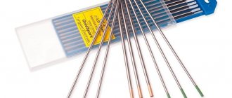
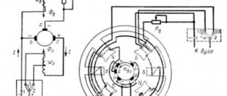
Manual welding with a three-phase arc is carried out according to the scheme shown in Fig. 62. In one special electrode holder, two parallel electrodes with high-quality coating or one electrode with two rods are fixed (Fig. 63). Two phases of welding current are supplied separately to the electrodes, the third phase is connected to the product. In three-phase welding, two arcs burn between the electrodes and the workpiece, and a third arc burns between the electrodes. The three-phase arc is ignited by touching the end of the electrodes to the surface of the work being welded.
Fig. 62. Scheme of three-phase arc welding
Fig. 63. Location of electrodes when welding fillet welds
Three-phase arc welding is applicable for butt and bead welds. Welding of T-joints, lap joints and corner joints should be carried out “in a boat”. When welding bead seams, the electrodes are arranged sequentially one after another in the direction of movement (Fig. 63). The arc should always be directed to the center of the corner; no transverse movements are made by the electrodes. The dimensions of the seam obtained in one pass depend on the diameter of the electrode used, the strength of the welding current and the speed of translational movement of the electrodes.
Recommended three-phase welding modes are given in table. 54.
Table 54. Three-phase arc welding modes
| Sheet thickness in mm | Electrode diameters in mm | Welding current strength in a | |
| on electrodes | for details | ||
| 5 | 4+4 | 100 | 100 |
| 10 | 5+5 | 180 | 180 |
| 14 | 5+5 | 200—250 | 200—250 |
| 25-30 | 6+6 | 300—320 | 300—320 |
| 30 and above | 8+8 | 380—400 | 350 |
The three-phase arc can be powered from a multi-station welding transformer or a special single-station three-phase transformer (Fig. 28, 29, 30). Can be used for. three-phase arc supply serial single-phase welding transformers, including three star or delta transformers. The installation operates stably according to an open delta diagram, consisting of two transformers and three regulators.
For three-phase arc welding, coated electrodes OMM-5, UONI-13, K-5 and others used for welding low-carbon steels are applicable.
The productivity of three-phase arc welding increases by 100-120%, the deposition rate increases up to 20%, and energy is saved by 15-20%. In this case, welded joints are obtained with high mechanical properties.
- Back
- Forward
Features of the inverter
An inverter welding machine is a power supply that is now used in computers. Electrical energy is converted in the inverter as follows:
- The AC voltage is converted to DC.
- The constant sine wave current is converted into alternating current at high frequency.
- Voltage values decrease.
- The current is rectified while maintaining the required frequency.
This welding inverter circuit allows you to reduce its weight and dimensions. It is known that old welding machines work on the principle of reducing the voltage and increasing the current on the secondary winding of the transformer. Due to the high current strength, it is possible to weld metals using the arc method. To increase the current and reduce the voltage on the secondary winding, the number of turns is reduced and the cross-section of the conductor is increased. As a result, a transformer-type welding machine weighs a lot and has significant dimensions.
To solve this problem, a welding inverter circuit was proposed. The principle is based on increasing the current frequency to 60 or all 80 kHz. Due to this, the weight is reduced and the dimensions of the device are reduced. To implement the plan, it was necessary to increase the frequency by thousands of times, which became possible thanks to field-effect transistors. The transistors communicate with each other at a frequency of approximately 60−80 kHz. Their power supply circuit is supplied with direct current, which is provided by a rectifier, which is used as a diode bridge. Voltage equalization is provided by capacitors.
The alternating current is transferred to the step-down transformer after passing through the transistors. In this case, a coil reduced by hundreds of times is used as a transformer. The coil is used because the frequency of the current supplied to the transformer is already increased a thousand times by the field effect transistors. As a result, similar data are obtained as when using transformer welding, but with a large difference in dimensions and weight.
Read also: What wire to use for grounding
Three-phase arc welding
Alternating current is transmitted to consumers through three wires, or, as they say, through three phases.
However, in practice, most AC consumers, such as conventional welding transformers, most electric motors, etc., are powered by only two phases. The third phase remains unused or all three phases are used differently. Uneven phase loads negatively affect the operation of current sources and the efficiency. When welding with a three-phase arc, the connection to the network is made simultaneously to three phases: two electrodes are connected to two, and the product being welded is connected to the third phase. With this connection of the electrodes, in contrast to the conventional arc welding method, three arcs burn: two between the electrodes and the product, and a third arc between the electrodes.
The third arc increases the rate of melting of the electrodes, due to which welding productivity increases by 100–120%, the deposition rate increases by 10–15% and, due to a more uniform phase load, cos increases from 0.3 to 0.75. Depending on the relative position of the electrodes and the part, there may be several three-phase arc welding schemes.
1st scheme. Welding with two electrodes located in two electrode holders. By changing the angle between the electrodes and their location relative to the work being welded, it is possible to obtain different penetration depths and bead widths. The disadvantage of this scheme is the presence of two electrode holders, which complicate the welding process.
2nd scheme. Welding with two parallel electrodes located in one specially designed electrode holder. The electrodes are insulated with each other by a thick layer of coating. Welding according to this scheme is simpler and more convenient.
3rd scheme. One electrode with a thick or high-quality coating is placed on the workpiece to be welded, the second electrode is fixed in a conventional single-phase electric holder.
4th scheme. Independent arc welding with three parallel electrodes. Each electrode is connected to one phase. The product is not included in the welding chain. This scheme, just like the second one, requires the manufacture of an electrode holder of a special design.
A three-phase arc is ignited by touching the surface of the workpiece being welded with the end of one of the electrodes. When welding with a three-phase arc, electrodes OMM-5, MEZ-04, UONI-13/45 and others are used, which are used to weld butt, tee, lap and corner joints.
To increase the productivity of three-phase arc welding, you can also use paired electrodes with an additional insert according to one of the options. Electrodes of this type also make it easier to extinguish the arc between the electrodes when the electrode is separated from the workpiece.
The disadvantages of three-phase arc welding include the difficulty of making welds located on a vertical plane or in a ceiling position, the rapid fatigue of the welder due to the large weight and size of the electrode holder, especially in the case of using large-diameter electrodes, the need to manufacture special, non-standard paired electrodes, the need for special three-phase transformers and necessary devices designed to quickly extinguish the arc between the electrodes.
Due to these disadvantages, manual three-phase arc welding has received limited use, mainly in factories when eliminating defects in steel castings and making fillet and butt welds of large cross-section in heavy metal structures.
Inverter assembly
To independently assemble inverter welding, you need to know that the circuit is designed first of all for a consuming voltage of 220 V and a current of 32 A. After energy conversion, the output current will increase almost eight times and reach 250 A. This value is enough to create a strong weld with an electrode up to a centimeter away. To make an inverter power supply you will need:
- Transformer with ferrite core.
- The primary winding of a transformer with a hundred turns of wire Ø0.3 mm.
- Three secondary windings: internal with 15 turns and Ø1 mm wire; medium with 15 turns and wire Ø0.2 mm; external with 20 turns and wire Ø0.35 mm.
Also, to assemble the transformer you need the following elements:
- fiberglass;
- copper wires;
- cotton material;
- electrical steel;
- textolite
Inverter welding circuit
The board containing the power supply is mounted separately from the power unit. The separator between the power supply and the power part is a metal sheet, which is electrically connected to the body of the unit. The gates are controlled using conductors that are soldered near the transistors. The conductors are connected to each other in pairs, and the size of their cross-section does not play a special role. However, it is important that the length of the conductors does not exceed 15 cm.
If you don’t have the skills to work with electronics, it’s better to contact a specialist. Otherwise, it will be difficult to understand the circuit of the welding machine .
Advantages
So, we now know that industrial welding machines are three-phase equipment. And this is their main characteristic, from which we will start when comparing an industrial device with other equipment.
To begin with, any three-phase device is automatically classified as professional equipment. Such welders can work continuously, their efficiency is close to 100%. But this cannot be achieved when using household or semi-professional devices. In some industries this advantage plays a major role. Because frequent interruptions in work are fraught with loss of profit.
Three-phase transformers and rectifiers are not sensitive to operating conditions. They may gather dust or be stored improperly, but they will still perform their task properly. Inverters and semi-automatic machines are more capricious in this regard due to the built-in microcircuits, but if they have a dust- and moisture-proof case, they can work in any conditions.
Experienced craftsmen will probably argue that an ordinary single-phase transformer is also unpretentious. And they will be right. Only the current pulsation frequency on a single-phase device is much higher, so the quality of the welds is noticeably worse. Compared to a three-phase transformer, of course.
Also, a standard stationary single-phase transformer or rectifier is not capable of welding metals of any thickness and using thick electrodes. But three-phase machines are truly universal and are used for welding of any level of complexity.
Step-by-step description of the assembly
Assembling the power supply . It is recommended to use 7×7 or 8×8 ferrite as the base of the transformer. The primary winding is constructed by winding wire along the width of the core. This improves the operation of the device during voltage surges. PEV-2 copper wires (wire) are used, and in the absence of a bus, the wires are connected into a bundle. The primary winding is insulated with fiberglass. After a layer of fiberglass, turns of shielding wires are wound on top.
Frame . This important element can be an old computer system unit, which has enough necessary holes for ventilation. An old 10-liter canister can be used, in which you can make holes and place coolers. To increase the strength of the structure, metal corners are placed from the body, secured with bolted connections.
Power part . The role of the power unit is played by a step-down transformer. Its cores can be of two types: W 20×208 2000 nm. There must be a gap between both elements, which is ensured using newsprint. When constructing a secondary winding, the turns are wound in several layers. Three layers of wires are laid on the secondary winding, and a fluoroplastic gasket is placed between them. A reinforced insulation layer is placed between the windings to avoid voltage breakdown on the secondary winding. The capacitor must have a voltage of at least 1000 V.
To ensure air circulation, an air gap is left between the windings. A current transformer is assembled on a ferrite core, which is connected to the circuit to the positive line. The core is wrapped with thermal paper , for which it is better to use cash register tape. Rectifier diodes are attached to an aluminum radiator plate. The diode outputs are connected with bare wires, the cross-section of which is 4 mm.
Inverter block . The main purpose of the inverter system is to convert direct current into alternating current at high frequency. To increase it, field-effect transistors are used that operate to close and open at high frequencies. It is recommended to use not one powerful transistor, but to implement a circuit based on two less powerful ones. This is necessary to stabilize the current frequency. The circuit must contain capacitors connected in series.
Cooling system . Cooling fans are installed on the case wall, for which computer coolers can be used. They are necessary for cooling the working elements. The more of them used, the better. Two fans must be installed to blow the secondary transformer. One cooler blows air over the radiator, thereby preventing overheating of the working elements - rectifier diodes.
It is worth using an auxiliary element - a temperature sensor, which is recommended to be installed on the heating element. The sensor is triggered when the critical heating temperature of any element is reached. After it is triggered, the power to the device is turned off.
During operation, inverter welding heats up quickly, so there must be two powerful coolers. These coolers or fans are placed on the device body to work to extract air. Fresh air enters the system through openings in the housing. The system unit already has these holes, and when using any other material, do not forget to ensure the flow of fresh air.
Soldering the board . A key factor, because the circuit is based on a board. It is important to mount the transistors and diodes on it opposite each other. A board is mounted between the cooling radiators, through which the circuit of electrical appliances is connected. The supply circuit for 300 V voltage is calculated. The additional arrangement of 0.15 µF capacitors allows excess power to be dumped back into the circuit. At the output of the transformer, capacitors and snubbers are placed, with the help of which the overvoltage at the output of the secondary winding is suppressed.
Setting up, debugging . After assembling the inverter welding, a number of procedures are required, in particular, setting up the operation. To do this, you need to connect 15 V voltage to the PWM (pulse width modulator) and power the cooler. Additionally, a relay is included in the circuit through resistor R11. The relay is included in the circuit to avoid voltage surges in the 220 V network. It is important to check that the relay is turned on and then apply power to the PWM. The result should be a picture where the rectangular areas in the PWM diagram should disappear.
The correct connection can be judged if, when configured, the relay outputs 150 mA. If the signal is weak, the boards are not connected correctly. Perhaps one of the windings is broken. To eliminate interference, all power supply wires are shortened.
Functionality check
After assembly and debugging work, the functionality of the welding machine is checked. To do this, the device must be powered from a 220 V power supply, then set high current values and check the indicators with an oscilloscope. In the lower loop, the voltage should be within 500 V and no more than 550 V. If everything is correct and the electronics are selected strictly, the voltage indicator will not exceed 350 V.
Then the welding is checked in action. For this purpose, the necessary electrodes are used, and the seam is cut until the electrode burns out completely. It is then important to monitor the temperature of the transformer. If it simply boils, it means that there are shortcomings in the scheme and it is better not to continue the work.
After cutting two or three seams, the radiators will become very hot, and it is important to let them cool down. A two to three minute pause is enough for this; eventually the temperature will level out to the optimum.
How to use the device
After connecting the homemade device to the circuit, the controller automatically sets a certain current strength. If the wire voltage is less than 100 V, then the device is faulty. You will have to disassemble the device and re-check the correct assembly . Using this type of welding machine, both ferrous and non-ferrous metals are soldered. To assemble a welding machine, you will need knowledge of the basics of electrical engineering and, of course, free time to make it.
Inverter welding is indispensable in the garage. If you haven’t acquired this tool yet, make it yourself and use it for your pleasure!
Nuances of connection and selection
Before connecting a 380 V welding unit, you need to consider a number of features. Three-phase welders come with four and sometimes five pins. Please pay attention to this when purchasing a power cable for a welding machine.
In cases where the production does not have sockets of the required voltage, or the work is carried out on site, you need to think in advance about how to connect a three-phase device to a generator or substation.
When choosing an industrial three-phase welding machine, you should choose universal equipment that operates in different modes, such as RDS and MMA (or MIG/MAG).
Using such devices, you can carry out welding work of any complexity, whether in a shielding gas environment, or using only electrodes.
If at home welding it is possible to connect to a 380 volt network, we advise you to acquire a three-phase welding machine.
Because it does not cause overvoltage and power outages, evenly distributing the load on the network, and working much more stable than single-phase ones.