Specifications
Main characteristics of the IT-1M lathe:
- The maximum diameter of the workpiece depends on the location: directly above the bed - 400, above the recess - 550, above the support - 225.
- In the recess, the maximum processing length is 30 cm.
- The diameter of the rod passing into the spindle hole is 36 mm.
- The number of gears to switch spindle speeds is 12.
- The workpiece length limit is 140 cm.
The machine provides rotation in forward and reverse directions. The main drive of the unit has a power of 3 kW and a rated speed of 1410 rpm. Processing accuracy is normal (N).
Purpose and scope
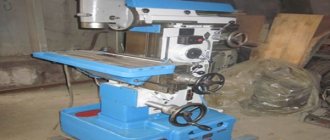
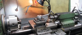
The IT-1M screw-cutting lathe is used in small enterprises, home workshops and workshops. With the standard configuration, it performs all classic turning processes, but can also work with advanced functionality. Work with the product is carried out in a chuck, in a faceplate, and also when secured to centers.
This unit is used in small industries, but at the same time meets all the requirements for professional equipment. The machine is reliable and requires minimal maintenance costs. As standard, it performs the following functions:
- boring holes;
- drilling and turning surfaces;
- thread cutting;
- processing the edges of the workpiece, including turning the ends.
If you use additional tools or equipment on the unit, the functionality expands significantly. The master can carry out milling operations, grinding, boring of cabinet products of limited sizes.
Areas of application of machines
Using a machine of this model, turning operations can be performed while securing the workpiece in the faceplate, equipment chuck and in its centers. This machine has a lightweight design (total weight 1140 kg), which determined the main area of its use: small repair shops, often of a mobile type.
What’s convenient is that if you install special devices on the IT-1M lathe, you can also perform individual milling operations on it. In particular, on such a machine it is possible to process various grooves and planes, carry out internal and external grinding, and boring oversized body parts. IT-1M in its standard configuration can be used to perform the following technological operations:
- boring;
- turning;
- drilling holes;
- facing operations.
The screw-cutting lathe of this model, in accordance with the requirements of the state standard (8-82E), is assigned an accuracy class of “H”. All sources of electrical consumption of this machine are supplied with voltage from a generator that drives a traditional automobile engine.
IT-1M has certain design features. These, in particular, include:
- the guides along which the working elements of the machine move have a prismatic configuration; they have previously been subjected to heat treatment and polished;
- the bed of this lathe is made by casting, it has a box-shaped shape, and for greater rigidity it is equipped with transverse ribs;
- spindle rotation can be carried out in one of 12 possible modes;
- the main mechanisms of the machine are located in the headstock: spindle unit, feed box, gear block, feed reverse mechanism, unit for changing the pitch of the thread being cut, etc.;
- the movement of the tailstock of a screw-cutting lathe of this model is carried out due to special guides attached to its frame;
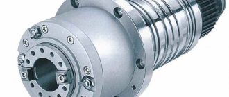
- rotation and precise positioning of the spindle is ensured by two supports, one of which (rear) rotates on ball-type bearings, and the second (front) rotates on double-row roller bearings with adjustable radial clearance;
- a plunger pump, which ensures lubrication of all components of the IT-1M machine, is located on the front part of the headstock;
- the movement of the feed box elements is carried out due to the drive located in the headstock of this equipment, which makes it possible to use such equipment for producing threads;
- the tailstock of the machine has the ability to move in a direction perpendicular to the axis of the workpiece, which makes it possible to turn conical surfaces on such equipment;
- If, when processing individual parts, the chuck's jaws protrude beyond its outer diameter, then a special guard is used, which is secured using clamping mechanisms.
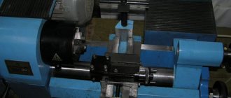
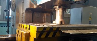
Low longitudinal feed with tool holder
Design features of the device
The main design elements of the unit in question:
- feed box assembly;
- persistent stand;
- spindle head;
- electrical equipment;
- cartridge stopper;
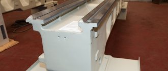
- cast iron frame;
- cooling system with separate motor;
- apron;
- caliper;
- hilum;
- gearbox with handles on the front panel to switch the spindle speed range.
The system also has an electrical cabinet that protects the unit from short circuits and overloads.
Main components
If we talk about the composition of this lathe, then it includes such main components as:
- cabinets;
- mechanisms to ensure cartridge obstruction;
- apron;
- gearbox;
- unit for providing lubrication;
- pasterns (back and front);
- a cabinet containing electrical equipment;
- gearbox;
- control Panel;
- bed;
- caliper
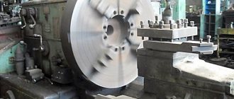
Caliper
Due to its overall dimensions (2160*1500*960 mm), the machine has the ability to work with parts up to 1400 mm in length.
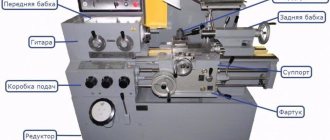
Location and operating features of controls
Most of the machine's controls are located on its headstock.
Main components
On top of the headstock there is a panel with a toggle switch. Below is a handle for selecting the spindle speed. Above it there are 3 knobs responsible for the pitch and type of thread, as well as the feed amount. To the right of the lower lever there is a handle for controlling the rotation of the spindle.
Directly below the toggle switch panel there is a thread type selection lever and a selection knob.
There are fewer levers to control the tailstock:
- lever to operate the quill;
- lever for clamping it.
On the apron of the machine there is a handwheel for positioning the support and carriage, as well as a handle for positioning the cross slide and a handle for the running nut.
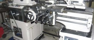
Spindle
The spindle has 12 rotation speeds. The end of the spindle is flanged, the end of the spindle complies with the standard 12593-6K.
The rotation speed range in any of the available directions is 18-250 rpm.
Electrical diagram
To power the machine's electric motors, three-phase voltages of 380 and 220 V are used.
Main components of the electrical circuit:
- main electric motor;
- circuit breaker;
- main engine reverse switch;
- package switch for engine and cooling system;
- pump switch and cooling system motor.
Kinetic scheme
Electrical equipment
The IT-1M package includes two asynchronous electric motors with three phases:
- Main propulsion engine.
- Cooling pump motor.
This machine uses the following AC current values:
- Power circuit - from 3 to 50 Hz, 220-380 V.
- The circuit for local lighting usually uses a 12 V on-board electrical circuit.
In this equipment, in the left cabinet there is an electrical input for the supply wiring. The input wires use the PVG brand with a cross-section of 2.5 square millimeters. Along with this wire there is an output wire to the main movement motor and a ShR32P8EG2 plug connector for connecting a grinding tool.
At the top of the headstock there is a control panel on which handles are located for switching operations:
- Automatic switch (QF) with electromagnetic release for on/off. Equipment from the network.
- Packet cam switch (SA2). It is designed to select the voltage of the main movement motor.
- Packet cam switch (SA4). It is necessary to select the cooling pump motor voltage and plug connector.
- Toggle switch (SA4) for the cooling pump motor.
At the rear there is a box with a package switch (SA1) that turns on and reverses the main movement engine.
The toggle switch (SA5) is located on a flexible lighting stand, on the lamp itself.
All necessary electrical diagrams can be found in the machine manual.
Advice: Operation of electric motors requires systematic inspection of motors for serviceability at least once every two months. To prevent proper operation of engines, it is important to clean them externally and internally, as well as to lubricate the operating bearings.
Operating instructions, passport
The operating instructions for this unit traditionally include instructions for setting up the equipment, its installation, commissioning and use. There are also all the diagrams and drawings that relate to the IT-1M screw-cutting lathe. Basic operating rules:
- Before turning on the machine, check the grounding.
- Check the lubrication system and the headstock oil seal.
- At the first stage, the unit is turned on at idle speed without using the working parts.
- Then all working parts of the machine are sequentially launched for testing.
- Before starting work, the machine must be idling for at least 5 minutes.
After passing the initial check, stop the main drive and adjust the machine parameters for the current operation.
You can download the lathe's passport for free from the link IT-1M lathe's passport
Rules and safety precautions
When working with the machine, precautions must be taken to avoid injury. Basic safety rules:
- work on a machine with special clothing and glasses;
- the machine must stand on a hard surface that prevents vibration;
- Be sure to follow fire safety rules.
When working with a lathe, do not allow sagging parts of clothing. Hair must be strictly under the headdress.
How to save on machine parts without harming production
Sometimes it happens that spare parts for drilling machines and other categories of units are purchased with a greater resource than required by the procurement regulations. In this case, the full potential of the components will simply be unclaimed. Provided that the full resource has not been exhausted, it is possible to install an engine of much lower power to reduce wear rates
It is important to maintain correspondence between the nodes. Reduced power will make it possible to save money on system repairs, since they will be under much less load
This will often be irrelevant with the mechanical part, since the design of the machine may not allow changing important elements.
Spindle problems and repair features
The spindle is a rather expensive part, and therefore it is necessary to change it in extreme cases. In most cases it is easier to repair.
- If the neck wears out, it must be sharpened and polished using GOI paste.
- Checking the dimensions of the cone is carried out after sanding and grinding. A special caliber is used.
- If the shape of the seat is incorrect, which most often occurs due to lack of regular cleaning, you should bore the seat for an adapter sleeve in which a standard cone is formed.
Before boring, it is imperative to run in the bearings. They are tightened, runout is checked, and then compliance with accuracy standards according to GOST.
The IT-1M lathe is a reliable piece of equipment with a high level of performance. They are successfully used in home workshops and small workshops. The standard equipment performs all basic turning functions; when additional equipment is added, the functionality of the machine is significantly expanded.
Caliper
The technical characteristics of this element are determined by the design, which consists of:
- top carriage;
- a sled for performing movements;
- a unit securing a cutter having a rotating design.
The rotation and locking action of the unit to secure the cutter is carried out using one handle.
What is also interesting is that the movement of the caliper in different directions is carried out by a special mechanism located in the apron of the lathe. This mechanism converts the rotation of the lead screw into the movement of the caliper.
The machine also uses quite effective protection that locks the handle of the running shaft during its startup, which protects the operator from unpleasant consequences.
Lubrication system
The IT-1M machine uses a special lubrication system, which includes the following elements:
- filter;
- magnetic cartridge;
- oil pump;
- oil reservoir.
To supply lubricating fluid, a special pump is used, powered by the rotating gearbox shaft, regardless of the direction of its rotation.