A gate valve is a type of pipeline fitting in which the shut-off element moves perpendicular to the direction of flow of the pipeline working fluid. The main materials for its manufacture are steel, which makes it possible to obtain the highest technical characteristics; when installing large-sized structures, you should know the weight of steel valves, the table of values \u200b\u200bof which is indicated in the standards.
In large-diameter pipelines, the weight of the valve together with the drive can reach one and a half tons. To transport, lift and install it, you will need special equipment, the carrying capacity of which must correspond to the weight of the product, determined by the corresponding tabular indicators.
Fig.1 Valves of pipeline systems in operation
Weight of steel valves - table of overall dimensions and weight
The dimensional and weight parameters of the valves must comply with GOST 9698-86, which applies to models with a heating limit of the passing medium up to +565º C. The nominal diameter dy is regulated by the given standard and lies within the range of 15 - 2000 mm, the permissible pressure range is 1.6 - 250 bar.(atm.)
Valves are manufactured with manual control, with the exception of massive and remote units of long highways. In such cases, the valves are equipped with electrical and hydraulic controls; standards allow the use of a pneumatic drive.
Marking
The symbol for fittings consists of the following alphabetic and digital symbols (let’s look at the example of a sample marked 30s964nzh):
1 - designation of the type of element, in our case the number 30 (maybe 31) - valve;
2 - the main material for the manufacture of the body, s - steel (steel), the most common grades are LS (alloy steel), nzh - corrosion-resistant alloys with the addition of chromium, h - ordinary gray cast iron, br - non-ferrous metals (brass or bronze);
3 - type of drive mechanism of the locking element, numbers 3,4,5 mean manual control using a flywheel, 6 - pneumatic, 7 hydraulic, 8,9 - electric drive;
4 — model serial number;
5 — material of the valve or its sealing surface in the case of applying anti-corrosion stainless alloys, rubber and other sealants to the part.
Fig.2 Marking
Classes and markings of building reinforcement
The use of reinforcement in construction is carried out in accordance with the requirements that are determined structurally. Specialists calculate structures and accept rods with markings containing the necessary information about the reinforcing product.
Classes are a designation of parameters not of the rod itself, but of the steel from which it is made. Based on this criterion, construction reinforcement is conventionally divided into 3 classes:
- A – grade of ordinary hot-rolled or cold-drawn rod steel;
- At – heat-treated (reinforced) steel;
- Ac - steel can be assembled into a frame by welding;
- Ak – corrosion-resistant with a protective coating (galvanized or galvanized).
The designation of hot-rolled rod reinforcement contains a digital index. General marking contains some properties of metal products:
| Strength class | Diameter | Steel for manufacturing | Description |
| AI (A240)* | 4…40 | Carbon St3KP, St3PS, St3SP | Smooth rod |
| A-II (A300) | 10…80 | Low alloy St1G2 or carbon St5SP | Corrugated rod or wire in coils |
| A-III (A400) | 6…40 | Alloyed 35GS, 25G2S, 32G2R | Ribbed for foundation |
| A-IV (A600) | 6…40 | Low alloy cold rolled 80С, 20ХГ2Ц | Corrugated Crescent Reinforcement |
| AV (A800) | 6…40 | Low alloy 23Х2Г2Т | Ribbed Rods |
| A-VI (A-1000) | 6…32 | Low alloy 22Kh2GAYu, 22Kh2G2R, 20Kh2G2SR | Corrugated blanks for welding |
* designation/marking of old and new samples.
What metal are valves made from?
GOST 9698-86 regulates the three main metals for casting housings - steel, cast iron and non-ferrous alloys, while housing steel can withstand a maximum pressure of up to 250 bar and a temperature of + 565º C, exceeding similar indicators for cast iron and non-ferrous metals. Steel valves have a maximum channel passage of 1600 mm, and the highest weight indicators of the fittings - the weight of a valve with an electric drive can reach 15,000 kg.
As can be seen from the table (Fig. 3), for the production of parts they use foundry (letter L at the end of the designation) 20L, 25L and structural steels (09G2S), stainless high-alloy alloys for castings (12Х18Н9ТЛ, 12Х18Н12М3ТЛ).
Non-alloy steels 20L, 25L are used for casting engineering parts; they can be welded without restrictions and are designed for operating conditions from -40 to +450º C.
Alloyed silicon-manganese steel. 09G2S is intended for welded structures and is designed for operation under pressure in a temperature range from -70 to +425º C.
Anti-corrosion steel of the austenitic class 12Х18Н9ТЛ belongs to components with special characteristics, its heat resistance (resistance to oxidation in a gas environment) reaches +750º C, and heat resistance (ability to work under load for a long time at high temperatures) reaches +600º C.
Rice. 3 Materials for the manufacture of valves designed for different operating conditions (example)
Art. 12Х18Н12М3ТЛ, like the previous sample, has good anti-corrosion properties, directly related to the percentage of chromium in the composition (X18 marking symbols indicate a chromium content of 16-20%), is used for castings and has special properties. Corrosion-resistant steel of the austenitic class 12Х18Н12М3ТЛ is heat-resistant (capable of operating under load at +800º C) and is designed for operation in boiling acids (phosphoric, formic, acetic and others).
All stainless steels are weldable to a limited extent, that is, they require preheating to 100 - 120º C, and after welding - further heat treatment.
The locking wedges or disks of the valves are made of alloys similar to the materials of the housings; subsequently, high-strength corrosion-resistant compounds are fused onto them (applied by automatic welding).
Fig.4 Weight of steel valves according to GOST 9698-86
Kinds
GOST 5762-2002 classifies valves according to many design features, the main ones:
- Shutter type. There are two dominant designs for the locking assembly - wedge-shaped (elastic, rigid and composite wedge), in which the seat holes are located at an angle to the central axis of the passage channel, and the locking part has a conical shape. The second type of valve is parallel, in which the valve closes the channel perpendicular to the flow (gate, single-disk, double-disk valve).
- Type of pipe connection. The main method of connecting to pipes is flange; for small sizes, threaded coupling fasteners are used. For parts of large dimensions and weight, welding is used; pin and union types of connection are less common.
- Types of movable rod seals: stuffing box, bellows, graphite-reinforced, liquid metal and others.
- Type of seal on the valve. If the valve is coated with various polymers, the seal is called elastic; in their absence, the type of sealing is metal to metal.
- The type of force transmission to the lock is rotary and translational drive.
- The design of the flow channel is with full and incomplete passage.
- By type of drive - mechanical, electric, hydraulic and pneumatic.
- The connection between the body and the cover is either cast flanges or without flanges.
Rice. 6 Pin and union connections
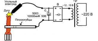
How to properly measure corrugated reinforcement
In order to accurately measure the diameter of corrugated reinforcement, for example class A500C, you should use a caliper, and measure according to the “groove-edge” principle, this is required.
- Determine the diameter of the “body” of the rod (D min).
- Measure the size along the edge (D max).
- Add the resulting values and divide by two - you will get a result as close as possible to the nominal result.
Connection with pipes
In water supply and wastewater systems, the main method of inserting valves into a pipeline is a flange connection with bolts (studs) and nuts, with rubber gaskets installed between the parts. The valve can have pin ends (with pipe or metric threads) and fitting ends - this type of fastener is used when installing floating craft, ships and vessels into pipelines.
Almost all samples of steel locking fittings, in addition to coupling fasteners, are designed for welding - unalloyed and structural carbon steel, from which body blanks are cast, has weldability without restrictions.
Cast iron is very difficult to weld, so all cast iron fittings for heating systems, water supply, gas and oil products have only a flanged type of connection to the main line.
Non-ferrous metals and anti-corrosion stainless steels are welded using special electrodes and modes using sophisticated equipment, which makes it difficult to carry out external installation by welding. Therefore, the main method of connecting corrosion-resistant fittings to pipes is flanges; for small passage dimensions, fasteners using threaded couplings are used.
Rice. 7 Wedge gate valve
Related article:
Gate valve - scope of application, design, popular brands . The article describes in detail about gate valves, where they are used, characteristics and standard sizes, as well as how to install and operate. It might be interesting to read.
Main purpose
Construction mounting fittings are intended for the manufacture of frame products to strengthen concrete used for the construction of objects for various purposes. As a rule, these are periodic profile rods with different diameters.
Volumetric and flat frames are calculated structurally. They are made from individual rods by welding or wire tying.
The need to use reinforcement in reinforced concrete structures is due to the weakness of concrete to bending and compression. Such loads are experienced by floor slabs, wall and foundation blocks, lintels and other structural elements. Without reinforcement, products crack and collapse. The frame solves the problem - rigid reinforcement works in tension and compensates for the destructive stress in the concrete. Moreover, the frames are necessarily located in the lower stretched part, where the maximum deformation force occurs, as well as throughout the entire volume to stabilize and redistribute the load.
Common brands of valves - design features and scope of application
Gate valves are used as stops to block the flow of passing media - water, steam, natural gas, petroleum products, explosive, aggressive, toxic and flammable substances that do not have a negative chemical and physical effect on the structure of their surface.
The most commonly used are wedge types, the seats of which are made with surfacing from anti-corrosion alloys with a high chromium content, or from a heavy-duty alloy based on cobalt and chromium with the addition of tungsten or molybdenum (stellite). High-strength, corrosion-resistant alloys are deposited onto the wedge surface and seat holes inside the body casting; separate welded seat O-rings are often used, which are screwed or welded into the passage.
30s41nzh
A wedge lock with a flange and flywheel control is installed on pipeline lines transporting water, steam, petrochemical products, and natural gas. Its body is made of st. 25L, the rod and wedge welding are welded from anti-corrosion alloy 20Х13, the gland seal is TRG graphite rings.
Modification 30s41nzh is used in the range from -40 to +450º C and a pressure of 16 atm., The internal diameter ranges from 50 to 600 mm.
The product is designed for a service life of at least 10 years outdoors in a temperate climate with temperature changes from -45 to +45º C. (climatic version U1).
Rice. 9 30s915nzh and 30s15nzh – structural device
Assortment of fittings
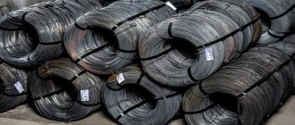
GOST 5781-82 contains a conditional range of frame reinforcement (Table 1):
| Profile number (nominal rod diameter dн) | Cross-sectional area of the rod, cm2 | Weight of 1 m profile | |
| Theoretical; kg | Maximum deviation, % | ||
| 6 | 0,283 | 0,222 | +9,0 |
| 8 | 0,503 | 0,395 | -7,0 |
| 10 | 0785 | 0,617 | +5,0 |
| 12 | 1,131 | 0,888 | -6,0 |
| 14 | 1,540 | 1,210 | |
| 16 | 2,010 | 1,580 | |
| 18 | 2,540 | 2,000 | |
| 20 | 3,140 | 2,470 | +3,0 |
| 22 | 3,800 | 2,980 | -5,0 |
| 25 | 4,910 | 3,850 | |
| 28 | 6,160 | 4,830 | |
| 32 | 8,010 | 6,310 | |
| 36 | 10,180 | 7,990 | +3,0 |
| 40 | 12,570 | 9,870 | -4,0 |
| 45 | 15,000 | 12,480 | |
| 50 | 19,630 | 15,410 | |
| 55 | 23,760 | 18,650 | +2,0 |
| 60 | 28,270 | 22,190 | -4,0 |
| 70 | 38,480 | 30,210 | |
| 80 | 50,270 | 39,460 | |
The theoretical mass of products may vary - it depends on the brand of alloy used and has an error, usually within the specified range.
Calculator
Reinforcement weight © metcalc.ru
30s915nzh
Wedge-shaped electric drive valve 30s915nzh with a flange and a sliding spindle is designed to work as a locking device in pipeline lines with substances that are not aggressive to the surface of its parts (steam, ammonia, oil, natural gas, petroleum products), the corrosion rate of which does not exceed 0.1 mm . in year.
The body is cast from steel. L25 or L35, the wedge and rod are made of stainless steel 20Х13, the welding on the sealing rings is alloys 07Х25Н13, 04Х19Н9С2, on the wedge - 13Х25Т, the stuffing box is TRG.
The operating temperature of the unit does not go beyond -40 - +450º C, the nominal pressure is 40 atm. for climatic version U1, channel size 50 - 400 mm.
The main technical characteristics of 30s15nzh are similar to 30s915nzh, the valve fittings have connecting flanges, a retractable rod and manual control using a handwheel, the internal passage does not extend beyond the boundaries of 50 - 350 mm.
Rice. Design and weight of steel valves 10 30s927nzh
Examples of calculating reinforcement consumption
As mentioned above, the number of rods required for reinforcement depends on the type of structure; below are examples of how to carry out calculations for them.
Strip foundation
Let's calculate the amount of reinforcement per 1 m3 of concrete required to reinforce a strip foundation - height 1.2 m, width 0.4 m. For longitudinal reinforcement we use steel rods with a diameter of 12 mm - 14 pcs., for transverse reinforcement, clamps from 8 mm rods - step 30 cm, as well as connecting rods in 60 cm increments.
An example of a reinforcement scheme for a strip foundation.
The procedure for calculating flow according to the diagram above:
- We calculate the cross-sectional area of concrete: 120*40=4800 cm2.
- Sectional area of longitudinal reinforcement: 14*1.131=15.834 cm2.
- We find the percentage of content of longitudinal rods in concrete: 15.834/4800*100=0.329875%, rounded to 0.33%.
- Using the consumption table, we convert the percentages into kg, for this: 0.33/0.1*7.85=25.905 kg.
- To make one clamp, you need 3 m of rod with a thickness of 8 mm (weight of 1 meter is 0.395 kg), in total 7 clamps will be needed for 1 m3 of foundation, and this is: 7 * 0.395 = 2.765 kg.
- You will also need 4 connecting rods with a length of 50 cm and a diameter of 8 mm, in total: 4 * 0.5 * 0.395 = 0.79 kg.
- For 1 m3 of strip foundation concrete with such reinforcement, we get a total of: 25.905 + 2.765 + 0.79 = 29.46 kg of reinforcement.
So, by calculating the required volume of concrete and the number of rods per 1 m3, you can find out how many tons of steel are needed to reinforce the entire foundation. But you should also take into account the number and size of reinforcement overlaps, and calculate the number of additional elements to reinforce corners and other elements.
Monolithic floor slab
Let's calculate using the example of reinforcing a 20 cm thick floor slab, since this is the most common size. The pitch of the reinforcing mesh is 200 by 200 mm, the diameter of the rod is 10 mm, the reinforcement is 14 mm - the pitch is 200 mm.
Schematic example of floor reinforcement.
The procedure for calculating consumption per 1 m3 of flooring according to the scheme:
- For 1 m2 of slab, 20 m of reinforcement is required to knit the upper and lower layers of the mesh.
- 1 m3 of concrete occupies an area of 5 m2, therefore: 5 * 20 = 100 meters - consumption of the rod for knitting the mesh.
- The weight of a meter of 10 mm reinforcement is 0.617 kg. We get, 100*0.617=61.7 kg, the consumption of longitudinal rods for constructing the mesh.
- For additional reinforcements, you will need about 50 meters of a rod with a diameter of 14 mm, total: 50 * 1.21 = 60.5 kg.
- Additional slab elements (space frames, “U” shaped elements), about 20 m of 10 mm steel rods are required, total: 20 * 0.617 = 12.34 kg.
- Total consumption: 61.7 + 60.5 + 12.34 = 134.54 kg of reinforcement per 1 m3 of concrete for a monolithic floor slab.
Thus, it is possible to make calculations for floors of various structures. But at the same time, one should also take into account the cost of joints, reinforcements in the pushing zone, and other additional elements, depending on the shape and features of the structure.
Reinforced concrete column
Let's calculate the consumption for reinforcing a column 300 by 300 mm. Longitudinal reinforcement class A500C with a diameter of 16 mm - 4 pcs., transverse reinforcement A240 - 8 mm. Calculation procedure:
- We calculate the cross-sectional area of the column: 30*30=900 cm2.
- The cross-sectional area of the reinforcement is: 4*2.01=8.04 cm2.
- We calculate the percentage of content of longitudinal rods in concrete: 8.04/900*100= 0.893%.
- We convert the percentages into kg, for this: 0.893/0.1*7.85= 70.1 kg.
- With this cross-section, 1 m3 of concrete in length is 11 meters of column.
- An 11 meter column with a pitch of 25 cm will require about 45 clamps.
- 1 clamp takes 1 meter of rod with a diameter of 8 mm weighing 0.395 kg, which means a total of 45 * 0.395 = 17.775 kg per cube.
- In total, a cube of column concrete will require 70.1 + 17.775 = 87.875 kg of reinforcement.
All calculations for steel consumption are theoretical; each case should be approached individually, taking into account all the existing loads on the structure, since the minimum percentage of reinforcement depends on this, and on it, how much reinforcement will be needed per 1 m3 of concrete. If you have any questions, ask in the comments, we will be happy to help.
30s927nzh
An electric drive analogue of the model discussed above - 30s927nzh with a flange and a non-retractable spindle, is used as a shut-off element in the mains of water supply systems, to block the flow of liquids and gases that are not aggressive to common metal alloys.
The body and wedge 30s927nzh are made of st. 25L, 35L and stainless steel 20X13. The temperature range of 30s927nzh is -40 - +300 C., pressure is 25 bar., the product has a flange connection with dimensions regulated by GOST R 54432 2011 (version B row 1), channel diameter - from 300 to 1000 mm.
30s941nzh
Wedge-shaped steel gate valve with electric drive 30s941nzh is used for remote control of the flow of non-aggressive working fluid in pipeline systems of public utilities and oil and gas complexes.
For connection to the main line, cast flanges are used, made in accordance with GOST 12815 - 80. Class A tightness is ensured by a graphlex packing. The body, cover and wedge are cast from steel. 25L, 35L (20GL, 25KhGSL), the spindle is made of stainless steel 20Х13 (14Х17Н2), surfacing on the rings and wedge is made of 07Х25Н13 (12ХН10Т,08Х17Т1).
Rice. 11 Device weight of steel valves 30s941nzh
The operating temperature range is from -40 to +425º C, the nominal pressure is 16 bar, the connecting dimensions range from 50 to 800 mm, the service life is at least 5 years.
In a similar electric drive product 30нж941нж with passage diameters from 50 to 1000 mm. The body is made of steel 12Х18Н9ТЛ, the operating temperature range of which is from -60 to +560º C.
Technical characteristics of construction reinforcement
GOST 5781-82 defines the basic technical requirements for fittings of each class (Table 8):
| Steel grade | Yield strength st | Temporary tensile strength sв | Relative elongation d5,% | Uniform elongation dr, % | Impact strength at -60 °C | Bend and cold test | |||
| N/mm2 | kgf/mm2 | N/mm2 | kgf/mm2 | MJ/m2 | kgf m/cm2 | ||||
| No less | |||||||||
| AI (A240)* | 235 | 24 | 373 | 38 | 25 | — | — | — | 180°; c = d** |
| A-II (A300) | 295 | 30 | 490 | 50 | 19 | — | — | — | 180°; c = 3d |
| Ac-II (Ac300) | 295 | 30 | 441 | 45 | 25 | — | 0,5 | 5 | 180°; c = d |
| A-III(A400) | 390 | 40 | 590 | 60 | 14 | — | — | — | 90°; c = 3d |
| A-IV(A600) | 590 | 60 | 883 | 90 | 6 | 2 | — | — | 45°; c = 5d |
| AV (A800) | 785 | 80 | 1030 | 105 | 7 | 2 | — | — | 45°; c = 5d |
| A-VI (A1000) | 980 | 100 | 1230 | 125 | 6 | 2 | — | — | 45°; c = 5d |
**с – sending thickness, d – rod diameter.
The construction length of the rods according to GOST is from 6 to 12 meters. The document also regulates the composition of steels for the manufacture of building rods and their other properties.
To make it easier to distinguish between the rods, their ends are painted in different colors:
- A-IV – red;
- AV – red and green;
- A-VI – red and blue.
30s964nzh
The electric drive model with a retractable spindle 30s964nzh is designed for operation at temperatures from -40 to +450º C, at a nominal pressure of 25 bar. 30s964nzh is made in a case made of st. 25L with surfacing of seat rings and wedge with alloy 20Х13, packing of the stuffing box - thermally expanded graphite TRG. Standard passage from 50 to 1000 mm, connection with flanges according to the standard corresponding to GOST R 54432 2011 (version B row 1).
Rice. 12 Design and weight of steel valves 30s964nzh
Among the variety of main valves, wedge valves are most widely used in the oil and gas and chemical industries, to stop the transportation of chemicals, oil and its products, and in public utilities to shut off the supply of water, steam and gas.
To increase the service life, physical and chemical parameters, fusion on the surface of the wedge and seat holes of expensive corrosion- and temperature-resistant steels with a high chromium content (stainless steel) and other alloying additives (titanium, molybdenum, tungsten) is widely used.