June 4, 2015
STMicroelectronicsarticleIGBT
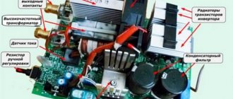
STMicroelectronics produces several series of IGBT transistors and high-power fast-acting diodes that are ideal for creating welding machine inverters. State-of-the-art IGBTs of the V, H, HB, M series and W series diodes are characterized by low switching losses and low saturation voltage. These remarkable qualities were confirmed in practice when testing MMA inverters with a power of 4 and 6 kW.
The welding equipment market is a fast-growing power electronics industry. Today there are many types of welding machines:
- with various technologies - manual arc welding with a consumable electrode (manual metal arc, MMA), manual welding in a shielding gas environment (tungsten inert gas, TIG), semi-automatic welding in an environment of inert gases (MIG) or active gases (metal active gas, MAG);
- with various current sources - transformer, inverter;
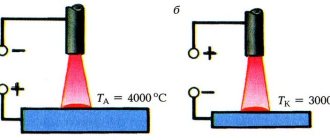
- with direct current output (for example, for welding steel) or with alternating current (for example, for welding aluminum).
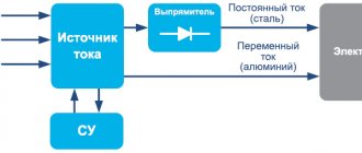
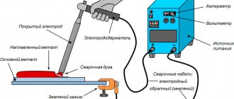
The most common type of welding technology is MMA. It is simple and is used in both professional and household devices. The structure of such a welding machine is quite simple and consists of a current source, an output rectifier (optional) and a control system (Figure 1).
Rice. 1. Simplified block diagram of the welding machine
The current source can be implemented on the basis of a powerful network transformer (transformer device), or on the basis of an inverter (inverter device). The main advantages of transformer devices are simplicity and maximum reliability, while the disadvantages are large dimensions, rough adjustment and poor welding quality. Inverter devices using modern semiconductor power switches do not have these disadvantages.
The main components of high-power inverters are IGBT transistors and high-speed diodes. The STMicroelectronics company produces power electronic components ideal for building welding machines [1]:
- V-series IGBTs with ultra-low turn-off energy, operating with voltages up to 600 V at frequencies up to 120 kHz;
- HB series IGBTs with low saturation voltage and low turn-off energy, operating with voltages up to 650 V at frequencies up to 50 kHz;
- H-Series IGBTs with low turn-off energy, operating with voltages up to 1200 V at frequencies up to 35 kHz;
- IGBT M series with low saturation voltage, operating with voltages up to 1200 V at frequencies up to 20 kHz;
- W series diodes with low forward voltage drop and minimal recovery time.
Requirements for IGBTs as part of welding inverters
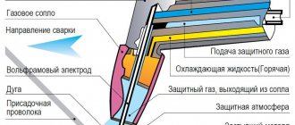
The operating principle of an inverter welding machine is quite simple (Figure 2). The mains supply voltage is rectified and supplied to the inverter input. The inverter converts DC voltage into AC voltage, which is transmitted to the load through a high-frequency power transformer. The operation of the inverter is controlled by a control system (CS). By increasing and decreasing the duration of control pulses, you can change the power transmitted to the load. In addition to the main blocks, the circuit also contains auxiliary ones: a power factor corrector (PFC) and an output rectifier.
Rice. 2. Structure of inverter welding machine
The main block of an inverter welding machine is the inverter itself, which can be implemented using any of the known topologies. Among the most commonly used circuits are push-pull, bridge, half-bridge, half-bridge asymmetrical (oblique half-bridge).
Despite the variety of topologies, the requirements for IGBTs are approximately the same:
- High operating voltage. For a household network, the transistor voltage rating should be 600 V or higher.
- Large switching currents. Average values reach tens of amperes, peak values reach hundreds of amperes.
- High switching frequency. Increasing the frequency allows you to reduce the dimensions of the transformer and the inductance of the output filter.
- Low energy value for switching on (Eon) and switching off (Eoff) to minimize switching losses.
- Low value of saturation voltage Uke us. to minimize conducted losses.
- Resistant to harsh switching conditions. The inverter operates with an inductive load.
- Short circuit resistance. Critical for bridge and half bridge circuits.
To the above, it is worth adding that, firstly, when choosing transistors for an inverter, you should pay attention not only to the ratings of currents and voltages, but also to the parameters that determine power losses. Secondly, the requirements for low saturation voltage and high operating frequency are contradictory.
IGBTs manufactured by STMicroelectronics combine unique characteristics: they are capable of switching high power, are characterized by high performance, while maintaining a low value of Uke us. This became possible thanks to the use of the latest technologies.
Bipolar device
IGBT is an insulated gate bipolar transistor used in inverter. In fact, it consists of two transistors on one substrate. The bipolar device forms a power channel, and the field one is a control channel.
The connection of two types of semiconductors allows you to combine the advantages of field and bipolar devices in one device. The combined device can, like a bipolar device, operate with high potentials; the channel conductivity is inversely proportional to the current, and not its square, as in a field-effect transistor.
In this case, the IGBT transistor has economical field device control. The power electrodes are called as in a bipolar device, and the control electrode is called a gate, as in a MOS device.
IGBT transistors for welding inverters and power drives, where they have to operate at high voltages, began to be used as soon as the technology for their production was debugged. They reduced the size, increased the performance and power of inverters. Sometimes they even replace thyristors.
In an IGBT inverter, to ensure the operation of powerful switches, drivers are used - microcircuits that amplify the control signal and accelerate fast charging of the gate.
Some models of IGBT transistors operate with voltages from 100 V to 10 kV and currents from 20 to 1200 A. Therefore, they are more often used in power electric drives and welding machines.
Field-effect transistors are more often used in pulsed sources and single-phase welding inverters. With current parameters of 400-500 V and 30-40 A, they have the best performance characteristics. But since IGBT devices can be used in more severe conditions, they are increasingly used in welding inverters.
Power losses and features of IGBT production technology from ST
The main reason for inverter power limitation is IGBT overheating. It is a consequence of power loss dissipated in the form of heat.
As is known, the total power loss in an IGBT (Pd) consists of two components: conduction losses (Pcond, conducted losses) and switching losses (Pswitch) (Table 1).
Table 1. Power losses in IGBT
| Parameter | IGBT |
| Total losses | Pd = Pcond + Pswitch |
| Conducted losses | Pcond = Uke us (rms) × Ik × D, where D is the duty cycle |
| Switching losses | Pswitch = Eswitch × f, where f is the switching frequency, Eswitch = (Eon + Eoff) - the total switching losses (given in the IGBT parameters) |
| Maximum power limited by chip overheating | Pd = (Tj – Tc)/Rth-jc, where Tc is the case temperature, Tj is the crystal temperature, Rth-jc is the “chip-to-case” thermal resistance (given in the IGBT parameters) |
Conducted losses are determined by the value of the saturation voltage Uke us. For this reason, they try to reduce it as much as possible.
Switching losses combine the energy spent on switching on (Eon) and switching off (Eoff).
The turn-on energy of Eukl is largely determined by the built-in antiparallel diode. To optimize this parameter, you can use an external diode with better characteristics (shorter recovery time) or optimize the switching mode (switching at zero currents or voltages).
The turn-off energy Evykl is determined by the efficiency of minority carrier recombination in the IGBT structure. Delaying the recombination process leads to the appearance of a current tail (Figure 3), [2].
Rice. 3. Turn-off loss for planar IGBT
During the on state, current flows through the IGBT and an accumulation of minority carriers (holes from the p+ layer) occurs in its n- layer. After turning off the transistor, the number of these accumulated carriers decreases quite slowly, mainly due to ineffective recombination in the low-doped n- layer. As a result, a current “tail” is formed, leading to additional power losses.
One way to improve performance is to reduce the doping level of the p+ region. This leads to a decrease in the number of carriers, and hence to an accelerated recombination process. However, a decrease in the number of carriers will obviously lead to an increase in the saturation voltage.
Rice. 4. Development of IGBT technologies produced by STMicroelectronics
Thus, increasing performance while maintaining saturation voltage is possible only through qualitative improvements and the use of new technologies. For example, to speed up the recombination process, an n+ layer is created between the p+ and n- layers (Figure 4a). Performance increases, but remains quite low.
One of the revolutionary solutions that made it possible to qualitatively improve the characteristics of IGBTs was the use of TGFS (Trench Gate Field Stop) technology (Figure 4b). The essence of TGFS is to change the structure of the gate, which is performed in an isolated groove. The conductive channel becomes vertical, which reduces the effective thickness of the n- layer. This, on the one hand, leads to a decrease in the saturation voltage, and on the other, to a decrease in the number of accumulated carriers.
The most modern generation of IGBTs produced by STMicroelectronics V series includes all the best technological solutions [2]: TGFS, reducing the thickness of the original p-wafer, reducing the thickness of the diffuse and epitaxial layers, increasing the gate penetration depth (Figure 4c). This allows you to reduce the energy spent on shutdown while maintaining the saturation voltage value.
STMicroelectronics produces several series of IGBTs with different characteristics. A wide selection allows you to find the optimal transistors, taking into account the requirements for a specific welding machine and the topology used.
Transistor - what is it and what are they?
In this article we will try to answer all these questions as fully as possible. We will describe their differences in more detail and which one is better to give your preference.
Every electronic design uses a transistor. It can be a children's toy or a ground-based aerial surveillance system. This miracle of technology is used in the production of computer equipment, audio and video equipment.
That is, resort to their help in building any microcircuit. The role of the transistor in the inverter is to amplify and control electric current. The invention of the transistor in 1948 provoked a powerful impetus in the evolution of science and technology.
Of course, this led to radical changes in the development of electronics.
The transistor plays a big role in the configuration of small-sized welding machines. An important advantage of them is the ability to work flawlessly at low voltage, as well as at high current.
It is used to generate, amplify, switch and convert electrical signals. A modern inverter weighs no more than 5 kg.
And this is thanks to the introduction of a compact circuit, which was assembled using transistors. This resulted in a reduction in the size of the entire welding machine.
A device with such dimensions greatly simplifies welding work in hard-to-reach places. If we compare the welding machine we are used to, which we used before, and the inverter, then we can say with confidence that the modern device is much easier to learn and use.
Of great importance is the number of additional functions that have been introduced into the device. It is this fact that allows a novice welder to start working without hesitation without risk.
A transistor is a semiconductor device, the main component of a modern welding inverter.
Due to the fact that the inverter is reliably installed in our everyday life, it will be useful to obtain maximum information about its electronic content.
This knowledge will be needed to understand the filling of the welding equipment that you use. Undoubtedly, the presence of many additional functions plays a big role. This allows the less welder to get to work without hesitation.
And since the inverter is reliably installed in our everyday life, it will be useful to get more information about its electronic content. This knowledge will be needed to understand the functions of the equipment you use.
Currently, there are two types of transistors that are used in welding inverters: IGBT and MOSFET. They played a role in reducing the dimensions, and also contributed to the expansion of additional capabilities of the device.
Review of IGBT series from ST
The IGBT line produced by STMicroelectronics contains four series, the representatives of which are most suitable for welding inverters. These are the V, HB, H, M series. All these transistors meet the above requirements and have excellent characteristics [1, 4]:
- high operating voltages – 600…1200 V;
- high switching currents – up to 80 A;
- record shutdown energy values – from 0.2 mJ;
- speed – up to 120 kHz;
- availability of versions with built-in high-speed antiparallel diode;
- availability of various housing versions (TO-247, D2PAK, TO-220 and others);
- resistance to short circuit impulses.
The M series is designed for switching voltages up to 1200 V and currents up to 40 A (Table 2). A distinctive feature of the series is its low saturation voltage (no more than 2.2 V) and low switching energy (from 1.2 mJ). This makes these transistors the optimal choice for inverters operating at frequencies up to 20 kHz.
Table 2. Characteristics of M-series IGBTs
| Name | Frame | Uke max., V | Ik max. at Tc = 100°C, A | Uke us. max., V | Eoff typ. at Tc = 125°C, mJ | Diode | Fmax, kHz | Pd max., W |
| STGW15M120DF3 | TO-247 | 1200 | 15 | 2,2 | 1,2 | There is | 20 | 283 |
| STGW25M120DF3 | TO-247 | 1200 | 25 | 2,2 | 2 | There is | 20 | 326 |
| STGW40M120DF3 | TO-247 | 1200 | 40 | 2,2 | 3 | There is | 20 | 468 |
| STGWA15M120DF3 | TO-247 LONG LEADS | 1200 | 15 | 2,2 | 1,2 | There is | 20 | 283 |
| STGWA25M120DF3 | TO-247 LONG LEADS | 1200 | 25 | 2,2 | 2 | There is | 20 | 326 |
| STGWA40M120DF3 | TO-247 LONG LEADS | 1200 | 40 | 2,2 | 3 | There is | 20 | 468 |
The H series is capable of switching voltages up to 1200 V and currents up to 40 A (Table 3). Compared to M-series transistors, H-series IGBTs have lower switching energy (from 0.85 mJ) and higher saturation voltage (up to 2.4 V). For this reason, they are suitable for higher frequency applications and are capable of operating at frequencies up to 100 kHz.
Table 3. H Series IGBT Specifications
| Name | Frame | Uke max., V | Ik max. at Tc = 100°C, A | Uke us. max., V | Eoff typ. at Tc = 125°C, mJ | Diode | Fmax, kHz | Pd max., W |
| STGW15H120DF2 | TO-247 | 1200 | 15 | 2,4 | 0,85 | There is | 50 | 260 |
| STGW15H120F2 | TO-247 | 1200 | 15 | 2,4 | 0,85 | No | 50 | 260 |
| STGWA15H120DF2 | TO-247 LONG LEADS | 1200 | 15 | 2,4 | 0,85 | There is | 50 | 260 |
| STGWA15H120F2 | TO-247 LONG LEADS | 1200 | 15 | 2,4 | 0,85 | No | 50 | 260 |
| STGW25H120DF2 | TO-247 | 1200 | 25 | 2,4 | 1,4 | There is | 50 | 375 |
| STGW25H120F2 | TO-247 | 1200 | 25 | 2,4 | 1,4 | No | 50 | 375 |
| STGW40H120DF2 | TO-247 | 1200 | 40 | 2,4 | 2,2 | There is | 100 | 468 |
| STGW40H120F2 | TO-247 | 1200 | 40 | 2,4 | 2,2 | No | 100 | 468 |
The HB series is not the main one for the construction of welding inverters, but its characteristics are also excellent (Table 4). The saturation voltage for these IGBTs is a record among all families and starts from 1.65 V. Switching energy, in many cases, does not exceed 0.6 mJ. The operating frequency for members of the family reaches 50 kHz.
Table 4. HB Series IGBT Specifications
| Name | Frame | Uke max., V | Ik max. at Tc = 100°C, A | Uke us max., V | Eoff typ. at Tc = 125°C, mJ | Diode | Fmax, kHz | Pd max., W |
| STGFW20H65FB | TO-3PF | 650 | 20 | 1,65 | 0,6 | No | 50 | 58 |
| STGFW30H65FB | TO-3PF | 650 | 30 | 1,65 | 0,6 | No | 50 | 58 |
| STGFW40H65FB | TO-3PF | 650 | 40 | 1,8 | 0,6 | No | 50 | 58 |
| STGW20H65FB | TO-247 | 650 | 20 | 1,65 | 0,6 | No | 50 | 260 |
| STGW30H65FB | TO-247 | 650 | 30 | 1,65 | 0,6 | No | 50 | 260 |
| STGW40H65DFB | TO-247 | 650 | 40 | 1,8 | 0,6 | There is | 50 | 283 |
| STGW40H65FB | TO-247 | 650 | 40 | 1,8 | 0,6 | No | 50 | 283 |
| STGW60H65DFB | TO-247 | 650 | 60 | 1,75 | 1 | There is | 50 | 375 |
| STGW60H65FB | TO-247 | 650 | 60 | 1,75 | 1 | No | 50 | 375 |
| STGW80H65DFB | TO-247 | 650 | 80 | 1,6 | 1,3 | There is | 50 | 469 |
| STGW80H65FB | TO-247 | 650 | 80 | 1,8 | 1,9 | No | 50 | 469 |
| STGWA80H65FB | TO-247 LONG LEADS | 650 | 80 | 1,8 | 1,9 | No | 50 | 469 |
| STGWT20H65FB | TO-3P | 650 | 20 | 1,65 | 0,6 | No | 50 | 260 |
| STGWT30H65FB | TO-3P | 650 | 30 | 1,65 | 0,6 | No | 50 | 260 |
| STGWT40H65DFB | TO-3P | 650 | 40 | 1,8 | 0,6 | There is | 50 | 283 |
| STGWT40H65FB | TO-3P | 650 | 40 | 1,8 | 0,6 | No | 50 | 283 |
| STGWT60H65DFB | TO-3P | 650 | 60 | 1,75 | 1 | There is | 50 | 375 |
| STGWT60H65FB | TO-3P | 650 | 60 | 1,75 | 1 | No | 50 | 375 |
| STGWT80H65DFB | TO-3P | 650 | 80 | 1,6 | 1,3 | There is | 50 | 469 |
| STGWT80H65FB | TO-3P | 650 | 80 | 1,8 | 1,9 | No | 50 | 469 |
Series V, as mentioned above, is the flagship in the STMicroelectronics range. Thanks to the latest technologies, these IGBTs have almost no current tail, and the turn-off energy is minimal - from 0.2 mJ (Table 5), while the saturation voltage does not exceed 2.15 V. All this allows the use of V series transistors in high-speed inverters with a maximum switching frequency of up to 120 kHz.
Table 5. V-Series IGBT Specifications
| Name | Frame | Uke max., V | Ik max. at Tc = 100°C, A | Uke us. max., V | Eoff typ. at Tc = 125°C, mJ | Diode | Fmax, kHz | Pd max., W |
| STGB20V60DF | D2PAK | 600 | 20 | 2,15 | 0,2 | There is | 120 | 167 |
| STGB20V60F | D2PAK | 600 | 20 | 2,15 | 0,2 | No | 120 | 167 |
| STGFW20V60DF | TO-3PF | 600 | 20 | 1,8 | 0,2 | There is | 120 | 52 |
| STGFW20V60F | TO-3PF | 600 | 20 | 2,15 | 0,2 | No | 120 | 167 |
| STGP20V60DF | TO-220AB | 600 | 20 | 2,15 | 0,2 | There is | 120 | 167 |
| STGP20V60F | TO-220AB | 600 | 20 | 2,15 | 0,2 | No | 120 | 167 |
| STGW20V60DF | TO-247 | 600 | 20 | 2,15 | 0,2 | There is | 120 | 167 |
| STGW20V60F | TO-247 | 600 | 20 | 2,15 | 0,2 | No | 120 | 167 |
| STGWT20V60DF | TO-3P | 600 | 20 | 2,15 | 0,2 | There is | 120 | 167 |
| STGWT20V60F | TO-3P | 600 | 20 | 2,15 | 0,2 | No | 120 | 167 |
| STGB30V60DF | D2PAK | 600 | 30 | 2,15 | 0,3 | There is | 120 | 260 |
| STGB30V60F | D2PAK | 600 | 30 | 2,15 | 0,3 | No | 120 | 260 |
| STGFW30V60DF | TO-3PF | 600 | 30 | 2,15 | 0,3 | There is | 120 | 58 |
| STGFW30V60F | TO-3PF | 600 | 30 | 2,15 | 0,3 | No | 120 | 58 |
| STGP30V60DF | TO-220AB | 600 | 30 | 2,15 | 0,3 | There is | 120 | 260 |
| STGP30V60F | TO-220AB | 600 | 30 | 2,15 | 0,3 | No | 120 | 260 |
| STGW30V60DF | TO-247 | 600 | 30 | 2,15 | 0,3 | There is | 120 | 260 |
| STGW30V60F | TO-247 | 600 | 30 | 2,15 | 0,3 | No | 120 | 260 |
| STGWT30V60DF | TO-3P | 600 | 30 | 2,15 | 0,3 | There is | 120 | 260 |
| STGWT30V60F | TO-3P | 600 | 30 | 2,15 | 0,3 | No | 120 | 260 |
| STGB40V60F | D2PAK | 600 | 40 | 2,15 | 0,5 | No | 120 | 283 |
| STGFW40V60DF | TO-3PF | 600 | 40 | 2,15 | 0,5 | There is | 120 | 62,5 |
| STGFW40V60F | TO-3PF | 600 | 40 | 2,15 | 0,45 | No | 120 | 60 |
| STGP40V60F | TO-220AB | 600 | 40 | 2,15 | 0,5 | No | 120 | 283 |
| STGW40V60DF | TO-247 | 600 | 40 | 2,15 | 0,5 | There is | 120 | 283 |
| STGW40V60F | TO-247 | 600 | 40 | 2,15 | 0,5 | No | 120 | 283 |
| STGWT40V60DF | TO-3P | 600 | 40 | 2,15 | 0,5 | There is | 120 | 283 |
| STGW60V60DF | TO-247 | 600 | 60 | 2,15 | 0,75 | There is | 120 | 375 |
| STGW60V60F | TO-247 | 600 | 60 | 2,15 | 0,75 | No | 120 | 375 |
| STGWT60V60DF | TO-3P | 600 | 60 | 2,15 | 0,75 | There is | 120 | 375 |
| STGFW80V60F | TO-3PF | 600 | 80 | 2,15 | 1,15 | No | 120 | 79 |
| STGW80V60DF | TO-247 | 600 | 80 | 2,15 | 1,15 | There is | 120 | 469 |
| STGW80V60F | TO-247 | 600 | 80 | 2,15 | 1,15 | No | 120 | 469 |
| STGWT80V60DF | TO-3P | 600 | 80 | 2,15 | 1,15 | There is | 120 | 469 |
| STGWT80V60F | TO-3P | 600 | 80 | 2,15 | 1,15 | No | 120 | 469 |
To name the IGBTs of the presented series, a code consisting of eight positions is used (Table 6). It contains the component type, package designation, family name, breakdown voltage, diode presence and its characteristics. It is worth noting that versions of transistors with a low voltage drop diode (DL index) are not suitable for use in welding inverters.
Table 6. Naming of IGBT manufactured by STMicroelectronics
| STG | W | 60 | V | 60 | D | F | 3 |
| Generation technology | |||||||
| Trench gate Field Stop technology | |||||||
Built-in diode:
| |||||||
Breakdown voltage code:
| |||||||
Series:
| |||||||
| Maximum current at 100°C | |||||||
| Frame: | |||||||
| F – TO-220FP | WA – TO-247 Long Led | ||||||
| FW –TO3FP | WT – TO-3P | ||||||
| P – TO-220 | Y – Max247 | ||||||
Most of the IGBT families presented are available in two versions: with a built-in high-speed diode and without it. The characteristics of these diodes are quite good. However, if necessary, it is necessary to use external diodes, for example, in an asymmetric bridge circuit. In this case, you should pay attention to the powerful high-speed diodes of the W series produced by STMicroelectronics.
IGBT bipolar transistor
I suggest you pay attention to the bipolar transistor with an insulated gate - this is an IGBT. In fact, these are two transistors on one substrate. IGBT allows you to get high output current with minimal heating.
It is capable of amplifying and generating electrical vibrations. IGBT models began to be used in welding inverters, where there was a need to operate at the highest voltages.
As a result, it became clear that the production of welding machines can be brought to a higher level exclusively with the help of IGBTs.
Very often, for uninterrupted operation of powerful switches, special microcircuits are implanted into the IGBT transistor.
Review of powerful W series diodes from ST
Powerful high-speed diodes of the W series are designed specifically for operation as part of high-power pulse converters with harsh switching conditions. For this purpose, their characteristics are optimized accordingly (Table 7):
- to reduce static power, the forward voltage drop is reduced (from 0.92 V);
- reverse voltage reaches 600 V;
- average current reaches 200 A;
- recovery time and reverse current are significantly reduced to reduce switching energy;
- Most diodes are available in dual versions.
Table 7. Powerful high-speed diodes produced by STMicroelectronics
| Name | Frame | Diodes in the housing | Urev max., V | Iav max., A | Udirect max. at current, V | trestore max., ns | Tcrystal max., °C |
| STTH20W02C | TO-247 | 2 | 200 | 10 | 1.05 (10 A) | 25 | 175 |
| STTH30W02C | TO-247 | 2 | 200 | 15 | 1.15 (15 A) | 27 | 175 |
| STTH60W02C | TO-247 | 2 | 200 | 60 | 0.92 (30 A) | 30 | 175 |
| STTH200W03TV1 | ISOTOP | 2 | 300 | 200 | 1.15 (100 A) | 50 | 150 |
| STTH60W03C | TO-247 | 2 | 300 | 30 | 1.15 (30 A) | 35 | 175 |
| STTH30W03C | TO-247 | 2 | 300 | 15 | 1.4 (15 A) | 25 | 175 |
| STTH200W04TV1 | ISOTOP | 2 | 400 | 200 | 1.55 (100 A) | 55 | 150 |
| STTH61W04S | TO-247 | 1 | 400 | 60 | 1.15 (30 A) | 55 | 175 |
| STTH100W04C | TO-247 | 2 | 400 | 100 | 1.2 (50 A) | 50 | 175 |
| STTH200W06TV1 | ISOTOP | 2 | 600 | 200 | 1.3 (100 A) | 75 | 150 |
| STTH100W06C | TO-247 | 2 | 600 | 100 | 1.15 (50 A) | 75 | 175 |
| STTH50W06S | TO-247 | 1 | 600 | 50 | 1.75 (50 A) | 45 | 175 |
Results of practical application of IGBT from ST in MMA inverters
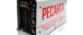
To confirm the advantages of IGBT transistors manufactured by STMicroelectronics, welding inverters were built and tested: MMA160 (input power 3.8 kW) and MMA200 (input power 6 kW) [3].
The test conditions were the same [3]:
- in both cases, an asymmetrical half-bridge inverter circuit with paired parallel IGBTs was used (Figures 5 and 6);
- mains voltage 220 V, 50 Hz was used as power supply;
- The ambient temperature was 25°C;
- Ceramic resistors with a total resistance of 145 mOhm with active cooling were used as a load;
- the maximum fill factor did not exceed 50% to ensure that there is no possibility of saturation of the output RF transformer core;
- protective shutdown was carried out when the transistors reached a temperature of 105°C.
The MMA160 inverter was built on the basis of STGW40V60DF transistors (Figure 5). The switching frequency was 63 kHz.
Rice. 5. MMA160 inverter circuit
During the tests, measurements were taken of input power, input current and transistor housing temperature. When the input power increased from 2 kW to a maximum power of 3.8 kW, the transistors warmed up and the turn-off energy increased (Table 8).
Table 8. Test results of the MMA 160 inverter
| Input power, kW | Input current, A | Power factor | Temperature, °C | Time | Switch-off energy, mJ |
| 2 | 15,4 | 0,58 | 62 | – | 311 |
| 3 | 22,2 | 0,61 | 83 | – | 466 |
| ~3.8 (max) | 26,3 | 0,66 | 105 | 10 min 17 sec | 550 |
The inverter showed stable operation over the entire power range. The shutdown at maximum power occurred only after 10 minutes 17 seconds, after the overheating protection (105°C) was activated. The maximum energy value for turning off the IGBT increased from 311 mJ to 550 mJ, which is a good result and corresponds to the value stated in the documentation (Table 5).
The MMA200 inverter was built using twin STGW60H65DFB IGBTs (Figure 6). The operating frequency was 63 kHz. For additional protection of transistors, snubber RC circuits were used.
Rice. 6. MMA200 inverter circuit
During testing, the MMA200's input power was increased from 2.6 kW to 5.8 kW. The inverter demonstrated stable operation in all modes and turned off after the temperature protection was activated 8 minutes 15 seconds after reaching a power of 5.8 kW. As the input currents increased, the transistor temperature increased and the turn-off energy increased (Table 9). The range of energy changes during shutdown was 586...947 mJ, which corresponds to the declared value.
Table 9. MMA200 inverter test results
| Input power, W | Output current, A | Output power, W | Temperature, °C | Time | Switch-off energy, mJ |
| ~2683 | 90 | ~2233 | 59 | – | 586 |
| ~3864 | 130 | ~3172 | 71 | – | 787 |
| ~4949 | 165 | ~3997 | 87 | – | 887 |
| ~5883 | 200 | ~4624 | 105 | 8 min 15 sec | 947 |
The tests carried out confirmed the excellent characteristics declared by the manufacturer. Thus, IGBTs manufactured by STMicroelectronics are ideal for building inverters for welding machines.
Literature
- Products and solutions for Factory automation and control. STMicroelectronics, 2015;
- Giuseppe Introvaia. TA0350. Technical article. New trench gate field-stop V series: the real tail-less IGBT. Rev. 1. STMicroelectronics, 2013;
- Anselmo Liberti, Rosario Gulino. AN4638. Application note. Welding machines: V and HB series IGBTs on two-switch forward converters. Rev. 1. STMicroelectronics, 2015;
- https://www.st.com/.
Obtaining technical information, ordering samples, ordering and delivery.
•••