There are many characteristics of electric current. One of the most important is electrical resistance. It characterizes the ability of a current conductor to prevent the free and unhindered passage of the latter. Resistance is denoted by the letter R of the Latin alphabet and is measured in Ohms.
The importance of this value can hardly be overestimated, therefore any modern multifunctional devices contain a resistance measurement function. This article will discuss in detail what the resistance of an insulation wire is, how to determine the resistance of a resistor with a multimeter, and how resistance is measured in general.
Ohm's law in the table makes it clear how the three main parameters of the electrical network depend on each other
Types of electrical measuring instruments
Classification of electrical measuring instruments:
- variable;
- permanent;
- combined devices.
By level of accuracy:
- 0, 05;
- 0,1;
- 0,2;
- 0,5;
- 1,0.
Each number indicates a percentage of the permissible error.
According to the essence of the work:
- electromagnetic;
- induction;
- magnetoelectric;
- ferromagnetic.
When carrying out measurement tests, it is necessary to select the appropriate measuring device correctly.
- Ammeters are devices for measuring current values. The unit of measurement is Ampere (A).
- Voltmeter – measures the voltage of the electrical network. The unit of measurement is Volt (V).
- An ohmmeter is an auxiliary device that measures resistance in an electrical circuit. Measured in Ohms (Ohm).
- A wattmeter is an element that measures network power. The unit measured is Watt (W).
- Frequency meter – a frequency meter for alternating pulse values. Measured in Hertz (Hz).
What is wire insulation resistance
Insulation resistance is one of the most important parameters of any cables and conductors. This is based on the fact that all wires are subject to external influences during their operation. In addition to external influence, there are also internal ones: the influence of the cores of one wire on each other, interaction through electromagnetic fields. All this, one way or another, leads to leaks.
Industrial megger for measuring large resistance values
That is why any electrical and non-electrical wires are created with insulation that protects the conductor from external influences. Popular insulating materials include rubber, polyvinyl chloride, oil, wood and paper. These materials are used based on the purpose of the cable. For example, wires buried underground are insulated with relatively thick dielectric tape, while telecommunications cables may be enclosed in a simple aluminum foil wrapper.
Old Soviet analog bench ohmmeter
Important! Insulation is the protection of cores from exposure to otherworldly factors, protection of cores from each other, from short circuits and from various leaks. Insulation resistance is the amount of resistance between the conductors of a wire or between one of the conductors and the insulating layer.
Any material ages and deteriorates over time, which leads to deterioration of its characteristics and a decrease in insulation resistance to direct or alternating current. The insulation resistance characteristic is indicated on the cable and is standardized in its GOST. It is determined in laboratory conditions at a temperature of 20 degrees.
Carrying out resistance measurements with a professional megohmmeter
Low-frequency communication cables have a minimum insulation resistance of 5 Gigaohms per kilometer, and coaxial cables, in turn, have a minimum insulation resistance of 10 Gigaohms per kilometer. Measurement and testing of resistance is carried out on a regular basis with a megohmmeter: at mobile communication installations - once every 6 months, at high-risk facilities - once every 12 months, at other facilities - once every three years.
You may be interested in Voltage measurement
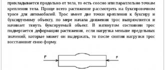
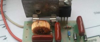
Resistor to increase the resistance of the electrical network
Device, principle of operation
Let's look at the operation of electrical devices using the example of basic devices, such as:
- ammeters;
- voltmeters;
- ohmmeters.
Ammeters
Such devices measure the amount of electric current. Since the readings directly depend on the incoming electrical signal, the ammeter resistance should be less than the load resistance. This is necessary for a constant charge force when connecting a load. According to their design features, such electrical measuring instruments are divided into:
- AC ammeter;
- DC ammeter;
- magnetoelectric;
- electromagnetic.
How does an ammeter work? An ideal ammeter is a device for measuring electric charge. It is a conductive circuit mounted on an axis between the poles of a permanent magnet.
In the absence of a circuit signal, due to spring pressure, the arrow is in the zero position. When the device is turned on, a current pulse is sent to the moving element - the needle deflects by an angle corresponding to the current value. Thus the indicator scale shows the value measured by the device.
There are modifications: with an analogue scale, with a digital scale. In addition, devices differ in division price and measurement limits.
Analog AC voltmeter and digital voltmeters.
- permanent;
- variable.
An ideal electrical voltmeter is usually connected to the circuit in parallel. The resistance of a voltmeter is proportional to the signal applied to it. In order to prevent the readings from being affected by distortions of electrical pulses, it is recommended to make its resistivity as large as possible.
There are also digital voltmeters that have digital readouts. The principle of operation of a voltage meter is similar to a current meter, the only difference is in the scale graduations, measurement limits and modifications.
Ohmmeter
A device that allows you to measure both the resistance of an ammeter and the resistance of a voltmeter. Measurement range:
- units, tens (Ohm);
- hundreds, thousands (Ohm).
Such an indicating element is connected to the circuit in series.
Measures indirectly the value of resistance, taking into account the value of the incoming electric current and a constant voltage value. The instrument scale of each electrical device has symbols printed on it, indicating the characteristics of the device, accuracy class (for example, an ammeter), types of operating currents, rated voltage, etc.
An example of a modern resistance meter is the Vitok ohmmeter, which has a combined power supply.
Classification of multimeters
Multimeters used to measure resistance can be analog or digital in design. For analog instruments, the value of the measured resistance value can be determined by the graduated scale of the device, on which the arrow of the device stopped during the measurement. For digital instruments, the measured value is displayed as a digital value on its own display.
Analog devices
Analog multimeters have another name - pointer meters . Experienced users and professional electricians continue to work with them. They appeared several decades ago, much earlier than digital devices. They are based on a dial microammeter with a set of additional resistors and shunts of a high accuracy class.
Resistance is measured with a multimeter by installing the switch located on its front panel at various points in the “Ω” sector. Depending on the value of the measured resistance, the switch positions determine the boundaries of the range in which the result is expected. These can be marks: Ohm (Ω), kOhm (1k), tens of kOhms (x10), hundreds of kOhms (x100).
Resistance values greater than 1 MOhm are usually not measured with an analog multimeter. This is due to the nonlinearity of the instrument scale. It has the greatest accuracy on the right side (approximately the first 2/3). Then its digitization is compressed. Accordingly, it is better not to use the left side of the scale and switch to another measurement limit.
The voltage of the battery involved in measuring the resistance value is limited by its nominal value, therefore, when measuring a large resistance, the current flowing through it is very small. The instrument needle barely deviates to the left side of the scale, where the measurement error has its maximum value. In any case, the measurement accuracy does not exceed 2%.
Before measuring resistance, the ends of the probes of the device must be connected to each other and by rotating the variable resistor handle located on the front panel, set the arrow position corresponding to the zero mark of the resistance measurement scale. If it is not possible to set the arrow to “0”, then a decision is made to replace the battery.
Digital devices
Digital multimeters today are used by most people who need to measure resistance. The result of the measurement is displayed on the indicator board with numbers that correspond to the value of the measured resistance. To do this, the biscuit switch on the front panel of the device must be moved to one of the positions of the “Ω” sector. Depending on the value of the resistance being measured, the choice of this position should be such that the measurement limit is higher than the resistance value to be measured.
The latest models of multimeters have 5 measurement limits, which start at 200 (up to 200 Ohms) and go up to 2000k (2,000,000 Ohms).
The multimeter's test leads must be connected to the extreme points of the part (resistor). If the nominal resistance of the resistor is greater than the measurement limit of the selected range, then “1” will be displayed on the digital indicator of the device. After this, it is necessary to change the measurement limit upward. If the range is selected correctly, the numbers on the indicator will show the value of the resistor resistance. The number “1” on any of the selected ranges indicates a faulty resistor or, as happens quite often, a lack of contact between the probes of the device and the resistor.
There are also frequent cases of breaks in the wires of the measuring probes. To check their serviceability, it is necessary to reliably connect their ends to each other, having previously set the lowest measurement limit with a switch. In this case, the numbers on the indicator should show a value close to zero. After such a check, a decision should be made: the resistor being tested or the measuring probes are faulty. In the latter case, it is necessary to carry out their thorough repair. The proper condition of the measuring part will save a lot of time in the future.
By the way, the same trouble can happen when working with an analog multimeter.
Comparison of different types of multimeters
Digital multimeters are easier to work with than analog ones. Many novice users believe that using an analog multimeter requires special training and extensive practical experience in working with them. This is true.
The arrow readings must also be correctly interpreted depending on the selected scale (“Ω “) and the position of the biscuit switch multiplier. The accuracy of analog multimeters is also poor. It depends on the accuracy class of the microammeter used in them. The accuracy class is indicated on the instrument scale.
On the other hand, the readings of analog multimeters are more stable. The information from the instrument pointer is averaged and does not change with instantaneous fluctuations in the measured value. This property is inherent in the magnetoelectric system of the microammeter. The readings of the digital multimeter in this situation will change chaotically. And the reason for such sharp fluctuations can be a banal alternating contact of the measuring probes with the part being tested.
Analog multimeters are less susceptible to various electromagnetic radiation. The circuits of digital devices contain a certain number of semiconductor elements, and they are very susceptible to such external influences.
Both types of multimeters use a battery. In digital devices, the circuit provides for the presence of a power source discharge sensor. At his command, the device turns off, signaling this. In the same situation, the analog multimeter continues to work with incorrect readings.
Many digital multimeters have a “beep” function with an audible alarm. It is very comfortable. If the resistance of the circuit being measured is less than 50 ohms, a tone will sound to attract attention. The most “advanced” models are equipped with a function for storing the measured value (the “HOLD” button on the front panel of the device). It is convenient to work with such samples in hard-to-reach places. But the button must be pressed not before, but during the measurement. Otherwise, the readings will be unreliable.
How to connect
Electrical measuring instruments are connected:
The ammeter is connected in series, next to the resistor, near which the current value will be measured.
How to use an ammeter? This diagram is simple enough to understand how to use an ammeter correctly.
Figure 5 shows:
- R – resistor;
- A – current measuring element;
- I – direction of electric charge.
How to use a voltmeter? The electrical appliance has parallel connections in those places where the voltage will be measured.
Figure 6 shows:
- R – resistance element;
- V – voltage meter.
How to use an Avometer? This type (voltmeter-ampmeter) is a combined device. In the case of measuring a current signal, it is connected as an electric charge meter. If voltage is measured - like a voltage meter.
A digital voltmeter-ampmeter is considered more convenient to use. When using electrical appliances, it is necessary to comply with all fire safety rules and for proper operation, take into account all their design characteristics.
Comments:
Alexei
An explanatory article, everything is described in detail. By the way, I have exactly the same multimeter as in the picture. I'm just starting to use it, so the step-by-step instructions were very helpful
Slavon
How do I know what sensitivity should be set initially? Do I have to know the resistance in order to measure it?
Yaroslav
Slavon, look at the nominal value of the element being measured and set the sensitivity based on it, if this is not possible or you want to measure the total resistance of several parts or the board as a whole - set the maximum first, measure - if you don’t get the result - change it to a lower level, then again and again . Eventually you will get your values.
Virtual Private Servers
Therefore, you should replace a discharged battery with a new one if you want the multimeter to show the correct values of the measured parameters.
Leave a comment Cancel reply
Related Posts
How to choose clamp meters and not overpay
The Fluke professional multimeter is a model of quality, a “Mercedes” in the field of measuring instruments
Is it worth buying a NEU-M electrician's kit or is it better to do the math first?
Review of bags for electricians, what you should pay attention to
Measurement of current, voltage, resistance
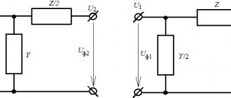
Voltage measurement Voltmeters are used to measure voltage. Voltmeters are connected in parallel to the section of the circuit where the voltage needs to be measured. To ensure that the device does not consume high current and does not affect the voltage of the circuit, its winding must have a high resistance. The greater the internal resistance of the voltmeter, the more accurately it will measure the voltage. For this purpose, the voltmeter winding is made of a large number of turns of thin wire. To expand the measurement limits of voltmeters, additional resistances are used, connected in series with the voltmeters. In this case, the network voltage is distributed between the voltmeter and the additional resistance. The value of the additional resistance must be selected in such a way that in the circuit with increased voltage the same current passes through the voltmeter winding as at the rated voltage. The current for which the device winding is designed is Iv =U/rv. In a circuit with a voltage n times greater, the current of the voltmeter with additional resistance r should remain the same: I in =nU/(r in + r) or U/r in =nU/(r in + r), hence the value of the additional resistance is equal to r = r in (n-1). Additional resistances are made from manganin wire wound on a getinax or porcelain frame and placed inside the device or separately from it. To measure high AC voltages, voltage measuring transformers are used.
Power factor measurement The power factor value in single-phase alternating current networks can be determined from the readings of a voltmeter, ammeter and wattmeter according to the formula cos φ=P/UI. Using the same devices, the power factor in three-phase current networks with a uniform load can be determined by the formula cos φ=P/UI√3, where U and I are linear voltage and current, and φ is the shift angle between phase voltage and current. The average value of the power factor cos φ avg for a certain period of time can be determined from the readings of active and reactive energy meters for the same time according to the formula cos φ avg = A a /√(A a 2 + A p 2 ), where A a is active energy ; And p is reactive energy. In practice, the instantaneous value of the power factor is determined using special devices - phase meters.
Measuring the smoothness of the potentiometer
For the next test we will need not probes, but crocodiles. Or help from a friend. We remember that you cannot touch the conclusions - the result will be compromised. We attach one crocodile to the middle contact of the potentiometer, the other to any extreme one. And turn the regulator. The numbers on the multimeter screen should change each other smoothly. The slightest rotation should lead to changes in value. A dial multimeter is more accurate in this regard - if the needle trembles or jumps when rotating, then the resistor is in the firebox. Although they say it can be repaired. We watch the video - in it the specialist clearly shows how to assess the possibility of repair and carry it out.
How to measure resistance with a multimeter
Multimeters are widely used not only by professional electricians, but also by home craftsmen. Using them, it is possible to measure all known electrical quantities used in practice in various electrical networks. In this article we will look at how to measure resistance with a multimeter. For such purposes, there is a built-in ohmmeter, which makes it possible to check this parameter and obtain a certain value for transformers, coils, capacitors, various electronic elements, as well as cables and wires.
Measurement Safety Precautions
Even when there is a need to measure the insulation resistance of a wire in domestic conditions, before using a megohmmeter you need to familiarize yourself with the safety requirements. Main rules:
- Hold the probes only in an isolated area limited by stops.
- Before connecting the product, the voltage is turned off, you need to make sure that there are no people nearby (along the entire measured area, when it comes to wires).
- Before connecting the probes, the residual voltage is removed by connecting a portable ground. It turns off when the probes are installed.
- After each measurement, the residual voltage is removed from the probes and the bare areas are connected.
- Upon completion of the measurements, a portable grounding is connected to the core and the residual charge is removed.
- Work is carried out with gloves.
Using a multimeter in practice
We measure alternating voltage
Let's measure the voltage in the outlet. To do this, move the switch to the alternating voltage measurement scale and set it to 600 Volts.
Next, carefully insert the probes into the socket and watch the readings. There is no special sequence for this action, you can insert the red probe on the left and the black one on the right and vice versa.
You may ask, why 600 Volts if the outlet only has 220 Volts? This is done for measurement accuracy, for example, we assume that there is 220 Volts in the outlet, but in fact, your management company or the energy company that supplies electricity to your home cannot cope and cannot give you a stable 220 Volts.
When measured at 600 volts, the display will show a value less than 200 volts. If this happens, then you should turn the switch to 200 Volts and then the device will show more accurate data.
As you can see from the photo below, my electricity suppliers do an excellent job.
Measuring DC voltage
Let's measure the voltage the battery produces. To do this, set the switch to this position (see figure below):
Next, connect the red wire to the positive of the battery, and the black wire to the negative and take readings. You can use the HOLD button to record the result.
The resulting value is 0.12 - this tells us that the battery voltage is less than what we set on the multimeter scale. Without hesitation, we move the switch to a lower value and get correct and clear readings.
Continuity for short circuit
Let's determine the integrity of the extension cord.
We put the switch in the dialing position, like this:
We touch the red probe to one of the contacts of the plug, and plug the black probe into the socket of the extension cord.
If a beep is heard, this tells us that the extension cord, starting from the plug contact to the socket connector, is intact.
Next, in the same way we check the second contact of the plug and the opening of the socket.
Let's say you checked one core and a sound signal was heard, but when checking the second core, there was no sound signal. This means that there is a break in the second core and such an extension cord will not work.
Preparing for measurements
The accuracy of the results largely depends on the correct settings of the measuring device. The multimeter is controlled by a rotary-type round knob. A scale is marked around it, consisting of several sectors separated by lines or different colors.
The device is switched to resistance measurement mode by turning the knob and moving it to the position opposite the “Ω” icon. Specific operating modes in different devices are set differently:
- Icons Ω, kΩ – x1, x10, x100, MΩ. They are located on the scale of any analog tester. The readings marked with an arrow are converted to a more modern format. When applying, for example, 1-10 on a graduation scale, for each mode you will need to multiply the result obtained by this coefficient.
- Symbols 200, 2000, 20k, 200k, 2000k. They are marked on the scale of an electronic device (multimeter) and indicate a certain range in which it is possible to measure resistance. The letter k indicates the prefix “kilo”, equivalent to 1000, determined for calculations by a unified measuring system. For example, if the multimeter is set to the “200k” position, and the number 178 is displayed on the display, then the resistance will be 178 x 1000 = 178,000 Ohms, and the maximum permissible for measurements is 200,000 Ohms.
- The “Ω” icon on the body indicates the possibility of automatic range detection. On the dials of such devices there are not only digital, but also letter designations - 15 kOhm, 2 Mohm, etc.
Calculation and verification
If you have data on the current strength and the electrical potential difference, that is, the voltage in the conductor, you can calculate the resistance using the formula:
Here U is voltage, V; I – current strength, A.
To verify the correctness of the calculation or to find out the resistance of elements that is unknown in advance, special measuring instruments are used. If it is necessary to measure only the resistance, an ohmmeter is used, but in everyday life they often use a universal device - a multimeter.