Welding methods
The classification of welding methods is regulated by GOST 19521 and provides for three main methods based on energy:
- Thermal.
- Thermomechanical.
- Mechanical.
The thermal method includes types of welding that involve joining parts by melting, which also involves the use of thermal types of energy, such as arc and gas. The thermomechanical method includes types of welding in which thermal energy is used in combination with pressure: electric contact, diffusion, gas press.
The mechanical method involves types of welding that are carried out using pressure and mechanical forces: cold welding, ultrasonic, explosion and friction welding. Cold welding is divided into spot, seam, and butt welding.
The degree of mechanization distinguishes between manual, semi-automatic, and automatic methods of the welding process. Each welding method has its own characteristics, so a special technological document is drawn up for a certain type of work.
What is a technological map
A welding flow chart is a design document, essentially a detailed step-by-step instruction manual for a welder tasked with joining metal parts using this method.
The welding map is drawn up by the process engineer, signed by him and subject to approval by the chief engineer.
The welder is issued a welding flow chart for the correct implementation of the work ahead of him. The technological map of welding works is a kind of collection of instructions on how, in what order and with the help of what equipment it is necessary to connect metal parts to each other and how to control the quality of the resulting connection.
There are many types of joining metal parts by welding. Each specific case has its own characteristics. Therefore, even the most experienced welder must understand the nuances of the work ahead of him before starting work. A technical map for welding metal structures, which is an integral document included in the general set of all necessary equipment, can provide invaluable assistance in this regard.
Only those welders who have passed certification can be allowed to work, having proven, among other things, the ability to competently understand technological maps and use them. The presence of this document is a kind of prevention of injuries and burns to the welder, since it describes in detail the safety rules that must be followed when carrying out such a complex process as welding.
A technological map for welding metal structures is drawn up and used when carrying out work at a professional level. The form and rules according to which the technological map for welding metal structures is filled out are regulated by GOST 3.1705-81.
Where is the technological map used?
The technical process map is a component of all welding work at a professional level. The standard should be used as a guide in every organization: in large industries, in welding shops, in small factories, construction sites. If several operations are required, a set of cards is developed for all welded joints. The documentation is kept by the chief engineer.
An operational technical map is required for laying gas pipelines and pipelines, when performing installation work, assembling vehicle parts, welding pipes, lattice metal structures and in many other areas.
We recommend that you read
Why do you need a welding log?
Why do you need a technical map?
The welding process consists of many steps, which are not easy to remember even for an experienced welder. In addition, although there are general recommendations, each connection of metal parts made using the welding process has its own nuances.
A technological map for welding work provides significant assistance. Before starting the process, the welder must familiarize himself with the welding data sheet. The presence of this document is of particular importance during critical welding work. These types include, for example, a technological map for welding pipelines.
It is also of great importance to have such guidance material as a technological map of assembly and welding work when performing complex installation work of large structures and similar tasks.
At the same time, the welder will have a complete picture of the work ahead of him, the stages and transitions between them. He will have an idea of how to control the resulting welded joint and what equipment needs to be prepared for this. Having a welding process map will improve the quality of the work performed and get a good result.
In addition to the welder, the welding technical map can be used by workers whose responsibilities include monitoring the resulting welded joints.
The presence of a technical map for welding work allows you to increase the productivity and efficiency of the welder when assembling various metal parts in this way, so its importance cannot be overestimated.
What data is indicated on the card?
The technological map describes in detail the technical process for welding metal structures.
The information indicated in the technological map includes:
- Information about the main materials that make up the parts being welded.
- Type of welding.
- Equipment used.
- Parameters that should be set on the equipment used.
- Temperature regime.
- Ways to prepare for the process.
- Fixation of products.
- The sequence in which the weld should be formed.
- Standards used.
- Safety regulations.
- Methods for monitoring the resulting connection.
In addition to the listed items, any additional items may be added to the welding chart at the discretion of the process engineer or customer.
When drawing up a contract, customers can put forward their requirements, for example, regarding the timing of the process or monitoring of the resulting connections.
The description of the material of the parts being welded is one of the most important points of the technological map for welding work on metal structures. It must contain information about the grade of metal of the parts being welded, their parameters and characteristics, the steel group, and information about how the edges of the parts should be cut.
The development of a technological map begins with an analysis of the parts to be welded and the selection of a welding method depending on the conditions under which it will be performed. According to calculations and instructions from regulatory materials, the welding mode, number of passes and other characteristics are selected.
Each card is assigned its own identification number. It is indicated in the technical documentation, as well as specifications. All technological maps are stored in the department of the chief technologist. They are given to the welder before starting work. Failure to comply with the recommendations specified in the card may result in a poor-quality connection of products, which can lead to destruction of the structure.
Welding process map
Welding is a complex process, the implementation of which must be carried out in a strict sequence of certain actions that are associated with the preparation of the metal, the execution of the welded joint and subsequent control. The weld, if not given proper attention, is a weak point in any welded structure. The reason for this may be shortcomings in the development of welding technology or its absence at all, insufficient control, and poor choice of welding equipment and materials. The result is a large number of defects and losses incurred by the organization to eliminate them. Losses can be prevented by correctly developing instructions for performing welding work and monitoring its implementation.
So what is a welding flow chart? A welding process map, or as it is also called a welding process map, is a document that is the result of the development of a welding technology for a specific joint, which specifies the most important technological parameters for creating a welded joint; in fact, it is an instruction for welding joints. The welding technological map was approved and put into active use on January 1, 1984, more than 30 years ago. When developing a technology for welding metal structures, each welded joint must be made in accordance with the welding flow chart developed for it.
The welding process sheet must contain the following data:
1. Information about the base metal.
2. Information on the quality and preparation of the joint for welding: data on the cutting (gap size, bluntness size, angle of inclination of the cutting, etc.), on the number and location of tacks, data on preliminary cleaning of the edges, dimensions of the seam.
3. Data on fixation of the welded product and possible heating. As well as the sequence of passes in the weld.
4. Information about the welding equipment and welding materials used. The selection of welding materials and equipment is based on various information obtained from literature, including professional welding literature (magazines, articles), personal experience, as well as feedback from organizations.
5. Information about the welding mode, depending on the welding method, may include: welding current, arc voltage, welding speed, welding polarity, shielding gas consumption, wire feed speed, etc. Violation of the recommended welding modes can lead to embrittlement of the weld metal and heat-affected zone.
6. Information about the shape of the welded joint, methods and scope of quality control of the welded joint.
The development of a welding process map begins with an analysis of the material being welded and the selection of a welding method. After this, an analysis is made of the conditions under which the welded structure will operate and it is determined which regulatory documents regulate the production and operation of this structure. Next, according to the normative literature and calculated data, the welding mode is determined, the required number of passes, the geometry of the welded joint and other parameters are calculated.
Each welding process sheet receives its own identification number, which is subsequently used to indicate in technical documentation and project specifications. The developer himself endorses the welding process map, and he also puts his signature at the bottom of the form.
During the construction of a facility, a set must be available at the production site
technological maps of all types of welded joints used. A complete set of welding process cards is stored in the chief welder's department. When a welder goes on shift, he receives technological maps for the welded joints that he performs during the work process. Inspection and control of prepared edges and finished welded joints is carried out by the technical control service in accordance with the section on quality control and testing of welded joints. Thus, there is no confusion between services, since everything necessary is indicated in the welded joint flow sheet.
At each enterprise, when organizing welding production, maps of the welding technological process must be drawn up, otherwise it is difficult to maintain the parameters required for the quality of the work performed. Some enterprises cannot afford to maintain expensive engineering staff for welding production. Engineering minimizes your costs for maintaining engineering and technical workers and, based on a contract and technical specifications, will develop a set of welding process sheets in the shortest possible time, as well as select equipment and materials.
To obtain a high-quality result of the work done during welding work, the welder must be guided by a document that correctly describes all stages of welding at the construction site. Failure to comply with the recommendations given in the technological map can lead to destruction of the welded joint during operation, which can lead to irreversible consequences.
Melting method
There are several types of welding process using the fusion method, which must be indicated in technological charts for welding metal structures:
- Manual arc.
- Gas.
- Semi-automatic.
- Automatic.
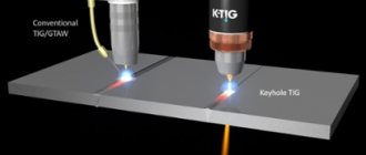
- TIG welding.
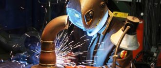
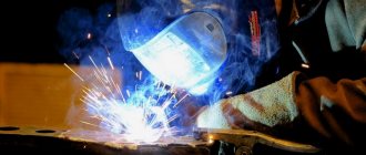
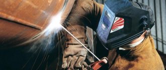
The most common is arc welding. It finds wide application both in everyday life and in industry. This type of welding process can join parts and structures made of different materials. The set of the apparatus for carrying out this process includes electrode holders, as well as a mass holder mounted on the part to be welded.
Manual arc welding is performed using electrodes consisting of a metal rod and coating, the function of which is to protect the rod and ensure the stability of the electric arc.
The assembly and manual arc welding operation sheet contains information about which electrodes can be used. There is a large selection of electrodes. With the right choice, this method can be used to weld parts made of various materials. This method allows welding in all spatial positions, as well as in hard-to-reach places. Negative aspects include low efficiency of work, low productivity, and harmful conditions. To obtain a high-quality result, this type of work can only be carried out by a welder with experience and high qualifications.
Although there are many types of electrodes, specific electrodes are used for different types of welding. There is an indication that before starting welding, the electrodes must be dried and other nuances of this process.
Manual arc welding is potentially dangerous for the welder, so much attention is paid to safety requirements.
The technological map indicates methods for preparing the edges of parts and the assembly method.
Tacks are most often specified as the assembly method.
When welding using the butt method, the shape of the bevels of the parts plays an important role in obtaining a good seam. The technological map indicates how it is recommended to make the bevel. The V-shape is used for thin sheets, and the X-shape is used for welding thicker parts.
According to the technology, the electrode along with the weld pool should be smoothly moved along the connection line at a speed that depends on the material of the parts. The recommended speed is indicated in the technological map. The basic principle is that thin parts require greater speed. For thick and massive people, a slower one would be preferable.
Based on the width of the seam and the depth of penetration, it is necessary to choose the method of moving the electrode - straight, zigzag, loop. When performing manual arc welding, the direction of movement of the electrode plays a significant role. You must choose one of three options: along the axis of the electrode, along the axis of the roller, across the seam.
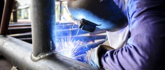
Gas welding is also carried out by the fusion method. This uses a mixture of oxygen and flammable gas. The advantages of gas welding include the ability to weld non-ferrous metals, including very thin ones. The disadvantage is the strong heating of the part.
The type of welding in which the connection occurs due to the fact that a wire is fed into the welding zone, acting as an electrode, is semi-automatic welding. Shielding gas is supplied to the same area as the electrode, the function of which is to protect the welding site from negative environmental influences. Ferrous and non-ferrous metals can be welded in this way. Another advantage is that you can weld thin and thick parts.
This type of welding is very common. A welder of lower qualifications can also cope with the work using this method, which makes a technological map for welding metal structures especially in demand. Automatic welding differs in the equipment used.
The machines used are complex equipment, therefore, in the technological map, it is important to describe its settings, which should ensure operability. There are many types of machines, so those recommended for welding a particular joint must be indicated.
TIG welding is mainly used for welding parts made of aluminum and alloys that contain it. It can also be used to connect stainless steel parts. In this type of welding, as a rule, a tungsten electrode is used, which should be reflected in the technological map.
Sample technological map for types of welding
For each welding method, there are a number of unique details that are included in the document in order to fully reflect the nuances of the future work.
We recommend reading Description of the radiographic flaw detection method
Manual arc welding with infusible and consumable electrodes
Welding with a consumable electrode (code 141) is welding in which an electric arc is the source of energy. The welder can work comfortably even in hard-to-reach places. When using non-consumable (coated) consumables (code 111), the output is better welded joints. The advantage of this method is that it becomes possible to alloy ferrous metal with workpieces that differ in structure.
| Name of organization and manufacturing facility | ||||||||
| Welding method | RD 111 | |||||||
| Code NTD, GOST | PB 03-585-03, RD 38.13.004-86, SNiP 3.05.05-84, 16037-80 | |||||||
| Main material (brand) | (M01) steel 20 | |||||||
| Standard size | Diameter – 70 mm, thickness – 5 mm | |||||||
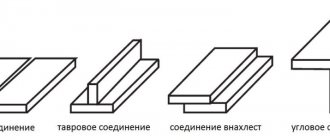
| Seam type | SS (butt weld) | |||||||
| Connection type according to NTD | T (pipe) | |||||||
| Seam position | B1 (vertical) | |||||||
| Type of connection | OS (welded on one side) | |||||||
| Tack Requirements | 3 tacks 10-15 mm long | |||||||
| Materials | Electrode SE 46 GOST 9467-75 | |||||||
| Equipment | Three-phase inverter “FORSAZH-301” | |||||||
| Connection sketches | ||||||||
| Design | Structural elements of prepared edges of parts and seams | Welding order | ||||||
| Technological parameters | ||||||||
| Roller (seam) number | I | |||||||
| Electrode or wire diameter | 3 mm | |||||||
| Type and polarity of current | Constant, reverse | |||||||
| Current strength | 80-140 A | |||||||
| Voltage | – | |||||||
| Welding time | 8 minutes | |||||||
| Electrode consumption | 6 items | |||||||
| Quality control requirements | ||||||||
| Control method | NTD code | Control volume (%, number of samples) | ||||||
| Visual and measuring | RD 03-606-03 | 100% (1 sample) | ||||||
| Radiographic | GOST 23055-78 | 100% (1 sample) | ||||||
| Date and signature of the chief engineer | ||||||||
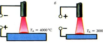
Gas arc welding
Gas shielded arc welding is a method in which gas is supplied to the melting point to relieve stress in the melt zone. The master must have a welder qualification of at least 5th category.
The technological map for welding work is filled out indicating the specific classification characteristics for code 311.
| Name of organization and manufacturing facility | |
| Way | G – gas welding |
| NTD for welding, GOST | PB 12-529-05, SNiP 42-01-2002, SP 42-101-2003, SP 42-102-2004, 16037-80 |
| Main material | Groups – I, II, III, brand – St2sp |
| Method for creating gas protection | Jet |
| Gas type | Inert |
| Electrode type | Non-melting |
| Type of current | Constant |
| Standard size | Diameter – 15-100 mm, thickness – 2-3 mm |
| Type of connection | Butt |
| Type of cutting | Without cutting |
| Connection type | C2 according to GOST 16037-80 |
| Edge preparation form | With bevel >15° |
| Sketches of construction seams and connections | |
| Quality check values | |
| Approval number and specialist signature | |
Automatic and semi-automatic using additives or gas
The degree of worker participation in the welding process is the main difference between automatic and semi-automatic equipment. Human functions when working with automation include setting up and monitoring the correct execution of tasks.
Automatic joining of materials can be performed on flux pads. Better results are obtained by using gas ones. They promote the formation of the weld root and, when working with active metals, protect the heated solid material from exposure to air. The composition of gases supplied to the pad may be similar to those used to protect the welding zone. Gas consumption depends on the composition and thickness of the working surface, joint design, and welding speed. The higher the level of quality of the seam, the more successfully it was possible to push the air away from the welding zone.
| Name of organization and manufacturing facility | |
| Way | Root of the weld: AMA – automatic argon arc welding with a non-consumable electrode. Filling and lining: AADP - automatic welding with a consumable electrode in an environment of inert gases and mixtures |
| NTD for welding, GOST | PB 03-585-03, SNiP 3.05.05-84, 16037-80 |
| Base metal | Group index – carbon steel, grade – 20 |
| Standard size | Diameter – 140 mm, thickness – 20 mm (pipe walls), 23 mm (pipe), 16.5 mm (in the welding zone) |
| Type of connection | Butt |
| Type of cutting | Single-sided, cutting angle – over 15° |
| Connection type | C10 according to GOST 16037-80 |
| Sketches | |
| Quality Control Inspection | |
| Date of drawing up the TC, signature of the responsible person | |
Regarding other types of welding work
The route map is developed by specialists for all types of welding work. In this case, additional data is indicated for each individual type according to the specifics of working with it and an unchanged list is entered, which is present in any document:
- a header where the names of the enterprise and object are reflected;
- procedure code;
- base metal parameters;
- type of energy;
- temperature conditions;
- equipment data, etc.
Standard cards
To facilitate the work of process engineers, standard technological maps for welding work are drawn up - TTK. This is a document that will be developed for each type of work and technological process. It gives a general idea, and the standard welding flow sheet is not tied to a specific job.
It makes sense to develop technical specifications for welding work in mass or multi-batch production. Carrying out welding work according to a standard flow chart simplifies the entire technological process. The number of points on the map depends on the complexity of the work being performed. The standard chart describes all the main stages of the welding process.
Definition
What is a technological map for welding work (also known as technical specifications for welding, a welding technological map, or simply a technical map)? In simple words, this is simply an instruction document issued to the welder to perform the work correctly. The technical map can also be used by a quality control specialist. Everything is written down in the technical sheet: from the type of welding to geometric calculations.
Simply put, a technical map is a “collection” of all technological features that need to be taken into account when welding. A properly developed technical map allows you to improve the quality of the welded joint and, in general, make the work of the welder or other specialists more productive and better.
The technological map was invented and implemented not so long ago, namely in the late 80s of the last century. This is due to a major technological breakthrough in the field of welding, when new modern technologies appeared and rare metals became available.
Filling out the technological map
It is convenient to fill out all the columns of the document using a sample welding flow chart. The technological map must contain information about the metal of the parts being connected, their dimensions, preparatory work, and the necessary measures for cleaning surfaces.
If preheating of parts is required, this must be reported. The sequence of actions for forming a seam should be indicated, and what equipment can be used for this specific type of work. An important role is played by information about what value the current should have, as well as the voltage value, polarity, and the speed at which the welding process should take place.
The development of a welding process sheet according to the sample will facilitate and speed up this process. The welding mode will be selected not on the basis of the welder’s experience, but according to the recommendations available in the relevant regulatory documents. At the bottom of the technological map there should be the name of the developer and his signature.
Welding process map - sample filling:
First, the object on which the welding process will be carried out is indicated. In the first column “Welding method” it is written: manual arc, gas, semi-automatic, automatic or other method. In the example given, RD(111) means “manual arc”, and in brackets is the digital code for this type of welding.
Then follows a column that should contain information about the grade of the base material from which the parts being welded are composed. This information can be found in the product design. In the column “Name (code) of NTD” enter a list of regulatory documents that must be followed during the welding process.
Then information is provided on the type of seam, its diameter and thickness, as well as the type of connection in accordance with existing regulatory documentation and the GOST applicable to it. Then there is information about the position of the seam, the type of connection, and the method of assembly. If tacks are used to securely fix the products being welded, then their number, length and height are indicated. For welding materials, the brand and standard or specifications according to which they were manufactured must be indicated.
An important column is the one where there are recommendations for choosing the equipment used, for example, a welding inverter.
An integral part of the technological map are sketches. The design, structural elements of the seam and the welding order are shown separately. The required dimensions with tolerances are indicated on the drawings.
As technological type parameters for each roller, the method by which welding should be carried out, the diameter of the electrode, the type of current and its polarity, the current strength, voltage, the speed at which the electrode should move, gas consumption and other necessary information are indicated.
Below are additional welding technology parameters:
- type of electrode, for example, tungsten;
- flux;
- shielding gas;
- method of protecting the reverse side of the seam;
- mode in which preliminary and accompanying heating is carried out;
- welding temperature;
- heat treatment mode.
Additional welding mode parameters include:
- width and thickness of the roller of one pass in millimeters;
- electrode extension in millimeters;
- the distance at which the torch nozzle should be from the workpiece being welded, in millimeters;
- vibration amplitude in millimeters;
- oscillation frequency in min-1;
- pulse mode parameter values: pulse current in amperes, pulse duration in seconds, pause current in amperes, pause duration in seconds.
Additional technological requirements for welding may include:
- Preliminary drying of the ends of parts if there is moisture on them.
- Requirements for tacks. Uniform placement of tacks for fixing products. Preliminary cleaning of tacks with a grinding wheel.
- What electrodes should be used for root weld welding and their coating.
- Grinding the root layer with an abrasive wheel.
- What electrodes should be used to weld the facing layer.
- Layer-by-layer cleaning of each layer from slag and splashes.
- Leveling rough areas of the facing layer using a grinder or file.
An important component is the methods for monitoring the resulting connection and the equipment used for this. In multi-batch production, it is necessary to indicate what percentage of products are subject to control. At the bottom of the technological map there should be signatures of the employee who developed the technological map, the one who checked the correctness of its completion, with whom the approval was carried out, with an explanation of the names and an indication of the position.
What items are present?
The technological map must contain the following information:
- Everything related to the base material of the surfaces: metal grade, parameters and chemical characteristics, steel group, data on cutting and cleaning of edges. This is the most important point of the TC. The main task of the master to minimize the risk of making a mistake is to correctly determine the type of working material. All other points of the instructions depend on this.
- Method and type of welding, parameters for installation.
- Welding equipment used.
- Temperature conditions.
- The sequence of formation of welding seams.
- Regulatory documentation for welding (NTD).
Any items can be included in the TC at the discretion of the organization or the customer.
Customer requirements
The organization or individual on whose order the work is being carried out puts forward demands for exact deadlines for completion. They are prescribed as a separate paragraph in the Labor Code after approval. The customer determines wishes for assessing the conformity of welded structures after quality control.
Work order
To optimize production, a standard algorithm of actions is provided:
- Check equipment and prepare materials. Parts are cleaned of foreign elements. The heat-affected area requires special attention so that small grains do not have a negative impact on the quality of the entire product. If necessary, grind the edges with a grinding machine or manually with a file. The groove is filled with electrode metal, the gap between the edges varies depending on the brand, thickness of the parts, type of welding, etc.
- If the gap is insignificant, the connection is made without filler material - with a non-consumable electrode. The consumable electrode welding option is provided for a wider gap. Its size is directly proportional to the depth of penetration of the edges involved. The optimal groove is the X shape, which ensures the durability of the weld and minimizes the risk of deformation of the finished weld product.
- The edges are dulled by tightly compressing the parts with a vice.
- It's time to assemble. Welding elements are fixed in different ways: with bolts, fasteners, tacks, so that the place for the future seam is as convenient as possible to work with an electrode or torch.
- After all the preparatory stages, they proceed directly to welding. This is done in different ways, for example:
- manual arc - coated electrodes or non-consumable electrode;
- mechanized - with self-protecting flux-cored wire or a consumable electrode in an environment of active gases and mixtures;
- automatic – submerged;
- gas;
- termite.
We recommend reading: What to do if your eyes hurt from welding
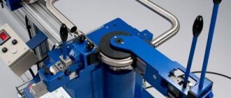
Equipment and equipment for movements
Tools for installing and moving welding machines are various lifting and retractable platforms with remote control, columns and carts.
Most of the columns are rotatable, making it possible to manipulate the device to rearrange the product. Used to install 2 types of automatic welding machines:
- non-self-propelled (allows only circular and circular seams);
- self-propelled (designed for circular, circular and straight seams).
Carts are used for circular and longitudinal. Depending on the design there are:
- bicycle;
- verbal;
- portal.
Work crew
A working (production) team of welders is a group of people who jointly conduct specialized labor activities in an enterprise on the basis of common responsibility and interest in the result. The creation of work teams can significantly speed up the pace of production of homogeneous products on a large scale. All management tasks are resolved by a specially created brigade council.
Welding specialists must be certified in accordance with PB 03-273-99.
The welder's workplace is organized according to the technical process. Collective provision of special clothing, protective masks and necessary assembly and welding equipment is provided.
What types of welding stations are there?
Before admission to production welded joints, the worker welds samples to confirm his qualifications.
On-site safety and health measures
Requirements for welding are set out in GOST 12.3.003 and the rules for the safe conduct of gas welding and electric welding work.
The welder may be exposed to such hazards as:
- electric shock;
- inhalation of harmful fumes;
- burn;
- ultraviolet and infrared irradiation;
- exceeding the permissible degree of noise and vibration, etc.
General requirements:
- Persons over 18 years of age who have passed a medical examination, received safety instructions, completed an internship and completed a verification test may be allowed to perform electric and gas welding work.
- The welder must have qualification group II in electrical safety.
- Workers are equipped with the necessary personal protective equipment, which includes:
- canvas welder's suit;
- shoes or boots;
- canvas mittens;
- safety glasses or face shield;
- workwear for winter work.
- If you discover a danger or suspect a technical malfunction of anything, you should immediately report it to management.
- Each participant in the process must perform only the work that was assigned to him.
- Hands, shoes and clothes must be dry.
- Flammable materials must be located at a distance of at least 5 m from the welding zone, and explosive materials - at least 10 m.
- If it is necessary to work at height, you should use scaffolding or ladders with special platforms covered with fire-resistant flooring and with guardrails for protection.
- Regular inspections of equipment are carried out for possible mechanical damage and negative effects of high temperatures.
- If you have to carry out welding outdoors in conditions of precipitation, then the power sources are placed in mobile sheds. Electric shock in a production environment occurs due to a worker touching live parts of equipment under dangerous voltage:
- up to 12 V – in wet conditions;
- up to 36 V – dry.
- After welding is completed, you should carefully clean the workplace and disconnect the equipment from power consumption, and hide the cylinders in a storage room.
Quality control of welded work
The welding inspection is designed to detect defects at all stages of production. Control is carried out in accordance with design, regulatory and technological documentation and consists of:
- input and operational control;
- assessment of the implementation of work done and structures created.
Through incoming inspection, the quality of materials, equipment, tools and devices is examined for compliance with all necessary standards. The results are entered into the inventory technical condition log.
With the help of an operational check, the quality of the assembly of the welded elements and the connection itself is revealed, the size and position of gaps, joints, overlaps, and tacks are taken into account.
Compliance assessment of the finished structure is carried out as the final stage upon delivery of the facility. The requirements for it are provided for by documents that stipulate:
- methods and scope of testing activities (non-destructive and destructive testing);
- testing of the finished product;
- compliance with the quality level.
Measurements and tests carried out during inspections using non-destructive or destructive methods are carried out in specialized laboratories. The methods, in turn, must be certified in accordance with GOST R 8.563.
Introductory sheet
At the end of studying the Labor Code, each worker signs a document confirming the completion of the job description: indicates the position, puts his name, date and signature. The document acts as evidence that all people involved in production will be guided in their work by the established rules and procedures, and in case of non-compliance with the regulations, sanctions will follow.
Welding of pipelines and steel pipes
Pipelines are structures of increased complexity, therefore, increased requirements are placed on their welding. This is reflected in the technological map for welding pipelines, as well as in the technological map for welding steel pipes.
Technological map of pipeline welding - sample:
The operational and technological map of pipeline welding contains:
- Card code.
- Construction object.
- Names and designations of regulatory documents.
- Pipeline type.
- Joining elements, for example, pipe with pipe, pipe with flange.
- Pipe characteristics: material grade, diameter, wall thickness, strength class.
- Welding modes of root and facing layers: current value, polarity.
- Welding materials.
- Preheating required.
The figure of the technological map for welding pipelines shows a sketch with the required dimensions.
At the bottom of the technological map for pipeline welding there is a section with additional requirements and recommendations.
conclusions
An operational flow chart is a mandatory attribute of welding work performed in production. It is difficult to expect that without it a specialist will place the correct welding seam. Quality control also becomes impossible, since there are no explicit requirements for the welding process. Accordingly, there is nothing to compare.
It is necessary to pay attention to the fact that welding cards also exist for individual technological operations. For example, there is a document on ultrasonic testing of welded joints. Compilers resort to such techniques in cases where the work is very complex and accompanied by a large amount of data.
For example, there may be one technological map for welding steel pipes, but a technical map for welding metal structures of complex configuration consists of several separate documents. It is not practical to collect all the information in one flow chart, as this will only complicate the execution. Dozens of tables and a large amount of information are inconvenient to study and be guided by in your work.
Test welded joint
In mass or multi-batch production, a connection called a control connection is made. It can be cut from existing connections or made separately from materials identical to the main one. It is easier to control such compounds and draw appropriate conclusions based on this.
The welding process map for the control welded joint is as follows:
It must indicate the base material, welding method, position of the seam, type of connection, and welding equipment used. The technological parameters of welding are indicated: diameter of the electrode or wire, current strength, voltage, time required for the process, consumption of electrodes. It is reported what method should be used to control welded products, for example, visual or radiographic.
The control connection may be subjected to destructive testing methods, which is unacceptable when testing the main connections.
Control
Inspection of edges and finished joints is carried out by the technical control service. For control, various methods can be used that identify the presence of defects - acceptable or subject to correction. If correction is not possible, the resulting connection is rejected.
There are many types of control methods. One of the most common is ultrasonic. Technological map of ultrasonic testing of welded joints:
The technological chart for ultrasonic testing of welds indicates such information as control parameters, the flaw detector used and preparation for testing.