We'll call you back in 30 seconds.
GOST R ISO 15353-2014 GOST R 55080-2012 GOST R ISO 16962-2012 GOST R ISO 10153-2011 GOST R ISO 10280-2010 GOST R ISO 4940-2010 GOST R ISO 4943-2010 GOST R ISO 14284-2009 GOST R ISO 9686-2009 GOST R ISO 13899-2-2009 GOST 18895-97 GOST 12361-2002 GOST 12359-99 GOST 12358-2002 GOST 12351-2003 GOST 12345-2001 GOST 12344-88 GOST 12350-78 GOST 12354-81 GOST 12346- 78 GOST 12353-78 GOST 12348-78 GOST 12363-79 GOST 12360-82 GOST 17051-82 GOST 12349-83 GOST 12357-84 GOST 12365-84 GOST 12364-84 GOST R 51576-2000 GOST 29117 -91 GOST 12347-77 GOST 12355-78 GOST 12362-79 GOST 12352-81 GOST R 50424-92 GOST R 51056-97 GOST R 51927-2002 GOST R 51928-2002 GOST 12356-81 GOST R ISO 13898-1-2006 GOST R ISO 1389 8-3 -2007 GOST R ISO 13898-4-2007 GOST R ISO 13898-2-2006 GOST R 52521-2006 GOST R 52519-2006 GOST R 52520-2006 GOST R 52518-2006 GOST 1429.14-2004 GOST 24903-81 G OST 22662-77 GOST 6012-2011 GOST 25283-93 GOST 18318-94 GOST 29006-91 GOST 16412.4-91 GOST 16412.7-91 GOST 25280-90 GOST 2171-90 GOST 23401-90 GOST 30642-99 GOST 25698-9 8 GOST 30550-98 GOST 18898 -89 GOST 26849-86 GOST 26876-86 GOST 26239.5-84 GOST 26239.7-84 GOST 26239.3-84 GOST 25599.4-83 GOST 12226-80 GOST 23402-78 GOST 1429.9-77 GOST 1429.3-77 G OST 1429.5-77 GOST 19014.3-73 GOST 19014.1-73 GOST 17235-71 GOST 16412.5-91 GOST 29012-91 GOST 26528-98 GOST 18897-98 GOST 26529-85 GOST 26614-85 GOST 26239.2-84 GOST 26239.0-84 GOST 262 39.8-84 GOST 25947-83 GOST 25599.3 -83 GOST 22864-83 GOST 25599.1-83 GOST 25849-83 GOST 25281-82 GOST 22397-77 GOST 1429.11-77 GOST 1429.1-77 GOST 1429.13-77 GOST 1429.7-77 GOST 1429.0-77 GOST 20018-74 GOST 18317-94 GOST R 52950-2008 GOST R 52951-2008 GOST 32597-2013 GOST R 56307-2014 GOST 33731-2016 GOST 3845-2017 GOST R ISO 17640-2016 GOST 33368-2015 GOST 10692-2015 GOST R 55934-2013 GOST R 55435- 2013 GOST R 54907-2012 GOST 3845-75 GOST 11706-78 GOST 12501-67 GOST 8695-75 GOST 17410-78 GOST 19040-81 GOST 27450-87 GOST 28800-90 GOST 3728-78 GOST 30432- 96 GOST 8694-75 GOST R ISO 10543-99 GOST R ISO 10124-99 GOST R ISO 10332-99 GOST 10692-80 GOST R ISO 17637-2014 GOST R 56143-2014 GOST R ISO 16918-1-2013 GOST R ISO 14250-2013 GOST R 557 24 -2013 GOST R ISO 22826-2012 GOST R 55143-2012 GOST R 55142-2012 GOST R ISO 17642-2-2012 GOST R ISO 17641-2-2012 GOST R 54566-2011 GOST 26877-2008 GOST R ISO 17641- 1- 2011 GOST R ISO 9016-2011 GOST R ISO 17642-1-2011 GOST R 54790-2011 GOST R 54569-2011 GOST R 54570-2011 GOST R 54153-2010 GOST R ISO 5178-2010 GOST R ISO 15792-2-2 010 GOST R ISO 15792-3-2010 GOST R 53845-2010 GOST R ISO 4967-2009 GOST 6032-89 GOST 6032-2003 GOST 7566-94 GOST 27809-95 GOST 22974.9-96 GOST 22974.8-96 GOST 22974.7 -96 GOST 22974.6-96 GOST 22974.5-96 GOST 22974.4-96 GOST 22974.3-96 GOST 22974.2-96 GOST 22974.1-96 GOST 22974.13-96 GOST 22974.12-96 GOST 22974.11-96 GOST 22974.10-96 GOST 22974.0-96 GOST 21639.9-93 GOST 21639.8-93 GOST 21639.7 -93 GOST 21639.6-93 GOST 21639.5-93 GOST 21639.4-93 GOST 21639.3-93 GOST 21639.2-93 GOST 21639.0-93 GOST 12502-67 GOST 11878-66 GOST 1763-68 GOST 13585-68 GOST 16971-71 GOST 21639.10-76 GOST 2604.1-77 GOST 11930.7-79 GOST 23870-79 GOST 11930.12-79 GOST 24167-80 GOST 25536-82 GOST 22536.2-87 GOST 22536.11-87 GOST 22536.6-88 GOST 22536.10- 88 GOST 17745-90 GOST 26877-91 GOST 8233 -56 GOST 1778-70 GOST 10243-75 GOST 20487-75 GOST 12503-75 GOST 21548-76 GOST 21639.11-76 GOST 2604.8-77 GOST 23055-78 GOST 23046-78 GOST 11930.11-79 GOST 11 930.1-79 GOST 11930.10-79 GOST 24715-81 GOST 5639-82 GOST 25225-82 GOST 2604.11-85 GOST 2604.4-87 GOST 22536.5-87 GOST 22536.7-88 GOST 6130-71 GOST 23240-78 GOST 3242-79 GOST 11930.3 -79 GOST 11930.5-79 GOST 11930.9 -79 GOST 11930.2-79 GOST 11930.0-79 GOST 23904-79 GOST 11930.6-79 GOST 7565-81 GOST 7122-81 GOST 2604.3-83 GOST 2604.5-84 GOST 26389-84 GOST 2604.7-84 GOST 2 8830-90 GOST 21639.1-90 GOST 5640-68 GOST 5657-69 GOST 20485-75 GOST 21549-76 GOST 21547-76 GOST 2604.6-77 GOST 22838-77 GOST 2604.10-77 GOST 11930.4-79 GOST 11930.8-79 GOST 2604.9 -83 GOST 26388-84 GOST 14782 -86 GOST 2604.2-86 GOST 21639.12-87 GOST 22536.8-87 GOST 22536.0-87 GOST 22536.3-88 GOST 22536.12-88 GOST 22536.9-88 GOST 22536.14-88 GOST 22536.4-88 GOST 22974.14-90 GOST 23338-91 GOST 2604.13-82 GOST 2604.14-82 GOST 22536.1-88 GOST 28277-89 GOST 16773-2003 GOST 7512-82 GOST 6996-66 GOST 12635-67 GOST 12637-67 GOST 12636-67 GOST 24648-90
- gost-3242-79.pdf (340.15 KiB)
GOST 3242-79
GOST 3242–79 Group B09
INTERSTATE STANDARD
WELDED CONNECTIONS
Quality Control Methods
Welded joints. Quality control methods
Date of introduction 01/01/81
By Decree of the USSR State Committee for Standards dated August 2, 1979 N 2930, the validity period was set from 01/01/81. The validity period was removed by Decree of the State Standards Committee of Russia dated 10/21/92 N 1434 INSTEAD OF GOST 3242–69 REISSUE. May 2002
1. This standard establishes quality control methods and the scope of their application when detecting defects in welded joints of metals and alloys made by welding methods given in GOST 19521–74. The standard complies with the CMEA standardization recommendations PC 5246−73*, PC 4099−73, PC 789−67 and the international standard ISO 2437−72. ________________ * Access to international and foreign documents mentioned here and further in the text can be obtained by following the link. — Note from the database manufacturer.
2. The use of a method or set of control methods for detecting defects in welded joints during technical inspection of structures at all stages of their manufacture, repair and modernization depends on the requirements for welded joints in the technical documentation for the structure. Control methods must correspond to those given in the table and are indicated in the technical (design and technological) documentation for the structure.
3. The admissibility of using methods not established in this standard must be provided for in the technical documentation for the design. The technology for monitoring welds by any method must be established in the regulatory and technical documentation for monitoring.
Non-destructive methods for quality control of welded joints
| Type of control | Control method | Characteristics of the method | Application area | Designation of the standard for control method | |||
| Detected defects | Sensitivity | Features of the method | |||||
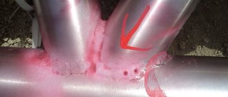
| Technical inspection | External inspection and measurement | Surface defects | Discontinuities are detected, deviations of the size and shape of the welded joint from the specified values of more than 0.1 mm, as well as surface oxidation of the welded joint. | The method allows you to detect defects of the minimum detectable size during inspection and measurement of a welded joint using optical instruments with a magnification of up to 10 and measuring instruments | Not limited | — | |
| Capillary | Colored Luminescent Fluorescent-colored | Defects (discontinuities) coming to the surface | Conditional sensitivity levels according to GOST 18442–80 | The sensitivity and reliability of the method depend on the quality of preparation of the joint surface for testing | Not limited | GOST 18442–80 | |
| Radiation | Radiographic Radioscopic Radiometric | Internal and surface defects (discontinuities), as well as defects in the form of the connection | From 0.5 to 5.0% of the controlled metal thickness From 3 to 8% of the controlled metal thickness From 0.3 to 10% of the controlled metal thickness | Detection of defects according to GOST 7512–82. Sensitivity depends on the characteristics of the weld joint being inspected and the means of control | According to GOST 20426–82 | GOST 7512–82 | |
| Acoustic | Ultrasonic | Internal and surface defects (discontinuities) | Thickness of welded joint, mm | Ultimate sensitivity, mm | The size, number and nature of defects are determined in conventional indicators according to GOST 14782–86 | According to GOST 14782–86 | GOST 14782–86 |
| From 1.5 to 10 incl. | 0,5−2,5 | ||||||
| St. 10 to 50 " | 2,0−7,0 | ||||||
| » 50 «150 « | 3,5−15,0 | ||||||
| » 150 «400 « | 10,0−80,0 | ||||||
| » 400 «2000 « | 35,0−200,0 | ||||||
| Magnetic | Magnetic fluxgate | Surface and subsurface discontinuities | Conditional sensitivity levels according to GOST 21104–80* | The method provides identification of: internal discontinuities located at a depth of up to 10 mm from the joint surface; multidirectional defects. The sensitivity and reliability of the method depends on the quality of preparation of the compound for control | According to GOST 21104–75 | GOST 21104–75 | |
| _______________ *Probably an error in the original. Should read: GOST 1770–74. — Note from the database manufacturer. | |||||||
| Magnetic powder | Surface and subsurface discontinuities | Conditional sensitivity levels according to GOST 21105–87 | The method provides identification of internal discontinuities located from the joint surface at a depth of up to 2 mm inclusive. The sensitivity and reliability of the method depend on the quality of preparation of the compound for control | According to GOST 21105–87 | GOST 21105–87 | ||
| Magnetographic | Surface, subsurface and internal discontinuities | From 2 to 7% of the thickness of the controlled metal | The reliability of testing is reduced in the presence of irregularities on the controlled surface of the joint measuring more than 1 mm. Sensitivity decreases with increasing discontinuity depth | Welded butt joints made by gas arc welding, structures made of ferromagnetic materials. Controlled thickness no more than 25 mm | — | ||
| Leak detection | Radiation | Through defects | For krypton 85 - from 1 10 to 1 10 mmMPa/s | Radioactive danger | Detection of leaks in welded joints operating under pressure, closed nuclear power structures, as well as closed structures when other leak detection methods cannot be used. Controlled thickness is not limited | — | |
| Mass spectrometric | Through defects | By method: accumulation at atmospheric pressure - up to 1·10mmMPa/s; evacuation from 1·10 to 1·10mmMPa/s; probe - up to 1·10mmMPa/s | Operating conditions for leak detectors: ambient temperature 10−35 °C, maximum relative humidity 80% | The method of pressure accumulation is to determine the total degree of leakage of closed structures. The evacuation method is to determine the total degree of leakage of closed and open structures. Probe method - detection of local leaks in welded joints of large structures Controlled thickness is not limited | — | ||
| Gauge | Through defects | By method: pressure drop - from 1·10 to 7·10mmMPa/s differential pressure gauge to 1·10mmMPa/s | The sensitivity of the method decreases when testing large-volume structures. The duration of the test, the temperature of the test gas and the environment, as well as the amount of atmospheric pressure affect the test error | Welded joints of closed structures operating under pressure: pressure drop method - to determine the amount of total leaks; differential pressure gauge method - to determine local leaks. Controlled thickness is not limited | — | ||
| Halide | Through defects | For freon 12: atmospheric probe - up to 5·10 mmMPa/s; vacuum probe - up to 1·10 mmMPa/s | The reliability and sensitivity of testing is reduced if the surface being tested has irregularities (nodules, depressions) that prevent the probe from approaching the controlled surface. | Detection of the location and magnitude of local leaks in welded joints of closed structures operating under pressure. Controlled thickness is not limited | — | ||
| Gas analytical | Through defects | For freon 12 (90%) mixed with air from 2 10 to 4 10 mmMPa/s | The reliability of the control is reduced in the presence of various vapors and gases in the surrounding atmosphere, including solvents for preparing the surface of the test joint, tobacco smoke and gases generated during welding | Detection of local leaks in welded joints of closed structures operating under pressure. Controlled thickness is not limited | — | ||
| Chemical | Through defects | For ammonia - up to 6.65 10 mmMPa/s For ammonium - from 1 10 to 1 mmMPa/s | Compliance with fire safety regulations and rules for working with hazardous chemicals is required. | Detection of local leaks in welded joints of open and closed structures operating under pressure or intended for storing liquids. Controlled thickness is not limited | — | ||
| Acoustic | Through defects | Not less than 1·10mmMPa/s | The control is carried out in the absence of noise interference. Remote control possible | Detection of leaks in welded joints of underground high-pressure water and gas pipelines. Controlled thickness is not limited | — | ||
| Capillary | Through defects | Luminescent - from 1 10 to 5 10 mmMPa/s Luminescent color - from 1 10 to 5 10 mmMPa/s Luminescent-hydraulic - from 1 10 to 5 10 mmMPa/s Kerosene wetting - up to 7 10 mmMPa/s | Thorough cleaning of the monitored surface is required. The sensitivity of the method decreases when testing large thicknesses and when testing welded joints located in all spatial positions other than the bottom. When controlled by wetting with kerosene - high fire hazard | Detection of leaks in welded joints of open and closed structures: luminescent and luminescent-colored - welded joints of structures whose working substance is gas or liquid; luminescent-hydraulic and kerosene wetting - welded joints of structures whose working substance is liquid. Controlled thickness is not limited | — | ||
| Pouring water under pressure | Through defects | From 3·10 to 2·10mmMPa/s | When inspecting large-capacity welded joints, structural rigidity must be ensured. | Detection of local leaks in welded joints of closed structures operating under pressure. Controlled thickness, not limited | Regulatory and technical documentation approved in accordance with the established procedure | ||
| Pouring water without pressure | Through defects | No more than 1·10mmMPa/s | When inspecting large-capacity welded joints, structural rigidity must be ensured. | Detection of local leaks in welded joints of open structures. Controlled thickness is not limited | Regulatory and technical documentation approved in accordance with the established procedure | ||
| Pouring with a stream of water under pressure | Through defects | No more than 1·10mmMPa/s | The sensitivity of the method increases with a luminescent indicator coating of the surface being inspected. Inspection is carried out before installation of equipment | Detection of local leaks in welded joints of open structures. Controlled thickness is not limited | Regulatory and technical documentation approved in accordance with the established procedure | ||
| Watering with a diffuse stream of water | Through defects | No more than 1·10mmMPa/s | The sensitivity of the method increases with a luminescent indicator coating of the surface being inspected. Inspection is carried out before installation of equipment | Detection of local leaks in welded joints of open structures. Controlled thickness is not limited | Regulatory and technical documentation approved in accordance with the established procedure | ||
| Bubble | Through defects | Pneumatic: air blowing - from 7 10 to 1 10 mmMPa/s with compressed air blowing - from 1 10 mm MPa/s Pneumohydraulic: aquarium - 1 10 mm MPa/s pressure aquarium - from 5 10 to 1 10 mm MPa/s Vacuum (using vacuum chambers) - up to 1·10mmMPa/s | Control is carried out with compressed air. The composition of foaming coatings depends on the air temperature when testing using pneumatic and vacuum control methods | Detection of local leaks. Pneumatic method: by air injection - welded joints of closed structures, the working substance of which is gas or liquid; blowing with a jet of compressed air - welded joints of open large-sized structures. Pneumohydraulic aquarium and pressure aquarium methods: welded joints of small-sized closed structures operating under pressure. The vacuum method is a one-sided approach to controlled connections. Controlled thickness is not limited | Regulatory and technical documentation approved in accordance with the established procedure | ||
| Opening | Internal defects | Macroscopic defects are detected | Opening is carried out by cutting, drilling, gas or air-arc gouging, grinding, as well as cutting out a section of the welded joint with the subsequent production of layer-by-layer sections from it. After inspection, welding of the exposed section of the welded joint is required. | Welded joints that are not subject to heat treatment or are inaccessible for radiation and acoustic testing. Controlled thickness is not limited | — | ||
| Technological test | Internal and surface defects | Macroscopic and microscopic defects are detected | The control test is performed using the same technological process and by the same welder(s) as the controlled welded joints. | Not limited | — | ||
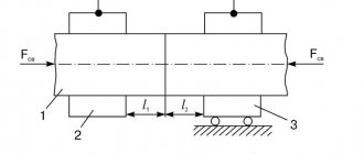
Inspection methods, sounding patterns and methods of scanning welded joints
Control methods
According to GOST, ultrasound can be performed using various methods, such as: mirror-shadow, echo-shadow, echo-pulse, diffraction, echo-mirror or delta method.
Carrying out an examination by any of the mentioned methods cannot be done without converters that are connected to a combined or separate circuit.
Pulse echo
Mirror-shadow
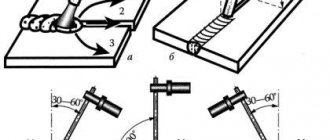
Echo-shadow direct beam (a) and inclined beams (b) probe
Echo-mirror
Diffraction
Variations of the delta method
Scanning methods
According to GOST, ultrasonic testing has two main scanning methods: longitudinal and transverse. In practice, both of these methods are combined to obtain the most accurate and extensive data on the presence of damage in the welded joint.
Transverse-longitudinal scanning options
The least popular scanning method is a swing beam, but it is also allowed by the state standard.
Swing beam method
Sounding schemes
The sound patterns for each type of weld are different. For example, according to GOST for ultrasonic testing of welds, butt joints are examined with a direct, single-reflected or double-reflected beam.
Sounding a butt seam with a doubly reflected beam
According to GOST for ultrasonic testing of welded joints, the study can be carried out with straight and inclined transducers, a direct or single-reflected beam scheme.
Scheme of sounding a fillet weld using combined inclined and direct transducers
It is worth noting that the standards allow the use of various sounding patterns in any type of welded joints that are included in the regulatory documents for control.
Pulse echo testing of intersecting welds is carried out using inclined transducers using a sounding circuit, which is shown in the figure:
Ultrasonic testing accurately detects transverse cracks. This procedure is carried out by inclined transducers with sound circuits, which are presented below:
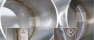
Examination of butt welded joints for the presence of transverse cracks: a) - with the weld bead removed; b) – in the presence of a seam bead