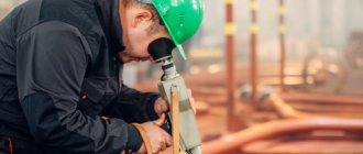
Visual inspection
This is the simplest and most primitive control method with which it is necessary to begin quality control of welds. Not all defects are deeply hidden. A significant part of them are located outside. A visual inspection will allow you to see them and, if necessary, immediately reject them, which leads to saving time and effort. It is clear that this type of control is non-destructive. With a visual inspection, it is easy to see the main geometric parameters of the weld and evaluate them.
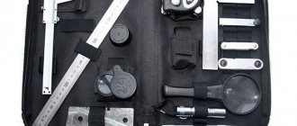
Visual inspection is not random. All welded joints made are subject to it. For a more accurate assessment, you can use a magnifying glass with higher magnification. No more devices will be needed except a caliper and templates for measuring the deviations found.
Although a visual inspection mainly determines the geometric parameters of the weld and external defects, partially external inspection can also indicate the presence of internal defects. For example, the unevenness of the surface of the rollers may be a consequence of lack of penetration inside. Such clues should be taken into account in more thorough research methods.
To make defects better visible, all dirt and slag residues are removed from the surface before starting the inspection. The seams can be treated with nitric acid, and then quickly remove its residue with alcohol.
Visual control
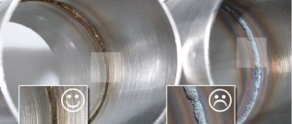
The most accessible way to determine the quality of welded joints. No additional instruments or materials are needed for external inspection. It is enough to have good eyesight and attention to detail. The welded joint must be examined as carefully as possible. We can talk about good quality only if there are no visible defects, chips, or cracks; and the seam is characterized by the same width (height) along its entire length. It is very important that there are no gross welding defects: folds, sagging, unwelded areas.
To control the quality of the weld as effectively as possible, it is worth including a good lamp, magnifying glass, caliper and tape measure in the list of tools used. These tools will be needed to find the defect, determine its size and outline ways to fix the problem. The simplest devices, of course, do not allow you to fully control the quality of welding, but they will be the first step towards this.
Capillary method
Methods of inspection of welded joints include such a popular one as capillary, also called inspection of welded joints PVK. The method is penetrant control. A special regulatory document has been developed for it - GOST 18442, which sets out the basic requirements for the use of the capillary method.
One of the main advantages of the capillary method is that it is a non-destructive method for quality control of welded joints. This method uses the property inherent in liquids to penetrate microscopically sized capillaries. To use it, you need special liquids, which are called indicators or otherwise penetrants.
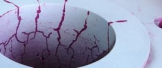
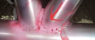
It is these liquids that have the special property of penetrating into the smallest cracks. Since they have a bright color, most often red, its traces become visible even to the naked eye without much effort. If the defect is too small, you can use a magnifying glass.
The capillary method of weld inspection is universal. It allows you to detect various defects - cracks, pores, lack of penetration, burns. The advantages of the method include its low cost - no expensive equipment is required, and penetrants are relatively inexpensive. The method allows you to determine the exact parameters of defects and their location.
Penetrant testing can be used for both ferrous and non-ferrous metals. This allows it to be used in various fields.
The following types of capillary control are available:
- basic;
- combined.
The main method is based on the use of brightly colored penetrating liquids. The combined method means the use of several welding quality control methods at once. A prerequisite is that they include the capillary method. In addition to it, methods such as induction, magnetic, radiographic can be used. As well as other methods of monitoring welds.
Each of them has its own varieties. In the main method, they are divided depending on the type of penetrating substance chosen and the option with which the information is read.
Varieties of the main method depending on the penetrating substance:
- special solutions;
- filter suspensions.
Varieties of the main method, depending on what method of reading information is used:
- chromatic;
- achromatic;
- luminescent;
- luminescent-chromatic.
The chromatic method is called color. And achromatic - brightness. Therefore, you can find the name luminescent-color method.
The divisions of the combined method depend on the option used to influence the surface being tested. In their name, the first word is “capillary”, and the continuations are:
- electrostatic;
- electroinduction;
- magnetic;
- radiation absorption method;
- radiation method of radiation.
In addition to indicators, the combined method also uses special equipment. An example of such a combination is that control is first carried out using the capillary method, and then the results are clarified using radiography using an X-ray machine.
The flaw detection technology is as follows:
- Cleaning the surface being tested.
- Drying the surface.
- Application of penetrant to the surface under study.
- Intermediate cleaning.
- Application of developer.
- Inspection of the results and rendering a conclusion.
Cleaning
Cleaning can be done using any solvent. It is necessary to ensure that there is no dirt, paint or oil stains left on the surface. You can also use sandpaper or a wire brush to clean the surface. But to control precise and critical connections that have a smooth surface, it is better not to resort to this.
Chemical cleaning is carried out using various chemicals that allow you to remove all types of dirt and stains. If chemicals remain on the surface, a reaction with the indicators may occur. To avoid this, they must be washed off the surface with water or similar means.
Drainage
Drying should occur naturally in the air. The use of napkins or towels may result in lint remaining on the surface, which will make further inspection less reliable.
Application of indicators
Indicators can be applied to the surface under study in various ways. With the capillary method, the liquid is applied by wetting, with a jet from a spray can, or by immersing the compounds in a bath with an indicator, provided they are small in size.
The vacuum method involves sucking the indicator liquid inside when a void has formed in the defect cavity, the air pressure in which has become less than atmospheric.
The compression method is the opposite of the previous one. The liquid penetrates into the defect under the influence of pressure above atmospheric. The air is displaced.
The ultrasonic method consists of filling cavities using ultrasound. The deformation method consists of exposing the penetrating liquid to vibrations of a sound wave.
Intermediate cleaning
Intermediate cleaning should be carried out in such a way as not to remove the indicator from the cavity formed by the defect. Cleaning with water is done either by spraying or wiping with damp pieces of cloth. At the same time, you should not press hard on the surface, so as not to damage it. The water temperature should be no more than 50°C.
When cleaning with solvents, first remove excess moisture with a lint-free cloth. Then clean with a cloth soaked in solvent.
Emulsifiers can be used for cleansing. They are either water-sensitive or oil-based. The emulsifier is applied to the surface after it has been cleaned with water. Then the surface is washed again with water. You can use combined cleaning - first with water and then with a solvent.
After intermediate cleaning, drying of the controlled surface must be ensured. This can be achieved by simply wiping with a lint-free, dry cloth. Excess moisture may evaporate at ambient or elevated temperatures. You can direct a stream of air at the surface being tested. A combination of these methods is allowed.
Drying must be done with extreme caution so as not to inadvertently dry out the indicator in the defective seam cavity. This provides a temperature limit of 50°C.
Applying developer
Then comes the crucial moment - applying the developer. It is applied in an even layer of small thickness. This stage should be started immediately after intermediate cleaning, so that new dirt does not appear.
Dry developer cannot be used in all cases, but only with fluorescent indicators. Apply it by spraying or electrostatic spraying. The coating should be homogeneous and uniform. Local application is unacceptable.
When using a liquid developer made from an aqueous suspension, it is either sprayed onto the surface with a special apparatus, or poured into a container and the controlled compound is immersed in it. The duration of the dive should not be too long. Then the product must be dried by blowing or in an oven.
If the liquid solvent is solvent-based, it is sprayed evenly over the surface until a thin film forms. The liquid developer may be an aqueous solution. When the product under study is immersed in it, uniform application is achieved. Spraying with special devices is acceptable. After the process is completed, drying is necessary.
Depending on the chosen method and size of the connection, the development time can range from 10 to 30 minutes.
Defect detection
Assessing the quality of welded joints should begin immediately after the developer has dried. The examination can be carried out wearing glasses with magnifying glasses or using a magnifying glass. If fluorescent indicators have been used, the test is carried out in the booth after the controller's eyes have adjusted to the darkness. If color indicators have been used, then surfaces can be inspected both in daylight and in artificial light. It is necessary to ensure that no reflections of reflected light fall on the surface.
Repeated control
Sometimes there is a need to clarify the result. Then the connection is checked again. An important condition for this is to use the same tools and methods as the first time.
Penetrant flaw detection
This principle is based on the phenomenon of drawing liquid into thin tubes due to the action of surface tension forces. The intensity of capillary filling depends on its diameter and the wettability of the material. The greater the wettability and thinner the capillary tube, the faster and deeper the liquid is drawn.
Expert opinion
Bagrov Viktor Sergeevich
Welder of the highest 6th category. He is considered a master of his craft, knows the intricacies and nuances of the profession.
Note that this method is suitable for assessing the quality of connections made of metal, plastic or ceramics.
After the liquid penetrates the capillary, all flaws reveal themselves. Special substances for performing penetrant flaw detection are called penetrants. They are characterized by their color contrast, as well as the low surface tension forces that arise. Defect cavities are filled with penetrants and become easily visible.
Currently, several dozen penetrant formulations have been developed, and they all have different properties. Some of them are made on a water basis, as well as on the basis of kerosene, benzene or turpentine. Organic liquids are most acceptable, as they increase the sensitivity of the product to the smallest defects. A special case of capillary examination is luminescence flaw detection. With this research method, luminescent substances are included in the penetrant formulation. The surface under study is irradiated with ultraviolet rays, after which the substance that has penetrated into the crack or pore begins to glow.
All substances for penetrant flaw detection are divided according to sensitivity. The highest degree is considered the first class of sensitivity. Substances of class 1 penetrate into capillaries whose diameter is 0.1 microns. There is also an upper limit value at which liquid is still drawn into the capillary. It is approximately equal to 0.5 mm. Another requirement for a capillary is that its length must be tens of times greater than its diameter.
Penetrants are usually released in the form of an aerosol. With this release form it is convenient to apply it to the surface. But the set of tools for flaw detection also includes a cleaner (for pre-treatment), as well as a developer (for forming the final pattern). The use of penetrants has its advantages and disadvantages.
- The positive aspects include the low cost of the process, the elementary nature of the technology, productivity, and a wide range of designs being studied.
- The disadvantages boil down to the need to thoroughly clean the seam, the ability to check only surface defects, and the impossibility of using the method for capillaries with a diameter of more than 0.5 mm.
Quality control of welding seams using kerosene should be classified as a permeability test, but this method is still based on capillary phenomena. It is considered the simplest and most accessible in material terms. Kerosene has high fluidity and is able to penetrate into the smallest cracks. Looking ahead, it can be noted that the capillary method using kerosene is as effective as the hydraulic method under a pressure of 3-4 kgf/mm2. It is not for nothing that some penetrants contain kerosene.
The algorithm for checking a weld seam comes down to a few simple steps. The seam is cleaned from both sides of dirt, scale and slag. One of the sides is selected for observation and covered with an aqueous solution of chalk (400 g of powder is taken per 1 liter of water). To increase the drying speed of the suspension, you can dry the seam with a stream of hot air. The reverse side of the surface is generously moistened with kerosene. It is necessary to repeat the wetting procedure 2-3 times with an interval of 15-30 minutes.
The number of repetitions and interval depend on the thickness of the metal. Wetting is carried out in any available way (rags, brush, spray gun). Kerosene leakage will become noticeable on the side covered with the chalk slurry. Over time, dark spots or streaks will appear. It is necessary to record the location of the defects immediately after their appearance, otherwise the kerosene stains will blur and it will be difficult to determine the location of the crack, fistula or pore.
The test may take several hours. The higher the ambient temperature, the lower the viscosity of kerosene. Consequently, at elevated temperatures, the process of assessing the quality of the weld will be faster. Kerosene is primarily used when testing butt joints. Overlapping seams are much more problematic to check in this way.
During the manufacture or repair of various containers, pipeline systems, pneumatic systems, not only strength, but also tightness requirements are imposed on the weld. Permeability testing can be carried out in different ways, including hydraulic and pneumatic. The main purpose of such a check is to determine the presence of through pores through which liquid or gas will subsequently exit the tank.
The test substance used is air, nitrogen, water or oil. Usually normal pressure is not enough, so excess pressure is created to make the picture of defects more clear. When using the pneumatic method, the test container is filled with gas (air, inert gas, nitrogen). The gas is brought to a pressure one and a half times higher than the working pressure. To visually observe the leak, the outer surface of the seam is moistened with a soap solution. If there is a defect, bubbles will form. If tests are carried out at negative temperatures, the soap solution is applied to alcohol.
During the test, it is necessary to monitor the pressure and not exceed a certain norm. Typically, a pressure gauge and a bypass safety valve are installed in the tank. Small tanks are filled with air and immersed in water without lubricating with soapy water. The released air will form bubbles in the water.
The pneumatic method of testing for permeability includes testing with ammonia. The seam is covered with gauze or a bandage soaked in phenolphthalein. A mixture of ammonia and air is supplied from the back side of the seam. If ammonia passes through the seam, the bandage turns red. This method is considered reliable.
The most primitive method of pneumatic control involves blowing air over the seam. The reverse side of the connection must first be lubricated with a soap solution.
To implement hydraulic control, the cavity is filled with a liquid, usually oil or water. This also means testing under pressure exceeding the operating value by 50-100%. To detect leaks, it is enough to keep the container in this state for about 10 minutes. In parallel with this, the seam and the heat-affected zone are tapped evenly with a hammer. If it is not possible to create excess pressure, then the container with liquid should be kept for at least two hours.
Leak control
Quality control of welding and welded joints includes testing for tightness. Tightness is the absence of passage of both liquid and gaseous substances. Monitoring the tightness of welded joints detects through defects through which gases or liquids can escape or penetrate inside.
Checking welds for leaks is a non-destructive type of testing. The essence of the method is to estimate the amount of liquid flowing through a through defect or gas passage and compare this value with the tolerance specified in the technical specifications. There are welded joints that must be checked for leaks. In particular, this includes inspection of pipeline welds, which are subject to special requirements.
All existing methods for monitoring tightness come down to creating excess pressure or, conversely, rarefaction of air in order to detect the place through which a leak occurs. Before you begin testing the surface, you should prepare it: clean it and degrease it. There are different methods of leak testing.
Hydraulic method
Methods for quality control of welds include testing with ordinary water. The controlled connection is filled with water and, using a pump or hydraulic press, a pressure is created one and a half or two times higher than the working one. At the same time, observe the welds. Liquid leakage means the presence of a through defect.
Pneumatic control
The test uses compressed air, nitrogen or inert gas, which is applied to the structure being tested. If it is small in size, then you can place it in water and detect the defect and its location by the bubbles coming out.
If large-sized connections are to be checked, then control can be carried out using a foam indicator, which is a solution of soap in water. At low temperatures, part of the water can be replaced with alcohol or glycerin added.
For safety reasons, a safety valve and pressure gauge are connected. By observing the pressure gauge readings, you can monitor the pressure. If there are through defects, the pressure will decrease. If the pressure exceeds the permissible level, the safety valve will reduce it.
Kerosene test
The property of kerosene is used, which is that it can rise through tubes with a small cross-section. During testing, the role of such a tube is played by a through crack or similar defect.
A solution of chalk in water is applied to one side of the joint and allowed to dry. Then the opposite side is moistened with kerosene. The time it takes to manifest itself depends on the thickness of the connection. If there is a through defect on the side covered with chalk raster, kerosene stains will be clearly visible.
Ammonia test
The seams previously subject to control are covered with a bandage impregnated with phenolphthalein. Instead of a bandage, you can use paper tape. Ammonia is then supplied under pressure. After ammonia passes through, characteristic marks remain on the tape or bandage.
Leak detector check
This method, called PVT testing of welded joints, is highly sensitive and is used to control critical structures. Helium and halogen leak detectors are used .
Methods of weld quality control
There are various types and means of technical control, they all have their own advantages and disadvantages, features and nuances. But despite the differences, they are all designed to test the seams for strength and durability. The quality of welded joints largely depends on the welder and the components used, so the outcome of the inspection can be predicted. But we still recommend quality control to be sure that the products will last a long time.
The quality of welded joints can be determined by visual inspection (perhaps the most common method), ultrasonic, magnetic, capillary and radiation (radiographic) testing; welds are also monitored for permeability. There are other methods for monitoring welds, but in this article we will list the most common and easy to use. We recommend performing operational quality control, i.e. first inspect the seam, then carry out penetrant testing and so on. However, first things first.
Visual control
Let's start with visual control. This is the easiest and fastest way to find out the quality of welds. You don't need special equipment or liquids, your attentiveness is enough. Carefully inspect the welded joint: there should be no visible defects such as cracks or chips, the seam should have the same width and height in all areas. External inspection of welding seams also allows you to check the presence or absence of lack of penetration, sagging, and uneven seam folds. All these are defects, the detection of which can safely indicate low quality of the connection. For more effective quality control of welds, we recommend using a powerful lamp and a magnifying glass; a tape measure or ruler, or a caliper would also be useful. With the help of such simple devices, you can measure the size of defects and understand what to do with them in the future.
Of course, using this method you will not be able to perform full inspection of welded joints of pipelines, welded joints of gas pipelines or other critical structures, but visual inspection will be the first operation, after which you can apply other inspection methods.
Penetrant control
Methods for quality control of welded joints also include weld testing. For this, the capillary method is used. Its essence is extremely simple: for control, special liquids are used that are able to penetrate the smallest pores and cracks, called capillaries.
Using capillary operational control, you can check the quality of any metal, with any composition and shape. Often this method is used when you need to find out the presence of hidden defects that are invisible to the eye, but there is no budget, since capillary testing is very easy to use and does not require expensive equipment.
Capillary assessment of the quality of welded joints is carried out using liquids called penetrants (from the English word “penetrant”, which means “penetrating liquid”). Such liquids have low surface tension, which is why they easily penetrate small capillaries and remain visible to the eye. Essentially, penetrants fill cavities and color defects, thereby making them visible.
Now you can find many recipes for preparing penetrant, each of which will have its own properties and characteristics. You can prepare a penetrant based on water or any other organic liquid (turpentine, benzene, this also includes the quite popular test of welds with kerosene. Such penetrants are very effective and sensitive to the slightest defects. They confidently occupy one of the leading positions among quality control methods.
Checking the tightness of welded seams
Weld testing does not end with liquids. They also need to be checked for leaks. The leak testing method has many names: leak testing, bubble testing, pneumatic testing, hydro testing and many others. But regardless of the name, their essence remains the same: detection of through defects that impair the sealing performance of the welded joint. Checking welds for leaks is performed using gases (oxygen or nitrogen) and various liquids (for example, water). The method is in many ways similar to the capillary method, but here the gas or liquid is additionally supplied under high pressure, under which they are distributed into the defective cavities and come out. This method has its own classification. There are pneumatic and hydraulic controls, and seams can also be checked using vacuum or air blowing; these are subcategories of pneumatic control. But let's talk about everything in more detail.
Let's start with the pneumatic method of quality control of seams. It involves the use of gas or air, which is directed to the connection under pressure. In this case, the seam is lubricated with a soap solution. There is also a type of pneumatic control called vacuum control, when an artificial vacuum is created using special equipment, a part is placed in it, and the seam is also pre-wetted with a soap solution. In areas with through cracks, bubbles will form, indicating the location of the defect.
When preparing a soap solution, use one bar of soap per liter of water. If you have to work at low temperatures (outside in winter), then it is recommended to replace more than half of the water with alcohol. We also recommend connecting a pressure gauge, with which you can monitor the pressure indicator and be able to notice how it will drop when defects are detected. It would also be a good idea to use a safety valve to maintain safety precautions.
The simplest form of pneumatic testing is to immerse the part in water, without lubricating the seams with soapy water or using pressure. If the seam has defects, they will make themselves known when small air bubbles begin to appear from the welded joint. This method of quality control can be called field, but it is quite effective.
There is also another type of pneumatic inspection called quality control of welds and joints using ammonia. Ammonia is supplied instead of gas or air, and the seams are pre-covered with special paper tape. Ammonia passes through the seam and if there are defects, red spots appear on the tape.
The second type of leak control is hydraulic. Here pressure is created using water or oil. This is a very interesting method, since the part is kept in liquid for 5 to 15 minutes (depending on the characteristics of the metal), while the area near the seam is tapped with a hammer, the blows should be weak. If there are defects, then upon impact, liquid will begin to flow out from the intended place with a crack or other damage.
Magnetic control
The magnetic control method uses the basics of electromagnetism. The inspector or welder, using a special device, creates a magnetic field around the seam, which emits a stream of so-called electromagnetic lines. If they are distorted, then there are defects. Distortions are recorded using magnetic particle method.
With magnetic particle welding, ferrimagnetic powder is first applied to the surface of the weld, which, when the electromagnetic line is distorted, begins to accumulate at the defect site. Because of this, magnetic inspection is only available when working with ferrimagnetic metals. Aluminum, copper, steel with a high content of chromium and nickel cannot be inspected. In general, this is a very effective, but inconvenient and expensive method, so it is used only when monitoring particularly important components.
Ultrasonic testing
The ultrasound method is very interesting. It is based on the properties of ultrasound. Ultrasonic waves are easily reflected from the edges of a crack or chip, since they have different acoustic properties. In simple words, we apply ultrasound to the seam, and if it encounters a defect along its path, it is distorted and displayed in a different direction. In this case, different types of defects distort the ultrasonic wave in different ways, so that they can be easily identified.
Weld quality control using ultrasonic devices is used everywhere, since it is a fairly effective and at the same time inexpensive method. Compared to other methods (for example, magnetic or radiation), there is no need to take into account any characteristics of the metal or purchase expensive equipment. But there are also disadvantages: ultrasonic inspection of the welded joint must be carried out by a specialist, and not by an ordinary welder.
Radiation control
Radiation weld inspection (also called “radiographic inspection” and “gammagraphic weld inspection”) is a mini version of conventional x-rays. Gamma rays penetrate the metal and all possible hidden defects are recorded on a special film. This is the most advanced and expensive method of quality control; it requires modern equipment and qualifications from the inspector or welder. Also, excessive work with such a device can have a negative impact on human health.
Recently, digital radiography has appeared, which is performed using a computer. Here, instead of film, special reusable plates are used, which are compatible with any radiation sources. But unlike classical radiation monitoring, with the digital method, images are saved directly to a computer, they can be scaled and cropped. In the future, the developers plan to make this process automatic so that human presence is not required.
Magnetic flaw detection
Methods for quality control of welded joints include such a non-destructive method as magnetic flaw detection. This method is used to control products with a ferromagnetic composition. It will help detect shallow but hidden cracks, as well as foreign inclusions.
When the integrity of the structure inside it is compromised, a kind of “dispersion zone” appears. In this case, poles are formed at the edges. On the outer surface of the welded product, opposite the internal scattering zone, it is fixed. Magnetic lines begin to bend around this zone, and it is clearly identified. At this point, the magnetic field density changes.
Magnetic testing of welds is based on the formation of a magnetic field, which, during testing, penetrates the welded joint. For this, special equipment is used. Using flaw detectors, it is possible to detect microscopic cracks with a thickness of up to 0.001 mm. The essence of the method is that the magnetic flux, traveling along the welding seam, bypasses it when a defect appears along its path. This is a consequence of the fact that the magnetic permeability in this place is much less than the magnetic permeability of the metal itself.
To detect longitudinal cracks, a circular type of magnetization is used, and for transverse cracks, a longitudinal type is used. There is also a combined method.
Inspection of welds using magnetic metallography can be carried out in several ways.
Magnetic particle
Welding is checked using magnetic powder, which is a collection of tiny particles of magnetized metal. As a result of the influence of magnetic field scattering, these particles change their position in space.
This method can be used to control the quality of pipeline welded joints.
Typically, the ferromagnetic powder is iron. It can be used in the following forms:
- dry;
- water emulsion;
- oily suspension.
The verification process is that the powder particles, which are affected by electromagnetic fields, move evenly over the surface. When they encounter a defect on their way, powder particles begin to accumulate, forming peculiar rollers in such places. Their shape and size make it possible to judge the corresponding parameters of the found defect.
Technological operations for performing the magnetic particle method:
- Surface preparation. Cleaning it from dirt, slag, scale, traces of splashes, sagging.
- Applying a powder, emulsion or suspension to the surface of the compound being tested.
- Inspection and identification of areas with defects.
- Demagnetization of the surface.
The most reliable results can be obtained when using dry powder. To correctly assess the sensitivity of the powder, control samples are used. It is allowed to use different types of flaw detectors: stationary, mobile, portable, portable.
Magnetographic
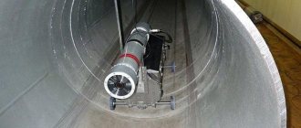
Magnetic flaw detection is a non-destructive type of weld inspection. The essence of the method is that magnetic fluxes that appear in magnetized products in the presence of defects are identified.
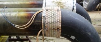
To implement this method, the surface under study is magnetized along with a magnetic carrier pressed to it using an elastic tape. At the same time, the process is recorded on magnetic tape. Information about the magnetic relief from the tape is read by special devices that are components of flaw detectors.
Most often this method is used to control welded joints of pipelines. The main advantage of this method compared to the magnetic particle method is higher productivity.
Induction control
The difference between this method and the previous ones is the presence of induction coils, with the help of which electromotive force is generated. To record the signal, the induction coil must be connected to the recording device. It can be used as a galvanometer or a signal lamp.
Control is carried out by moving the welded joint along the induction coil. Movement can also be accomplished by moving the flaw meter along the joint. When the moment of intersection of the induction coil with the place where the defect is located comes, due to a change in the magnetic flux in this place, an electromotive force appears. The induction current is supplied to the recording device.
Non-destructive testing methods
At the moment, the following non-destructive methods are distinguished:
- visual inspection;
- radiation method;
- magnetic research;
- ultrasonic method;
- capillary method;
- permeability control.
Visual inspection
Any quality control of welded joints begins with a simple external inspection. This is often enough to identify both external and internal gaps, plus there is no need to use non-destructive testing equipment. For example, different seam heights may indicate lack of penetration in different areas. Before inspection, the seams are cleaned of process contaminants, namely slag, scale and metal splashes.
Visual inspection of the weld
To make minor defects more visible, the surface is treated with an alcohol solution, and then with a 10% solution of nitric acid. After this procedure, the surface will become dull and show pores and cracks.
The main thing is not to forget to clean the acid with alcohol after troubleshooting the seam.
Inspection is the main way to identify geometric deviations, such as pores, cracks, sagging, undercuts. This test point can be carried out more efficiently using additional instruments.
To do this, it is best to use a magnifying glass, as well as better lighting, preferably with a mobile light source. A magnifying glass will allow you to detect cracks and pores that are hidden to the eye, as well as trace their path. To control the width of the rollers, you can use measuring instruments such as a ruler or caliper.
Tools for visual inspection
Radiation flaw detection
The radiographic method of testing welded joints exists in two variations:
- x-ray radiation;
- gamma radiation.
The simplest way to identify weld errors is to illuminate the product with X-rays. They have the property of penetrating through metal objects, while acting on photographic film. Thus, the resulting image is a direct map of most of the defects. Using penetrating rays, slag inclusions, gas pores, edge displacements, burns and other gaps are identified.
Slag inclusions on x-ray
Before starting work, the area under study and the adjacent plane must be properly cleaned. To do this, remove slag, splashes, scale and other defects. Also, before x-raying, an inspection is mandatory and if low-quality areas are identified, they must be eliminated.
It is prohibited to start candling in the presence of external defects, since the procedure is intended to diagnose and identify hidden defects.
If errors are detected, the decision to accept or rework a specific part lies with the regulatory documentation. It is the established rules and instructions that make it possible to determine whether errors fall within the standards established for a given product.
We recommend! Possible causes of welding electrodes sticking
To carry out the procedure, the X-ray tube is positioned so that the beam hits the suture at a right angle. On the other side of the product there is a cassette with X-ray film. Since existing defects have less impact on X-ray transmission, they will be visible as darker areas on the film. The radiographic test lasts depending on – film quality, thickness and focus. Afterwards the film is developed and you can see the result of welding.
Radiographic monitoring does not reveal:
- any discontinuities and inclusions with a size in the direction of transmission less than twice the control sensitivity;
- lack of penetration and cracks, the opening plane of which does not coincide with the direction of transmission;
- any discontinuities and inclusions, if their images in the photographs coincide with the images of foreign parts, sharp corners or sharp changes in cracks of the metal being scanned.
Gamma radiation is practically no different in operating principle from X-rays. These are radioactive rays that can penetrate metal and react to its unevenness. Using this method, I inspect from 10 to 25% of all seams; if the structure is critical, then all seams. Various chemical elements suitable for certain metals are used as a radiation source:
- Cobalt – 60 (steel, cast iron, copper, bronze and brass up to 25 cm thick), thanks to its rigid penetration, the element is suitable for most steels and large thicknesses;
- Cesium – 137 (steel up to 10 cm);
- Iridium-192 (steel up to 5 cm, aluminum up to 10 cm);
- Thulium-170 (steel and aluminum up to 20 cm).
With a decrease in penetration, the type of alloys and their thickness decrease, but at the same time the average image quality remains and makes it possible to determine the main defects.
Portable X-ray machine MART-250
Unlike X-rays, gamma rays have a number of advantages:
- isotopes remain functional for a long time;
- lighter equipment;
- possibility of troubleshooting complex components;
- increased ray permeability;
Important! Both types of radiation are extremely dangerous for humans. That is why only specially trained employees wearing a full set of protective equipment can be allowed to work. The location and operation of penetrating equipment must also be protected; lead plates, screens and other means are used for these purposes.
Magnetic flaw detection
This control of welded joints is based on the property of magnetic lines of force to respond to changes in the thickness of the metal. By recording such deviations with special instruments, it is possible to accurately detect errors in the thickness and on the upper part of the alloys.
We recommend! How to learn to cook with electric welding yourself
There are currently three variations of the method:
- magnetic powder;
- magnetic induction;
- magnetic-graphic.
Powder testing consists of applying dry powder or emulsion to the surface, going beyond the seam joint, then magnetizing the alloy and determining inaccuracies.
If the “dry method” is taken, then iron scale or oxides act as powder. The product is magnetized using an electromagnet, solenoid, or by applying current to the product. Afterwards, lightly tapping with a hammer, give the powder the opportunity to take its position. The excess is removed with a jet of air and then the flaws are fixed. The last step is demagnetization. In the wet method, magnetic powder is mixed with kerosene or special oil. The resulting suspension is applied to the seam, and its mobility, dispersion or accumulation of powder are direct identifiers of errors.
Magnetic flaw detector
With the induction method, all data is recorded by an induction coil. Special devices - flaw detectors - record magnetic scattering in metals up to 25 mm thick.
Graphic consists of fixing magnetic fluxes on a special tape. It is attached along the seam, and then the deviations are determined on the screen of the cathode ray tube.
Magnetic methods are only suitable for ferromagnetic alloys; other metals cannot be studied in this way.
Ultrasonic testing method
Along with the previous method, ultrasonic flaw detection makes it possible to record deviations formed when waves are reflected from the boundaries of media with different properties.
The ultrasonic source sends out a signal that is reflected when it reaches the end of the alloy. If a signal encounters a defect along its path, this is reflected on the wave, which in turn is recorded by the device. Different defects have their own reflections, so determining the nature of the defect is quite simple.
Ultrasonic flaw detector
Of the methods already described, this one is considered the most convenient to use. This is due to the ability to identify flaws both on the surface and in the depths of the metal. Also, the method does not have such strict restrictions as magnetic. There are a number of coarse-grain metals, such as cast iron, that are not amenable to ultrasonic examination, but for all other alloys it is possible to easily control the quality of welding work.
We recommend! Welding seams in various spatial positions
There is another drawback - the difficulty of deciphering the received data. Unfortunately, flaw detectors provide the user with very specific data that must be deciphered. It is almost impossible to do this without preliminary preparation, so a trained specialist is needed for the work.
Penetrant flaw detection
This method is based on the properties of liquids with low surface tension. Such liquids do not form large drops in one place and tend to drain, but at the same time they are able to fill the smallest grooves and holes. Surface defects and, in rare cases, through channels are determined in a similar way.
Penetrant flaw detection
A special solution is applied to the seam, which instantly fills all grooves, pores and other small defects. Then, examining the seam, you can find large flaws. For greater convenience, liquids are tinted with dye, luminescent and other coloring additives are added.
Welding quality control for permeability
The method is a logical continuation of the capillary method. The main idea is that by using fluids with deep penetration properties, it is possible to identify through-grooves in the weld.
To do this, take simple kerosene, apply it to one side of the seam, and fix wet spots on the other, signaling through channels. Among the disadvantages, it is worth noting the need to thoroughly clean the surface and maintain precision at all stages to avoid accidental contamination of the opposite side of the weld.
Ultrasonic testing
Ultrasonic quality control of welded joints of metal structures is a non-destructive method. It is suitable for testing welds of various metals. There is a search for structures whose physical and chemical properties differ from the specified ones. Exceeding the permissible dimensions is also considered a deviation.
The ultrasonic method is based on the ability of ultrasonic waves to easily reflect from the edges of cracks and chips due to the fact that their acoustic properties are different compared to the main surface. When ultrasound is applied to a weld, when it encounters a defect, it undergoes a change and begins to be reflected in a different direction. The distortion of the ultrasonic wave occurs differently depending on the type of defect, which makes them easier to identify.
Ultrasonic testing of welds is based on the penetration of a diagnostic wave deep into the metal and, when encountering defects, changing the direction of its movement. This deviation is seen on the device screen by the welding controller.
According to the readings of the diagnostic device, a characteristic is given to the identified defect. By the time during which the ultrasonic wave propagates in the metal, one can judge the depth of the defect, and by the amplitude of the reflected pulse, one can judge the size of the detected defect.
Checking the quality of welds using the ultrasonic method based on GOST-23829 is carried out in various ways:
- shadowy;
- mirror-shadow;
- pulse echo;
- echo-mirror;
- delta method.
The shadow method involves the use of two devices located on opposite sides of the metal structure under study. They are installed in a plane perpendicular to the welded connection. The purpose of the first of them is to emit waves, and the second is to receive them. The first is called an emitter. It generates acoustic waves. The second one is called the receiver. Its task is to register acoustic waves passing through the object under study.
The relative position of the emitter and receiver is important. They should be opposite each other. If there is a “dead zone” between the emitter and the receiver, then the ultrasonic vibrations may disappear or decrease. This section of the seam is considered defective.
The mirror-shadow method is approximately the same shadow method with one difference - the emitter and receiver are not located on opposite sides of the metal structure, but on the same side. With this arrangement, it is not the direct wave flow that is recorded, but the one reflected from the second surface, which is like a mirror. The defect is assessed by the value of the attenuation coefficient of the reflected vibration.
With the pulse-echo method, acoustic waves are directed to the welded joint and the wave reflected from the defect located in it is recorded. The same converter is used as the source and receiver.
The echo-mirror research method is otherwise called “Tandem”. This name is explained by the fact that when using it, two devices are used at once. Both converters are placed on the same side of the connection. Ultrasonic vibrations generated by the emitter are reflected from the defective area and are then recorded by the receiver. This method is widely used to detect vertically located cracks.
The basis of the delta method, related to ultrasonic testing, is the property of defects to emit radiation into the weld. The energy emitted from defective surfaces is monitored. To carry out such control, equipment and its configuration are required, as well as lengthy decoding of the results, so this method is not particularly popular.
Operational quality control of welded joints using an ultrasonic method is as follows:
- Cleaning the surface being tested. Traces of rust, paint residues, varnish, and various stains are removed.
- Treatment of tested surfaces with machine or transformer oil.
- Checking the functionality and adjusting the equipment used to the required parameters. Standard settings can be used if the thickness of the weld does not exceed 2 centimeters. Otherwise, it is necessary to use special diagrams.
- Carrying out quality control of welds. In this case, the emitter is moved along the connection in a zigzag manner and turned at a small angle along its axis. The finder is moved until it begins to pick up signals.
All detected deviations are recorded in a special journal. Control and verification must comply with the requirements of current regulatory materials. The ultrasonic method requires highly qualified workers who perform inspection of welded joints according to it.
Inspection of welded joints using the ultrasonic method involves finding the following defects:
- presence of pores inside the seam;
- laminated areas of metal deposits;
- cracks;
- unevenness;
- lack of penetration;
- non-fusion;
- fistulas;
- corrosion;
- oxide damage;
- sagging;
- change in chemical composition;
- mechanical damage;
- change in geometric dimensions.
Various types of connections can be subjected to ultrasound diagnostics. Such a parameter as the sensitivity of the ultrasound method can be determined by the smallest size of the defect that it can detect. The advantages include the relative safety of control operations. Thanks to the availability of mobile flaw detectors, field testing is possible.
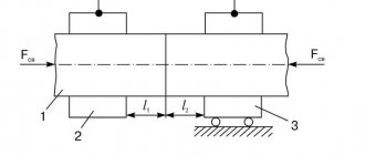
Requirements for the assembly of gas equipment pipelines
Edge offset. The permissible displacement of the edges of the welded pipes should not exceed 0.15S + 0.5 mm, where S is the smallest wall thickness of the welded pipes.
Welding joints of pipes of different thicknesses or pipes with connecting parts and fitting pipes is allowed without special processing of the edges with a wall thickness of less than 12.5 mm (if the difference in thickness does not exceed 2.0 mm).
On overhead and internal low-pressure gas pipelines, it is allowed to make pipe-to-pipe lap joints of dimensions d 50×40, 40×32, 32×25, 25×20 mm, provided:
— the gap between pipes connected with an overlap is no more than 1-2 mm and is equal in size around the perimeter;
— the amount of overlap along the length of the connected pipes is at least 3 cm;
— at the end of a pipe of smaller diameter, a chamfer is made inward at an angle of at least 45° throughout the entire thickness of the pipe wall;
Requirements for displacement of longitudinal seams
Assembly for welding of pipes with a one-sided longitudinal or spiral seam is carried out with the displacement of the seams in the places where the pipes are joined by at least:
15 mm - for pipes with a diameter of up to 50 mm; 50 mm—from 50 to 100 mm; 100 mm diameter St. 100 mm.
When assembling pipes for welding, the seams of which are welded on both sides, it is allowed not to displace the seams, provided that the intersection of the seams is checked by physical methods.
Radiation control
Weld quality control can be carried out using radiation methods. Its purpose is to identify defects located inside the joint and in the heat-affected zone. Such defects include pores, lack of penetration, foreign inclusions, and cracks.
Illumination of welds with X-rays and gamma rays allows them to penetrate inside through opaque barriers. Radiation testing of welded joints is a non-destructive type. It is based on the use of radiation called ionizing radiation. During testing, ionizing radiation is recorded and analyzed after its interaction with the surface under test.
Having penetrated inside, the radiation begins to weaken and dissipate. The magnitude of these changes depends on the thickness and density of the metal. The film emulsion is affected, causing individual elements to glow. The intensity will be greater in areas that have lower thickness or density. In particular, this applies to defects such as discontinuities or non-metallic inclusions.
Ionizing radiation is radiation that, when interacting with the environment, leads to the formation of electrical charges. To control the welds of metal structures, photons or neurons are used as ionizing radiation. The most popular is X-ray radiation. This is because it provides the most sensitive weld control.
The radiographic method of weld inspection involves the use of X-rays. A special apparatus is installed at the welded joint. X-rays penetrate metal. If there are no defects, they do not come out. If they are present, the rays go out. A special device records the path of the rays and produces a picture. In this picture you can see the size of the defects and their location.
Equipment for quality control of welded joints using the radiographic method - X-ray machine. Its main element is an emitter that generates rays. Such an emitter looks like a vacuum vessel containing an anode and a cathode.
It is necessary to select a suitable X-ray machine taking into account the thickness of the metal that is supposed to be tested. You should also take a responsible approach to choosing the film on which the research result will be recorded. It can also be seen on the monitor screen during the inspection process. Before use, each new batch of film and preparations for its processing must be checked for compliance with the requirements imposed on them.
When carrying out radiographic testing, in addition to the X-ray machine, a flaw meter is used - a metal plate with grooves of varying depths.
The images obtained as a result of radiographic testing are called x-rays. With gamma radiation - a gammagram, and control - gammagraphic control of welded joints.
The advantages of the radiographic method include:
- good sensitivity;
- clarity of the results obtained;
- ability to control various metals;
- the ability to detect the smallest defects;
- determination of linear dimensions;
- finding out at what depth the defective area lies.
Digital radiography can be performed using a computer.
How to choose a welding current
Calculation of manual arc welding modes is carried out taking into account the setting of the main current parameters, namely type, polarity and strength. Depending on the type of current, it can be alternating or constant. Polarity is divided into forward and reverse.
When considering the main parameters of the welding mode, it is worth paying attention to the magnitude of the current. It is selected using certain tables. The current indicator is determined in accordance with the thickness of the welded steel products and welding wire. But the exact adjustment indicators are determined depending on the type of arc and connection. It is worth considering that the stronger the current, the higher the temperature readings under the base of the arc will be. This will all affect the speed of welding work.
Carrying out welding technology using high current and very thin welding wire can cause overheating and splashing of molten metal. If elements that are too thin are used, this mode can lead to their burning.
When using a weak current, the arc may break and become unstable. As a result, the connection is of poor quality, and many zones with lack of penetration are formed. For this reason, many welders do not recommend using this mode.
Important! The depth of the weld pool depends on the type of current used. If the equipment is used on alternating current, then the penetration depth will be 15% higher than that of alternating current.
With straight polarity, strong heating of the metal product is observed. For this reason, this polarity is recommended for welding thick elements, because more melting of the metal is required to form a high-quality joint. If straight polarity is used for thin parts, they will quickly burn out and the seam will be of poor quality. For thin products it is worth using current with reverse polarity.
Destructive testing
All types of weld inspection are divided into non-destructive and destructive. Before starting research, it is necessary to decide which methods include destructive testing of welded joints, and whether this is acceptable in a particular case.
Destructive testing methods for welded joints include:
- mechanical testing;
- chemical;
- physical;
- metallographic.
It is advisable to carry out destructive testing of welded joints on control samples as a preliminary assessment of the condition of the welded joint.
Metallographic studies involve drilling the surface and etching it with a solution containing ammonium and copper chloride. Drilling is done through the weld. Then they go deeper into the base metal. Then the inspection site is examined with the naked eye or with a magnifying glass.
During chemical analysis, it is established that the composition of the metal and the weld on it comply with regulatory requirements. GOST 122-75 specifies methods for sampling. For mechanical studies, samples are specially made or cut from a welded joint, and tests are carried out on them.