- Materials for magnetic particle testing produced by ELITES® Russia
- Elitest indicator materials
- Ready-made black and luminescent magnetic suspensions, Elitest concentrates
- Luminescent magnetic powder Elitest, basis for preparing a magnetic suspension
- Means for processing the controlled surface
- Magnetic particle non-destructive testing
- Review of the magnetic testing method using the example of its application in aviation
- What is the basis for detecting dangerous cracks?
- Physical basis of the magnetic testing method
- Preparing parts for inspection
- Methods for magnetizing test objects
- Circular magnetization
- Longitudinal (pole) magnetization
- Contact magnetization
- Demagnetization of parts after testing
- Magnetic indicators
- Imaginary defects
- Limitations of the magnetic particle testing method
Materials for magnetic particle flaw detection produced by ELITES® Russia
Production of flaw detection materials for magnetic particle testing. Magnetic powder, ready-made magnetic suspension and the base for its preparation, primer paint - consumables for magnetic particle flaw detection, produced in Russia under the ELITES® brand, can be purchased from our dealers.
Indicative materials for IVD
Black and luminescent magnetic suspensions, concentrates
Suspension "Elitest ChS2"
Suspension "Elitest LS4"
Con
Means for processing the controlled surface
Primer paint. "Elitest BC5"
Elitest P10 cleaner
How to apply the indicator: all types of methods
When carrying out this control method, a variety of means can be used, but most often they come down to dry, wet and pasty.
Dry indicator
Typically, it is a mixture of fine metal filings that is applied in its natural state, without dilution with anything. For application, an aerosol package is used, it is possible to use a sieve for dispersion, as well as a bulb to direct the flow. Babbitt, magnetite, iron scale and similar materials that have the ability to be well magnetized are used as magnetic particle indicators. To create a magnetic field, take a U-shaped electromagnet, which is connected to an alternating or direct current source. To conduct the study, sources of 300–600 amperes are selected.
This method of magnetic particle testing of welded joints is effective for detecting the following defects:
- Seam discontinuities;
- Subsurface defects;
- Slag inclusions on the surface.
Wet indicator
In this case, a magnetic suspension is added to kerosene, a solution of liquid soap, transformer oil, water with anti-corrosion agents, or a polymer concentrate. The product is applied using a brush, by pouring the indicator onto the area being tested, and also by immersion if the element is relatively small and can be detached.
The wet technique clearly demonstrates discontinuous areas on the tested welded joints.
Magnetic particle testing (magnetic testing, magnetic particle / magnetic flaw detection, MPD)
Magnetic particle non-destructive testing is one of the methods for detecting metal defects that lie directly below the surface and extend to it. The MTD method is based on the occurrence of magnetic field inhomogeneity in places of discontinuity of ferromagnetic material (steel and iron-based alloys). At the first stage of magnetic particle testing, a residual or applied magnetic field is created in the part. Then the surface of the controlled product is treated with special flaw detection agents - magnetic powders and suspensions. Under the influence of electromagnetic forces, the particles of the powder or suspension are magnetized and linked together into chains.
Magnetic powder with a particle size of 1 micron can act as a flaw detection material Powder particles have pronounced ferromagnetic properties and can be tinted with an active pigment - phosphor (luminescent magnetic powder). But most often, in magnetic particle testing, a ready-made magnetic suspension is used - a suspension of magnetic particles. Oil (for example, Elitest ML1) or water is chosen as the basis for the suspension, depending on the control conditions and the type of equipment. As a result of the action of the magnetic field over the defects, a curvature of its direction occurs. Magnetic particles accumulate in such places, forming an indicator pattern that is visible under ultraviolet lighting (fluorescent control) or under normal lighting (in this case, primer paint can be used as a background).
The described phenomena form the basis of magnetic particle flaw detection .
Features of the method
To successfully detect surface damage and those lying at a depth of 0.5 mm, the object under study must be magnetized. Then a certain part of the magnetic flux lines, which does not change its direction over the surface without flaws, “goes” beyond the object and returns back over the damaged areas with reduced magnetic permeability.
Poles appear above them, forming a local magnetic field. Its heterogeneity concentrates the field lines over the damage area, where magnetized particles of the indicator substance are attracted to each other and form chain or linear structures along the magnetic field lines.
For successful detection of damage, a prerequisite is the perpendicular location of the affected plane in relation to the magnetic flux flow, as well as the presence of factors affecting the sensitivity of magnetic particle flaw detection:
- Coercive force
- Certain roughnesses on the surface under study
- High magnetic permeability
- Magnetizing field strength
- High-quality flaw detection material
- Sufficient degree of illumination
Certification and training of non-destructive testing specialists
Magnetic particle flaw detection
Review of the magnetic testing method using the example of its application in aircraft manufacturing.
In addition to diagnosing individual elements at the stages of production and maintenance, the magnetic particle method makes it possible to control parts and assemblies directly in the structure. The simplicity and effectiveness of the method ensured its widespread use at aircraft repair enterprises and combat units of the Air Force of the Russian Federation.
Fatigue cracks, grinding cracks, thermal cracks, hairline cracks and other defects may occur in steel parts and assemblies of aircraft equipment. During visual observation, these defects are not detected even with a magnifying glass. The magnetic particle method allows you to effectively detect defects invisible to the eye.
To solve a number of problems, magnetic particle testing has advantages that distinguish it from other non-destructive testing methods. Just like penetrant testing, magnetic flaw detection allows you to detect surface defects in materials, but the sensitivity of the control will be much higher. With capillary inspection, defects located close to the surface are not detected. There is no such limitation for magnetic particle flaw detection.
What is the basis for detecting dangerous cracks?
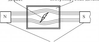
The method is based on the detection of magnetic stray fields arising over defects in steel parts by ferromagnetic particles suspended in liquid or air. During inspection, the part is magnetized using special equipment - magnetic flaw detectors. In large industries, such devices are semi-automatic lines for magnetic particle testing, operating on a conveyor principle.
Physical basis of the magnetic particle non-destructive testing method
When a test object is magnetized, a magnetic field arises. The magnetic flux comes out of the part only in places of cracks, forming a stray field. In this case, magnetic poles appear at the edges of the cracks. When magnetized by a constant (rectified) magnetic field, the magnetic flux in the part and the stray field remain.
Ferromagnetic particles entering a magnetic field are magnetized and, under the influence of magnetic forces, are connected to each other into chains. Forces also act on particles:
- addictive;
- the force of gravity;
- the buoyant force of the liquid;
- friction force;
- electrostatic repulsion.
Under the action of the resulting force, particles are attracted to the crack and accumulate above it. Let's lower the part into the suspension and look at the process of powder deposition over the crack:
Particles connected in chains above the crack form a roll of magnetic powder, which is used to determine the presence of a defect.
Preparing parts for inspection
Before testing begins, corrosion products, scale, oil and other contaminants are removed from the surface of the product. Paint reduces the sensitivity of the method, so when preparing parts for testing, it is removed. When the thickness of the paint layer is more than 0.1 mm, the scattering field is practically confined to the paint layer and defects are not detected.
If a black magnetic suspension is supposed to be used as a flaw detection indicator, then to ensure the necessary contrast when observing the results, white primer paint is applied to the controlled surface.
Magnetization methods
The key factors for choosing magnetization conditions are: the size and shape of the object, the orientation and nature of the expected defects, the presence of paint and varnish coatings and the magnetic properties of the product subject to magnetic particle testing. It should be taken into account that a magnetizing field located perpendicular to the direction of the suspected defects is the best condition for their detection.
For magnetic particle testing, the following types and methods of magnetization ( O —object of inspection; F —magnetic flux; I —electric current):
| Type of magnetization | Magnetization method | Magnetization circuit |
| Circular magnetization | By passing current through a toroidal winding | |
| By passing current throughout the object | ||
| By passing current through a section of the part | ||
| By passing current through a conductor placed in a through hole in an object (along a rod) | ||
| By inducing current in an object | ||
| Longitudinal (pole) magnetization | Using permanent magnet | |
| Using an electromagnet | ||
| With solenoid | ||
| By moving a permanent magnet over an object (contact) | ||
| Combined magnetization | Using an electromagnet and passing current through an object | |
| Using a solenoid and passing current through the object | ||
| By passing two currents through the part in mutually perpendicular directions | ||
| By inducing a current in an object and passing the current through a conductor placed in a through hole in the object | ||
| Magnetization in a rotating magnetic field | Using a rotating magnetic field solenoid |
Circular magnetization
Ring-shaped parts are magnetized by passing current through a toroidal winding . In this case, radial defects are detected on the end surfaces, and longitudinal defects on the internal and external surfaces.
Magnetizing parts by passing current through them is effective for detecting defects located on the outer surface. Such magnetization makes it possible to detect hairlines, longitudinal cracks and other defects.
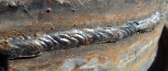
Magnetization by passing current through a section of a part is effective in inspecting welded joints. In this case, cracks are detected that propagate along the lines connecting the installation points of electrical contacts. Circular magnetization of non-removable parts is carried out using a cable and a mobile flaw detector - a powerful step-down power unit capable of generating currents of up to 10,000 Amperes. In this case, cracks are detected on parts directly in the aircraft structure.
Rod magnetization is effective for detecting defects located on the outer surface.
Longitudinal (pole magnetization)
For pole magnetization, mobile, attached, stationary and portable solenoids are used. And also electromagnets. With pole magnetization, there are some features during powder deposition. Let us limit ourselves to considering the field only in the interpolar space of the electromagnet.
Magnetic field lines run along the part. In this case, the scattering field above the crack consists of two regions.
Region 1, in which the density of field lines increases, and region 2, in which the density of field lines decreases as it approaches the surface of the part. As the current decreases, the magnetic field lines are deformed and the polarity of the crack edges changes. Area 2 is now located on the other side of the crack.
Particles in area 1 accumulate, and from area 2 they are pulled out and deposited either above the crack or in areas outside area 2. In area 2, a non-deposition zone A is formed. These zones are most noticeable when parts are dusted with magnetic powder in a chamber (air-suspension pollination method) . In this case, clear boundaries of non-deposition zones are visible near the cracks.
Non-destructive testing of welded and soldered joints of the following types was applied and compared:
- — visual inspection (VIC);
- — magnetic particle, magnetic flaw detection (MPD);
- — color (capillary) flaw detection (CD);
- — eddy current testing (VC);
- — ultrasonic testing (UK) in automatic and manual modes;
- — radiographic control (RC);
- Additionally, metallographic studies were carried out
Visual inspection (VII)
When examined through a 10x magnification loupe (XI), the presence of cracks with an opening width of 0.1 mm to 1 mm was confirmed. The disadvantages of this method include a large amount of time and a high degree of influence on the detection of human factor defects.
Magnetic flaw detection (MPD) and color (capillary) flaw detection
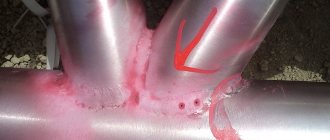
Non-destructive testing of welded and soldered joints using magnetic flaw detection (MPD) and CD methods was carried out sequentially on the same sections of the samples. Indicator marks were identified, characteristic of cracks in the middle part of the welded joint, oriented along the weld on both the outer and inner surfaces. It has been established that for identifying cracks in welded joints made by high-frequency testing, the preferred method is: Magnetic flaw detection (MPD), since it is less demanding in terms of the quality of surface cleaning, is more sensitive to defects and requires lower costs for preparing the welded joint (Fig. 1).
Eddy current testing (EC)
Eddy current testing was carried out with an eddy current sensor built into the UD3-103 flaw detector. Signals from all cracks identified by the MTD method were recorded. The amplitudes and shapes of the signals from the cracks corresponded to artificial defects with a depth of 0.2 mm, 0.5 mm and 1.0 mm. At the same time, signals similar in shape and amplitude were recorded from acceptable risks inherent in these objects. The positive side of VC is the ability to indirectly determine the depth of defects from the signal amplitude.
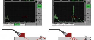
Ultrasonic testing (UK) in automatic and manual modes
The ultrasonic flaw detection (UF) method was carried out in automatic mode using the Skaruch installation. In this case, all defects of the samples were identified, but the cracks were classified not only as planar defects, but also as volumetric and volumetric-planar. A disadvantage of the method is also the inability to determine the depth of defects.
Ultrasonic flaw detection (UF) in manual mode was carried out in conjunction with echo and delta methods. The delta method is based on the use of diffraction on a defect 3 (Fig. 2) of a transverse wave from an inclined transducer 1 with transformation into a longitudinal wave and its reception by a direct transducer 2.
When carrying out work with the delta method, a sign of a defect in the weld cross-section is a signal repeatedly reflected from the edges of the defect, received by direct transducer 2 (Fig. 2, c). In addition to direct detection of a defect, this method also provides high reliability in assessing its type based on differences in the shape and amplitude of signals from flat and volumetric defects.
When testing samples manually using echo and delta methods together, all defects on the samples were identified (cracks on the external and internal surfaces of the welded joint and through cracks), and the use of the delta method made it possible to identify the identified defects as planar.
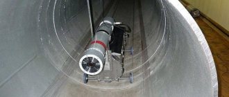
Control progress. Scheme, process.
An example of an MTD section and the progress of the control process.
1. Table for placing Control Objects (OC) into the basket 2. Cleaning bath with a cleaner 3. Rinsing bath with water with a corrosion inhibitor 4. Table / buffer in front of the MPC 5. MPC bench UNIMAG 600 AC/AC 6. Bath with a suspension according to technical specifications with mixing MPC suspension 7. Inspection table
8. Demagnetization tunnel DEMAT 300 AC+ with a 3 meter long conveyor 9. Table/buffer before cleaning from the suspension 10. Table/buffer before drying 11. Drying oven with thermostatic control for drying OK 12. Table for basket with OK after MPC 13. Buffer Waste water tank for treatment system before and after MPK
Example of a fluorescent capillary flaw detection line
The LPM 300 line consists of working positions: tables, baths, cabins and dryers.
All technological parameters and the control protocol are recorded by the line operator or an automatic control and archiving system (optional).
The parts are placed in baskets 550 x 550 x 100 mm. The internal size of the baths with technological equipment inside the bath is 650 x 650 x 600. The volume of the baths is approximately 300 liters. The baskets move along roller tracks with fixation in the center of the working positions.
Loading and unloading from individual baths is carried out by lifting and lowering platforms, i.e. elevators. Where necessary, the baths have manual lids.
| № | Stage name | Description |
| — | Table for feeding parts into motion along a roller track | |
| Ultrasonic degreasing | Immersion bath with thermostat, timer, 25 kHz 400 W generator and lifting platform onto the roller track | |
| Flushing (1) | Immersion bath with thermostat, timer, bubbling, automatic demineralized water refill and lifting platform | |
| Etching | Immersion bath with thermostat, timer, solution circulation and lifting platform | |
| Flushing (2) | Immersion bath with thermostat, timer, bubbling, automatic demineralized water refill, manual watering gun and lifting platform | |
| Drying (1) and Drying (2) | (2) Drive through a roller tunnel with convection heating system up to 130°C and a timer | |
| Cooling | Table with two sections for two baskets and cooling fans | |
| Penetration | Immersion bath with temperature sensor, timer and lifting platform | |
| Penetration Exposure | Holding on a table with a basket and a bath for the flowing penetrant | |
| Flushing (3) | Immersion bath with timer, bubbling, water supply from a closed cleaning circuit and lifting platform | |
| Emulsification | Immersion bath with emulsifier, bubbling, timer with light and sound alarm and lifting platform | |
| Flushing (4) | Immersion bath with thermostat, timer, bubbling, water inlet and outlet, lifting flush gun with pressure gauge, air gun with pressure gauge and lifting platform | |
| — | Transport table | |
| Drying (3) | Placing the basket in a chamber with a thermostat, fans, timer, light and sound alarms | |
| Developer | Room in a cabin with an exhaust hood, filter, timer, fan and system for automatic dosed vortex application of developer | |
| Developer blowing | Blowing an object with an air gun on a table with a curtain, hood, filter and roller track | |
| Inspection cabin | Inspecting objects on a turntable in a booth with curtain, UV lamp illumination, white light illumination, ventilation and roller track | |
| Flushing (6) | Immersion bath with thermostat, timer, bubbling, automatic top-up of demineralized water and lifting platform onto the roller track | |
| Table | Place the basket on a table with an air gun and a drip tray. |
Magnetization options
Most magnetization options are applied to parts of basic geometric shapes, and they get their name partly from these shapes:
- Circular magnetization creates an even field inside the element under study, with no poles appearing at the edges.
- Longitudinal, or, in other words, polar, creates a field directed along the field, with a plus at one end and a minus at the other.
- Combined - in different perpendicular directions causes the emergence of multidirectional fields.
- Rotating field magnetization is often used in industrial plants to evaluate the quality of a weld.
- Types of electric current used for magnetization:
- Constant, to form uniform induction;
- Variable - more often used for simple, low-sensitivity testing techniques;
- Pulse - its features are more similar to constant.