Magnetic field amplifier
The electromagnetic field is inextricably linked with current. Its properties are used in all electrical machines, electronics and automation devices. The purpose of magnetic cores is to transmit and amplify the magnetic field.
A magnetic field amplifier is a core surrounded by turns of coils (windings). Depending on the type of material used, certain characteristics of the MP are achieved.
There are two types of amplifiers based on their operating principle:
- amplistates – UMPs of static design;
- Transducers are a device with moving elements.
Why is a magnetic circuit needed?
To understand what a magnetic circuit is, we need to consider the structure of a simple transformer. Two induction coils are wound on cores combined into a single structure. They are the magnetic circuits (MC).
Hysteresis loop
The energized primary coil induces a magnetic field into the core, which induces magnetic flux into the secondary winding. As a result, the MF induces a current in the second coil, but with different characteristics.
Important! The cores are made of special transformer steel - ferrites. It is an alloy of iron with oxides of other metals.
Armored magnetic circuit
Transformer operating modes. part 2
In Fig. Figure 4.14 shows the dependence of the quality factor of coils with armored magnetic cores on frequency.
| To determine the total reactive drop (voltage. |
In accordance with the above recommendations, we select an armored magnetic circuit for the transformer.
| Magnetization curves of an armored magnetic core of the ShL type made of EZZO steel with a tape thickness of 0 35 mm (at a frequency of 50 Hz.| Magnetization curves of a rod magnetic core of the PL type made of EZZO steel with a tape thickness of 0 35 mm (at a frequency of 50 Hz. |
The dependence of magnetic characteristics on size is most clearly expressed in armored magnetic cores of the ShL type.
Let us consider, as an example, a PF with oscillatory circuits made using armored magnetic cores made of carbonyl iron.
Let's find how much the dimensions and weight of the transformer will change if we use a plate armored magnetic core made of E44 steel with a thickness of 0 2 mm instead of a strip one.
A rod-type core has a larger heat transfer area, however, armored magnetic cores can also be used in the designs of output transformers. The materials used for magnetic cores (stamped and strip) are electrical steels E46, E310, EZZO, as well as permalloy 45N, 50НХС and permendur. For powerful output transformers, wires with high-strength insulation made of vinyl PEVT or fiberglass PSD are used. Transformers have a protective metal casing or bracket. They are mounted similarly to power transformers.
Furnace with induction unit shown in fig. 15 - 1, has a single-phase transformer with an armored magnetic core. Transformers with core magnetic cores are also widely used.
The stability of coils with ring magnetic cores over time does not exceed the values characteristic of coils with armored magnetic cores.
Thus, the current density in the secondary winding should be taken to be 30% lower for transformers with armored magnetic cores and 15% lower for transformers with core magnetic cores.
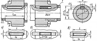
For transformers and chokes, two types of magnetic cores are used: rod and armored, shown in Fig. 5.9. When using an armored magnetic core, all the windings of the transformer are placed on one coil, which is placed on the middle rod. When using a rod magnetic conductor, two coils are placed on two rods. In low-power power and low-frequency transformers, armored cores are used, since the use of one coil simplifies the design and allows one to obtain the maximum fill factor of the magnetic circuit window with copper.
A feature of high-voltage and high-potential transformers is the predominant use of core magnetic cores, which distinguishes them from low-voltage transformers, in which armored magnetic cores are most often used.
The coupling coefficient values for various coils are given in table. 4.5. The greatest difficulties arise when obtaining large coupling coefficients between single-layer and multilayer coils, as well as when it is necessary to ensure a very small specified coupling value between coils with armored magnetic circuits.
| Armored magnetic conductor.| Rod magnetic circuit.| Toroidal magnetic circuit. |
Characteristics and principle of operation
The principle of operation of the MF is to increase the magnetic field directed to the secondary winding of the electrical device. The characterizing values of MF directly depend on the composition of the alloy used for the manufacture of cores. Ferromagnets are considered the most effective amplifiers.
Electromagnet
In order for the magnetic flux strength in the core to constantly increase, it is necessary to increase the current strength and the number of turns in the coil.
You should understand! The magnitude of the magnetic field is limited by the characteristics of the material from which the core is made.
To clearly express the characteristics of the magnetic circuit, they are displayed graphically on coordinate axes. The change in values looks like a closed curved line called a hysteresis loop.
Hysteresis loop
What is the source of the magnetic field
Hysteresis in Greek means delay. The graphical representation of the hysteresis loop reflects the degree of magnetization of a body located in an external magnetic field. Hysteresis is the dependence of magnetization vectors and magnetic field strength in any medium on the applied external MF. The state of the body at a given time is compared with its previous state. In this case, there is a lag in the body’s reaction to the influence of external MF. The physical effect is clearly manifested in ferromagnets: iron, cobalt, nickel and their alloys. The hysteresis loop provides an explanation for the existence of permanent magnets.
Hysteresis loop
Note ! Magnetic hysteresis of a ferromagnet is the lag between changes in the degree of magnetization of a body and changes in the external magnetic field. That is, the loop shows the dependence of the degree of magnetization on the sample’s history.
The magnetic permeability of a ferromagnet is a variable value; it is closely related to the induction of an external field. The magnetization curve of the core is a curved loop, at a certain degree of saturation of the ferromagnetic field. In the future, this value does not increase. If the external induction is reduced to zero, the ferromagnet will retain residual magnetization. When the direction of the external field changes, the ferromagnet is remagnetized in the opposite direction.
Use of low loss magnetic core material
For transformer magnetic cores, the choice of metal from which they are made is critical. It is therefore important that steel with good magnetic properties is used. There are many grades of steel that can be used for the magnetic core of a transformer. Each has its own impact on efficiency on a per unit weight basis. The choice of material depends on the assessment of no-load losses and the overall cost of owning the transformer. Today, almost all transformer manufacturers use steel for their magnetic cores, which provides low losses associated with the influence of magnetic hysteresis and eddy currents. To achieve these goals, cold-rolled silicon steel, with high magnetic permeability and grain orientation, is almost always used. When assembling the magnetic circuit, the plates are connected at an angle of 45°With a shift, and the plates themselves are carefully laid.
Design features
Magnetic cores are manufactured in butt and laminated versions. The designs differ in the way the cores are connected to the yokes (the part of the cores without windings).
Butt design
The MP parts are assembled separately. Windings are installed on vertical cores. Then they are fastened with a horizontal upper yoke using pins. After this, the lower yoke is mounted. This design is convenient in that by removing the studs and removing the horizontal section, you can always change the windings. The butt design is used in shunt current-limiting devices of reactors.
Laminated structures
The rods and yokes are made in the form of layered slabs. Each package consists of two or three layers of steel plates. Connections of parts are made by inserting elements into the gaps between the layers of the magnetic circuit. This method of installing MP parts is called laching. The complexity of forming the entire structure of the transformer causes the risk of poor-quality assembly of the device.
Types of magnetic cores
Magnetic cores are made of rod, armor and ring structures.
Rod type
Vertical cores of stepped cross-section form a circle with horizontal yokes. The windings are located only on the vertical elements. The entire magnetic circuit system is arranged in the form of a closed circuit.
Lamellar magnetic cores
Armor type
The cores have a rectangular cross-section. They occupy a horizontal position. The windings are also made in a rectangular shape. In order to implement such an equipment configuration, a rather complex production technology is required. Therefore, this type of MP is used only in special types of transformers.
Ring – toroidal type
Ring tape magnetic cores are used in the assembly of single-phase power transformers. MPs are made from cold-rolled electrical steel with a thickness of 0.08, 0.3 and 0.35 mm. Toroidal cores are made of ferrite or carbonyl iron. They are widely used in radio electronics.
Ring toroidal MPs
Types of magnetic cores and their use
Let's take a closer look at the features of magnetic cores designed for different devices.
For transformers, single-phase or three-phase magnetic cores are used. Among single-phase devices, rod and armor devices can be distinguished. The core magnetic circuit consists of two rods on which two coils with windings are installed. The armored magnetic circuit consists of a rod on which windings and a yoke are located. The magnetic flux splits into two parts from the rod. This type of magnetic circuit is used in low-power transformers. This is due to the fact that it is not adapted to high thermal loads. A core magnetic core, which has a larger area for cooling the winding, is better suited for power transformers.
For three-phase devices, either 3 single-phase structures are used, or a common winding with individual cells is assembled.
The most commonly used design in this case is the arrangement of the windings on a separate rod. If the production is small, then the magnetic circuit is often installed on its own from blank tapes. That is, iron strips are wound onto a finished coil of wire - a magnetic circuit.
Moreover, if tapes are used, then their thickness should be 0.2 or 0.35 mm, and if plates are used, then 0.35 or 0.5 mm. This is due to the fact that the tape must be wound very tightly, which cannot be done if the thickness of the material is too large.
For relays and starters, the design of the magnetic circuit does not fundamentally change. The only difference is that it includes 2 parts - movable and stationary. If a magnetic flux appears, then the moving part with the contact is attracted like a magnet, and if there is no magnetic flux, then it returns to its previous position. Magnetic cores operating with direct current are manufactured by casting a single piece; thin plates are not used for them. Their core is round, and the body and yoke are rectangular. The magnetic core for an electric machine is slightly different in design. This is due to the presence of a movable rotor. In this case, empty spaces are made in the magnetic circuit for the placement of wires, because inside them there are windings where current flows to ensure minimal dimensions.
Related materials:
← Previous page
Next page →
Application of transformers
When transmitting electricity over long distances, quite large losses can occur due to heating of the wires. To avoid such a negative phenomenon, transformers are repeatedly used. Initially, the voltage at the power plant is increased accordingly with a significant decrease in current. After the energy passes through the power lines, before delivering the current to the consumer, the voltage is reduced to an acceptable level (220 V) using transformers.
Since three-phase current flows in power line networks, groups of 3 single-phase transformers connected in a star or triangular circuit are used to transform it. Three-phase transformers with a single magnetic core are also used. The equipment has high efficiency. Due to this, a large amount of heat is released. Therefore, powerful transformers are placed in containers filled with special oil.
Powerful power transformer
Various electrical appliances require power supply at a certain voltage level. To do this, transformers with the required characteristics are built into their housings. High-frequency pulse transformers are used to power modern radio engineering and electronic devices.
Transformers are the basis of control and measuring devices. The point of using such devices is to safely transmit the shape of the voltage pulses of the electrical circuit under study. For example, instrument transformers are used in diesel generator systems with medium power currents (up to 1 megawatt).
Matching transformers are used when connecting devices with low resistance to electronic stages with high input or output resistance values. An example would be connecting an audio amplifier to speakers that have very low impedance.
Additional Information. The amount of energy losses in a transformer directly depends on the quality of the electrical steel core. Minimal losses due to heating, hysteresis and eddy currents occur where the cores are assembled from a large number of sections.
Transformer magnetic core
magnetic circuit
As you probably already know, all transformers are designed to convert different voltage values. And its main parts are: magnetic core and windings. Today we’ll talk about the magnetic circuit. It is a set (package) consisting of plates isolated from each other. These plates are made from special materials - ferromagnets that can be well magnetized. Basically, plates for magnetic circuits are made of electrical steel; this high-carbon steel is easy to manufacture and therefore cheap. These plates are collected in a package and form various shapes.
They can be W-shaped
T-shaped and so on.
Depending on the shape of the magnetic circuit, there are several types of it
Rod type:
Armor type:
The photo below shows a transformer made on the basis of an armor-type magnetic core. This type of magnetic core serves as a frame in the transformer and protects the windings from mechanical influences; the armored type of magnetic core also creates a good magnetic connection between the primary and secondary windings. The downside is the increased consumption of electrical steel during their manufacture.
Toroidal magnetic core type:
The toroidal type of magnetic core is the most effective, since the magnetic field created by such a magnetic core has the lowest dissipation coefficient, and an almost uniform field is created in it, which ensures the greatest efficiency. Transformers made on its basis have the highest efficiency, but due to their complex shape they are difficult to manufacture, as a result of which their price increases.
toroidal coil
There is only one type of transformers that does not use a magnetic core, these are air transformers; high-frequency current flows in such transformers, in which the magnetic core is practically not magnetized.
It should also be remembered that all plates in the magnetic circuit are insulated from each other to reduce eddy current losses. The fact is that both in the secondary winding and in the magnetic circuit itself, an EMF is induced, which is not useful and is spent only on heating the magnetic circuit itself, and consequently the windings themselves. To reduce these losses, each magnetic circuit plate is insulated from each other, thus increasing the resistance, that is, reducing the current.
There are also tape magnetic cores, which are not very often found in transformers, but are also a very successful option for making a magnetic core.
Magnetic cores are used not only in transformers, but also in other electrical machines and electrical apparatus and devices. In all electric motors and generators, both in stationary (stators, frames) and moving (rotors, armatures) parts. And also in chokes, magnetic starters, relays, etc.
The dimensions of the magnetic circuit are determined by the voltage and power of the transformer being manufactured, as well as depending on its type.
Ferrite grades
Ferrites according to their composition are divided into two groups: manganese-zinc and nickel-zinc. Manganese-zinc ferrites are designated by the letters NM, respectively, nickel-zinc substances are marked by the letters - NN. The number before the letter designation of ferrite means the value of the initial magnetic permeability in units of µinit. This indicator is given with an adjustment to the nominal value. For example, ferrite grade 4000NM has a magnetic permeability with a deviation ranging from – 800 to + 500 µinit.
Magnetic cores are of exceptional importance in the formation of devices such as transformers and other electrical devices. The initial technical characteristics of the devices largely depend on their qualitative composition.