A weld is a trace formed after welding and connecting parts into an integral structure - a welded joint. Although welds and seams belong to the same manufacturing process, these concepts should not be confused.
The welding seam is subject to specific requirements regulated by regulatory documents. One of such documents is GOST 2601 – 84 “Welding of metals. Terms and definitions of basic concepts."
In this review, the main subject of consideration is the weld formed by manual arc welding (MMA), its classification, technology and common welding defects.
Manual arc welding
Manual arc welding is welding with a metal electrode coated with a special coating, to which welding current is supplied to form and maintain an electric arc. The arc is ignited when the end of the electrode briefly touches the workpiece being welded.
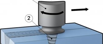
Manual arc welding process diagram:
| 1) Crystallized weld metal. | |
| 2) Hardened slag. | |
| 3) Weld pool. | |
| 4) Gas atmosphere of the arc. | |
| 5) Electrode rod. | |
| 6) Electrode coating. | |
| 7) Drops of molten electrode metal. | |
| 8) Depth of penetration. | |
| 9) Product to be welded. | |
| 10) Welding direction. |
Let us consider in more detail all the processes occurring during the welding process:
- Under the action of an electric arc, the metal rod of the electrode and the metal of the welded product melts. The electrode metal in the form of separate drops covered with slag passes into the weld pool, where it mixes with the base metal, and the molten slag floats to the surface.
- Slag, covering drops of molten electrode metal and the surface of the weld pool, prevents their interaction with air, and also helps clean the molten metal from impurities.
- When the electrode coating melts, a gas atmosphere is formed around the arc and above the weld pool, displacing air from the welding zone to prevent its interaction with the molten metal.
- The final step is that the metal of the weld pool crystallizes and a seam is formed.
How are the properties of a welded joint determined?
Methods for determining the mechanical properties of a welded joint as a whole and its sections, as well as the properties of the deposited material, are regulated by the provisions of GOST 6996-66. Tests are carried out to determine the quality and development of technology in large-scale and mass production.
Interesting: Features of inspection of welded joints
According to GOST, tests are carried out to determine quality in the following ways:
- Static - the breaking load is gradually increased on tensile testing machines, the tests are extended over time so that the stress is constant.
- Dynamic – tested on special pendulum impact drivers. The load acts in a short period of time, increasing to a maximum almost instantly.
- Fatigue - on special machines the sample is repeatedly loaded with a load of different sign and value. The number of cycles is up to several million times.
- The hardness of the weld areas and adjacent metal is measured using machines that measure hardness using the Rockwell, Brinnell, and Weckler method.
To determine quality during acceptance, non-destructive methods are used:
Visual and measuring control - checking by external inspection for the presence of welding defects in the control zone.
Ultrasonic method – ultrasonic frequency waves are emitted in the control zone. Reflecting from the back side of the metal, the waves return and are received by the sensor. Wave reflection does not occur at the defect site and this is visible on the indicator.
Capillary method - based on the ability of certain liquids (penetrants) to penetrate microcracks. Liquids contain coloring pigments and the presence of defects is determined by the appearance of paint on the surface.
Pneumatic method - air is supplied under pressure, and on the other side a soap solution. The presence of fistulas and lack of penetration is determined by the formation of bubbles.
Hydraulic - pour in liquid and hold until the liquid fills the microcracks. Then the product is taken out and tapped with a hammer. Defects are determined by the presence of leaks.
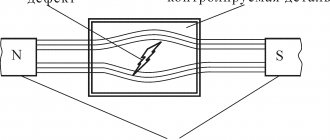
For steel parts, the magnetic method is used - the product is magnetized with direct current and metal powder is scattered on top. The powder, under the influence of a magnetic field, lines up along the magnetic lines. If there are defects, the powder reveals them by distorting the pattern.
Welded joint, seam shape and image in the drawing
Having understood the process of manual arc welding, during which a seam is formed, let’s move on to considering the main zones of the weld and its shapes.
The welded joint includes four zones of metal:
| 1 ) The weld zone is an alloy formed by the molten base and weld metals. | |
| 2 ) In the fusion zone , where the heating is below the melting temperature, there are partially melted metal grains at the boundary of the base metal and the weld metal. The metal grains here are separated by liquid layers associated with the liquid metal of the weld pool. | |
| 3 ) The heat-affected zone is a section of the base metal that has not undergone melting. The structure and properties of this zone change as a result of heating during welding. | |
| 4 ) Part of the base metal adjacent to the heat-affected zone. |
There are front and back sides of the seam. The front side in a one-sided seam is taken to be the one from which welding is performed. In a double-sided weld with an asymmetrical bevel - the side from which the main seam is welded. In a double-sided seam with a symmetrical bevel - either side.
Weld sides
According to the shape of the outer surface, welds are:
| 1 — 2 — 3 - convex seam. When it cools, shrinkage (indicated by a dotted line) occurs calmly. The dotted line of the weld is shorter than the original one, so no tensile stress occurs in the weld. | |
| 1 — 4 — 3 - concave seam. The shrinkage of the seam proceeds with the lengthening of the contour curve, so local rupture and crack may occur. |
Basic geometric parameters of a butt weld according to GOST 2601 – 84:
| S is the thickness of the metal being welded. | |
| e is the width of the weld. | |
| g - convexity of the butt weld - the greatest height (depth) between the surface of the weld and the level of the surface of the welded parts. | |
| h - penetration depth (depth of penetration) - the greatest depth of melting of the base metal. | |
| t is the thickness of the seam (g + h). | |
| b - gap. |
Basic geometric parameters of fillet weld according to GOST 2601 – 84:
| K - fillet weld leg - the shortest distance from the surface of one of the parts being welded to the boundary of the fillet weld on the surface of the second part being welded. | |
| g - convexity of the seam. | |
| Hp - design height of a fillet weld - the length of a perpendicular line drawn from the point of greatest penetration at the junction of the welded parts to the hypotenuse of the largest right-angled triangle inscribed in the outer part of the fillet weld. | |
| a is the fillet weld thickness (g + p). |
Visible welds in the drawing are depicted by the main line, and invisible ones - by dashed lines:
Seam designation in the drawing
How are welds and connections designated?
Classification and designation of welds is made using special icons, lines and callouts. They are placed on the assembly drawing and on the structure itself. The classification of welded joints and seams is indicated, according to the regulatory document, using special lines, which can be solid or dashed. Continuous welds indicate visible welds, dashed welds indicate invisible ones.
Seam symbols are placed on the shelf from the leader (if the seam is located on the front part). Or, conversely, under the shelf if the seam is placed on the reverse side. Using icons, the classification of welds, their discontinuity, and the placement of segments for welding are indicated.
Next to the main icons there are additional ones. They contain supporting information:
- about removing the weld reinforcement;
- about surface treatment for a smooth transition to the base metal and to prevent sagging and unevenness;
- about the line along which the seam is made (is it closed).
For identical designs and products of the same GOST, standard symbols and technical requirements are provided. If the design has identical seams, then it is better to give them serial numbers and divide them into groups, which are also assigned numbers for convenience. All information about the number of groups and seams must be indicated in the regulatory document.
Classification of welds
There are different types of welds and seams. The developed classification takes into account the technological features of the seams, their spatial position, dimensions and other factors. This paragraph discusses in detail all types of welds and structural connections.
According to the location of the welded elements
Depending on the relative position of the welded elements, the following types of welded joints are distinguished:
| Butt joints (seam types C1 - C48) . With this processing method, the parts are located in the same plane. In this case, welding can be carried out both on weight and on a lining. The butt weld is suitable for joining pipes and metal sheets. The resulting connections have the lowest stress concentration and ensure equal strength of the connection with the base material. |
| Lap joints (types of welds H1 - H2) are made with parallel arrangement of parts in space. In this case, one part partially overlaps another. The overlap connection is applicable when welding metal sheets with a thickness of no more than 12 mm. If during operation of the unit, fracture loads are possible, then it is better to avoid using this connection method. |
| With T-joints (types of seams T1 - T9) , made with fillet welds, the end of one part is located perpendicular to the main surface of the second part. Such a connection is widely in demand when constructing load-bearing structures, since it is considered the most durable - capable of withstanding increased loads. |
| Corner joints (weld types U1 - U10) are made by placing parts at an angle (usually at a right angle) and then welding them at the junction of the edges. According to the manufacturing technology, such connections can be one-sided or two-sided, and the welds used at their base are fillet welds. Corner joints are most often used when connecting parts of various containers and reservoirs. |
| With end connections, the workpieces are placed parallel, one on top of the other, and welded together at the ends. In this way, parts of any thickness can be connected with minimal deformation. |
| Fused welds are a special type that is used in T-joints, lap joints and is limited to parts up to 10 mm thick. Such seams are made by completely melting the top sheet and partially melting the bottom sheet of the workpiece. A type of penetration welds are cork penetration welds. They are formed as a result of melting of the upper thinner sheet. Such electric rivets can be installed either without a hole in the sheet being welded or along a hole. |
Welding seams by length
The length of the seams can be continuous or intermittent:
| 1) Continuous one-sided seam. | |
| 2) Intermittent one-sided seam. | |
| 3) Continuous double-sided seams. | |
| 4) Double-sided chain stitches. | |
| 5) Double-sided checkerboard seams. |
Intermittent welds are suitable for non-stressed (and/or leaking) joints and can be arranged in a chain or staggered pattern. The length of the connected sections ( l ) is usually 50 - 150 mm. The gap between the seams ( t ), called the step, is usually made 1.5 - 2.5 times the length of the welding zone l .
Welds by number of layers
Depending on the number of layers, welding can be single-layer or multi-layer, and based on the number of passes – single-pass or multi-pass. It is advisable to use a multilayer weld when processing thick metal. Also, using the multi-layer method on thinner workpieces, it is possible to reduce the heat-affected zone.
Structure and terminology of a multilayer weld:
| Weld layer - weld metal consisting of one, two or more beads that are placed at the same level of the cross-section of the weld. | |
| Pass - a single movement of a heat source in one direction during welding or surfacing. | |
| Bead is a portion of the weld metal that has been deposited in one pass. |
When performing a multi-pass weld, it should be taken into account that each new layer should be applied quickly, before the previous one has cooled down (the time spent on removing slag must also be taken into account).
The positive effect of multi-pass technology includes the fact that when a subsequent seam is applied, annealing occurs in the previous one. Annealing is a type of heat treatment that involves heating to a certain temperature, holding for a certain time at this temperature and then, usually slowly, cooling to room temperature.
Seams according to position in space
According to their position in space, seams are divided into:
| a) Lower . This position of the workpieces is the most convenient for the welder. | |
| b) Horizontal . This arrangement of the seam line, as in all other cases, leads to metal dripping during operation. You can combat this by increasing the speed of movement of the electrode, or regularly interrupting the arc, allowing the metal to cool. | |
| c) Vertical . In this case, there is also the problem of molten metal (drops) draining. And if welding is carried out from top to bottom, then these droplets will begin to quickly solidify, forming a kind of barrier. Therefore, welding with the vertical method should be carried out from the bottom up. | |
| d ) Ceiling (top) . Such seams require a certain skill from the welder, since during the work he will have to take an unnatural posture. Welding of the ceiling joint is carried out in short arc mode with electrodes no thicker than 4 mm. The width of the seam should be less than the thickness of the electrode. Welding should be done in the “toward” direction. |
Weld seams by appearance
Based on the appearance of the outer surface, welds are divided into convex (reinforced), normal and concave.
Shape of butt welds:
| a ) Convex weld | |
| b ) Normal seam | |
| c ) Concave seam |
Typically, when manual welding, convex (reinforced) seams are used, which work better under static (constant) loads. However, when choosing a more reliable connection, you should understand that they are uneconomical in terms of electrode and energy consumption.
If the welded product is expected to be subject to dynamic loads during operation, then when joining workpieces it is better to use a normal (flat) or concave seam. The advantage of this approach is that there is no large difference between the surfaces of the welded products and the seam.
Possible flaws
Defects during welding can occur due to excessive current and arc voltage. This may also be the result of improper manipulation of the electrodes. Classification of weld defects according to their location:
- Internal. To identify them, a technique is used that consists of control: not destroying the structure, destroying it completely or partially.
- External. They are easily identified during external examination.
Due to a violation of the welding regime caused by a lack of necessary experience, insufficient preparatory work, or incorrect measurements, defects are divided into:
- Lack of penetration. Manifests itself in the local absence of fusion between the connected elements. The defect leads to an increase in stress concentration and a decrease in the weld cross-section. A design with such a flaw is characterized by reduced strength and reliability. Lack of penetration can be caused by either insufficient current or fast welding.
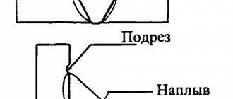
- Undercut The defect consists of a local decrease in the thickness of the base metal. This problem is observed near the boundaries of welds.
- Burnout. The flaw looks like a cavity in the weld. It occurs due to leakage of molten metal from the weld pool. A burn-through is an unacceptable defect and needs to be corrected urgently.
- Unsealed crater or depression. Occurs due to arc breaks while approaching the end of the seam.
- Influx. The defect manifests itself in the flow of weld metal onto the base metal without fusion.
Read also: How to clean a machine with citric acid
The causes of defects can be very different, but they are equally capable of reducing adhesive strength, operational reliability, accuracy and spoiling the appearance of the product.
Position and movement of the electrode during welding
The inclination of the electrode during the welding process affects the rate of heating of the metal. Therefore, the choice of the optimal angle depends on the types of welded joints and the types of seams used.
The next important nuance when welding is the way in which the electrode moves in the process of creating a weld. The trajectory of movement is selected depending on the thickness of the workpieces and the types of welding joints.
The following schematic image clearly illustrates the permissible trajectories of electrode movement when creating vertical, horizontal and ceiling seams:
Transverse oscillatory movements of the electrode during welding provide good heating of the root of the weld and its edges, making the connection more durable. Also, the amplitude of vibration allows you to obtain a seam of a given size. There are various looped figures that the electrode draws when welding - “ladder”, “triangle”, “Christmas tree”, “crescent”, “loop”. The choice depends on the types of welding joints, as indicated in the diagram above.
Electrode position when welding:
| Angle forward - suitable for horizontal, vertical, ceiling seams, welding fixed pipe joints. The welding process will be interfered with by liquid slag, which is always in front. The welding arc may go out or begin to “wander.” If missing areas appear, the quality of the seam may be reduced. | |
| At right angles - for welding in hard-to-reach places. This position allows you to control the liquid slag and ensure that it moves with the weld pool. | |
| Corner and butt joints are welded at an angle backwards | |
| Arc breakage at the end of welding . At the end of the seam, you cannot break the arc immediately. The electrode must be moved to the upper edge of the weld pool (position 1 - 2) and then quickly moved away from the crater to position 3. | |
| Filling the crater (first method) . The arc must be interrupted at the end of the weld (1) and then re-ignited (2) to form the required height. | |
| Crater filling (second method) . From position 1, without breaking the arc, you need to move the electrode by 10 - 15 mm to position 2, and then to position 3, after which the arc can be broken. |
In order for the arc to strike, the electrode must be held perpendicular. Then you need to perform a slight tilt. The welding seam will be of better quality if welding is carried out with a short arc.
Overlap welding
The principle of this type of connection is the double-sided welding of products whose thickness is no more than 1 cm. This welding is used in cases where it is necessary to prevent moisture from entering the gap between steel sheets. As a result of this work, two seams are formed. This type of welded joint is considered long-lasting and is not economical, since more materials are required for the job.
Weld defects
The causes of defects may be:
- Poor quality material or malfunction of the equipment used.
- Errors during the production process, insufficient qualifications of the welder.
- Violation of the technological process. Selecting electrodes of the wrong size, turning on a mode inappropriate for the type of welding on the equipment, voltage fluctuations in the electrical network, inappropriate speed of the process.
- When welding outdoors, bad weather conditions may adversely affect you.
Types of defects, depending on the location of occurrence:
- External defects are clearly visible upon visual inspection. These include sagging, cracks, bulges and depressions, undercuts, fistulas. This also includes the presence in the weld of sections that differ in width, and in corner joints - different sizes of legs.
- Internal (lack of penetration, pores, cracks). The reasons for the occurrence are insufficient quality of the base material, violation of welding technology.
- Through pores (pores running through the entire thickness of the seam) can also be detected by visual inspection.
Types of weld defects and causes of formation:
| Cause of defect | Scheme |
| Craters in the weld seam can be formed due to arc breakage or improper execution of the final section of the seam. | |
| Pores can occur due to: rapid cooling of the seam; contamination of edges with oil (rust); undried electrodes; high speed welding. | |
| Slag inclusions in the weld are a consequence of: dirt on the edges; low welding current; high welding speed. | |
| Non-fusion may occur due to: poor edge cleaning; long arc length; insufficient welding current; high welding speed. | |
| The reasons for the influx are: high welding current; incorrect tilt of the electrode; excessively long arc. | |
| Fistulas in the weld seam occur due to: low ductility of the weld metal; formation of hardening structures; stress from uneven heating. | |
| The reasons for the formation of undercuts are: high welding current; long arc; displacement of the electrode towards the vertical wall (when welding fillet welds). | |
| Lack of penetration is formed due to: a small bevel angle of the vertical edges; small gap between edges; edge contamination; insufficient welding current; high speed welding. | |
| Burn-through of the weld seam is a consequence of: high current at low welding speed; large gap between edges; poor compression of the flux pad or copper lining under the seam being welded. | |
| An uneven shape of the seam is formed when: unstable welding mode; inaccurate direction of the electrode. | |
| Cracks in the weld are formed due to: sudden cooling; high voltage (physical impact) in rigidly fixed structures; high sulfur or phosphorus content. | |
| Overheating (burnout) of the metal occurs due to: excessive heating of the heat-affected zone; incorrectly selected thermal power; excessive flame power or welding current. |
GOST 5264-80 (Manual arc welding. Welded joints), GOST 30242-97 (Defects in joints during fusion welding of metals. Classification, designation and definitions) clearly regulate the requirements for welds, determine which defects in which welds are permissible.
Requirements for welds
Requirements for seams depend on operating conditions, types of load, metal properties, welding technology, etc. GOST standards have been developed to classify them according to specific conditions. For example, the requirements for manual welding joints are given in GOST 5264-80.
Common to all seams, regardless of conditions, include:
- strength;
- reliability;
- durability;
- resistance to corrosion and aggressive substances.
In order for the seam to be of high quality, it is necessary to follow the technology of metal preparation and welding.
You can learn about the length and thickness of seams depending on the design features and grade of metal, quality control methods, etc. from thematic SNiPs, which are easy to find in the public domain. The information obtained can be used as a cheat sheet when performing complex work.
Welding seams in various spatial positions
Selecting manual arc welding mode
The choice of manual arc welding mode comes down to the following:
1. It is necessary, first of all, to select the diameter of the electrode depending on the thickness of the metal being welded. There are tables for this that are difficult to remember, so in practice they do this:
— if the metal thickness is up to 4 mm, the diameter of the electrode is equal to the thickness;
— if the metal thickness is more than 4 mm, the electrode diameter is 4–6 mm.
The choice of diameter is also influenced by the spatial position of the seam during welding. So, for example, when welding vertical seams from top to bottom and ceilings, it is not recommended to use a diameter of more than 4 mm, since with a larger diameter the current strength is greater, which increases the volume of the weld pool and the flow of molten metal out of it. When welding thick metal, with beveled edges, for a fundamental seam, in order to avoid lack of penetration, use electrodes with a diameter of no more than 3 mm, and when applying subsequent layers, you can use electrodes of a larger diameter.
2. With the selected diameter, it is necessary to select the strength of the welding current. To do this, you can use the general formula I = K × D, where D is the diameter of the electrode; K – coefficient equal to (40 – 60) A/mm; A coefficient closer to 40 is selected when welding alloy steels, since the more alloyed the electrode rod, the greater its resistance and the greater the likelihood of overheating. A coefficient closer to 60 is selected when welding higher-carbon steels, in order to more quickly introduce heat and reduce the hardening width of the thermally affected zone. When welding low-carbon structural steels, the strength of the welding current can be approximately determined using a factor of 50, i.e. I = 50 × D.
To more accurately determine the strength of the welding current when welding low-carbon structural steels, Academician Khrenov’s formula I = (20 + 6xD) × D is used.
This calculation is made with the seam in the lower position. When welding seams in a vertical and horizontal position, the welding current is reduced by 5 - 10%, and in the ceiling by 10 - 15%, in order to reduce the volume of the weld pool and the flow of molten metal from it.
When welding metal with a thickness of more than 1.5 De, the current can be increased by 10 - 15% for greater productivity without fear of burn-through.
3. The arc voltage can be determined using the already known formula Ud = a + B × Ld, where coefficients a = 10 V; b = 2 B/mm, and Ld is the arc length. When making calculations, it should be assumed that Ld = De, since in this case the arc is considered short and should be used when welding.
4. The type and polarity of the welding current is selected depending on the type of electrode coating. Electrodes with acidic, rutile and cellulose coating allow welding with both alternating and direct current of any polarity. Electrodes with the main type of coating burn steadily only at a direct current of reverse polarity and require its use.
5. The optimal welding speed can be determined using the formula
V = where Kn is the electrode deposition coefficient, selected from the tables;
I – welding current strength;
j – steel density equal to 7.85 g/cubic. cm;
F – cross-sectional area of the seam:
— for fillet welds F = ½ K × KK – leg;
— for butt welds F = 0.7 S × SS – metal thickness;
In practice, the choice of mode comes down to the following. The diameter of the electrode should be selected in accordance with the thickness of the metal, up to 4 mm in thickness - equal to the thickness, and for greater thickness - 4-6 mm.
The current strength is judged by the following criteria:
a) according to the degree of convexity and stability of the arc:
- if the seams are convex, the penetration is shallow, the arc is unstable when its length changes - the welding current is low;
- if the seams are made with a concave surface, undercuts are formed, the arc pressure on the molten metal is increased - the current strength is high;
b) by the sound and tone with which the arc burns. With the correct current strength, the sound produced by the arc is one tone.
The welder will influence the change in arc voltage only if his arc length changes significantly. And this is one of the skills that determine the qualifications of a welder - the ability to maintain a constant arc length.
The choice of the type and polarity of the current depends on the type of electrode coating, the thickness of the metal, the heat capacity of the metal or alloy being welded and other factors.
Choosing the optimal welding speed for a given metal thickness (electrode diameter and other factors) is also one of the skills that determines the welder’s qualifications.
A correctly selected welding mode will largely determine the quality of the seam, its mechanical properties and productivity.
Welding mode elements.
Their influence on the shape and size of the seam
The welding mode is understood as a set of factors that ensure stable progress of the welding process and obtain a seam of a given size and shape.
These factors are elements of the welding mode and are divided into two groups.
I. BASIC ELEMENTS OF THE REGIME. This is precisely what ensures the stability of the arc, the specified depth of penetration (Npr) and the width of the seam (B).
These include:
1. Electrode diameter
—De
2. Welding current strength
—Isv
3. Arc voltage
— Ud
4. Type and polarity of welding current
5. Welding speed
—Vsv
These mode elements are basic for all arc welding methods, be it manual arc, semi-automatic or automatic.
II. ADDITIONAL MODE ELEMENTS, which have some influence on Npr and B, but have less influence on the stability of the arc. There are quite a lot of them and they include:
1.Departure
electrode is the distance from the current supply point to the end of the electrode. When welding with a consumable metal electrode, the stickout will decrease, and when welding with a non-consumable metal electrode, carbon or tungsten, it will remain constant.
2.Electrode tilt
when welding, the smaller it is from the vertical, the smaller the Npr will be. Maximum penetration will be observed at an angle of 10 - 15 degrees from the vertical. Welding with an inclined electrode is possible with a “forward angle” and a “backward angle”, and when welding with a “backward angle”, greater penetration is observed.
3.Seam slope
, since the seams can be inclined.
4.Initial
, before welding,
metal temperature
.
5.Slag-forming properties of the coating
electrode, etc.
Let us consider how a change in one or another mode element affects the penetration depth Hpr and the weld width B, provided that only the mode element in question changes. The remaining elements remain constant at this time.
The influence of the main elements of the regime:
1. As the diameter of the electrode De increases, the current density in it decreases, which causes a decrease in the depth of penetration Hpr and an increase in the width of the seam B. On the contrary, a decrease in diameter leads to an increase in the depth of penetration (the current density increases) and a decrease in the width of the seam.
2. As the welding current increases, the penetration depth increases, but the current has no practical effect on the width of the weld. As the current decreases, the penetration depth decreases, but again the current does not affect the width of the seam.
3. An increase in arc voltage causes an increase in the width of the seam, but it has virtually no effect on the penetration depth. Reducing the voltage only reduces the width of the seam.
4. Maximum penetration is observed when welding with direct current of direct polarity. Reversing the polarity reduces the penetration depth by 40 - 50%. When welding with alternating current, the penetration depth is 20 - 30% less than with reverse polarity.
5. -At low welding speeds, up to 1 m/h, the penetration depth is small. This is explained by the fact that under the influence of arc pressure, a layer of molten metal is formed at the bottom of the weld pool, preventing further penetration. The seams are wide, with shallow penetration.
-At optimal welding speeds, from 1.5 to 25 m/h, and the welding speed is set by the welder himself, depending on the thickness of the metals, the diameter of the electrode and other factors - the penetration depth is maximum. Due to the higher speed of movement, the liquid layer of the bottom of the weld pool is removed by arc pressure, which contributes to greater penetration. Choosing the optimal speed is one of the skills that determines the qualifications of a welder.
With a further increase in the welding speed, more than 25 m/h, the penetration depth will decrease, since less and less heat will be introduced, and at a speed of about 100 m/h, non-fusion of the edges occurs, although the welding process will proceed steadily.
Impact of additional mode elements:
1. When welding with a consumable metal electrode, the stickout decreases, that is, the length of the rod, and at the same time its electrical resistance decreases. According to Ohm's law, this causes an increase in current strength and an increase in the depth of penetration. Moreover, the width of the seam practically does not change.
2. To obtain maximum penetration and high productivity, welding is carried out with an inclined electrode, deflecting it from the vertical at an angle of 10-15 degrees. In this case, welding “forward angle” and “backward angle” is possible. When welding “backwards”, the depth of penetration will be somewhat greater, since the pressure of the arc will force the molten metal onto the forming seam. By changing the angle of inclination from the vertical, you can slightly change the depth of penetration, which the welder must skillfully use.
3. Welding of inclined seams is possible on the “descent” and “ascent”. When welding “uphill”, slightly greater penetration is observed due to the removal of liquids from the layer of the bottom of the weld pool not only by arc pressure, but by gravity.
4. When welding steels of insufficient weldability, preheating is used. Metal temperature up to 200 degrees does not affect the penetration depth and width of the seam. An increase in the initial temperature causes an increase in both the depth of penetration and the width of the seam.
5. Electrodes with the main type of coating are more prone to “long” slags, which are more refractory and harden more slowly. This promotes delayed crystallization of the weld pool, wider and smoother seams.
Manual arc welding technique
1) In order to start welding, it is necessary to excite the arc in one of the following ways:
- “strike” or “match”, when the electrode is passed with its end along the surface of the metal;
- “tapping”, when the electrode is tapped on the surface of the metal;
At this time, the end of the electrode, due to which the circuit is closed, is heated for subsequent thermionic emission and ionization when the arc is excited.
2) After exciting the arc, it is necessary to establish its certain length and maintain it as constant as possible, since this is one of the skills that determine the qualifications of the welder. In length, the arc can be short or long. An arc is considered short up to the diameter used when welding the electrode. It is advisable from the beginning of practical training to acquire the skill of maintaining an arc length of 2-3 mm. The arc is considered longer than the diameter of the electrode used.
3) At the same time, you need to install the electrode obliquely, at an angle of 10-15 degrees from the vertical for maximum penetration, and begin to move it in the welding direction “forward angle” or “backward angle.” In this case, the seam will be in the form of a roller or cord laid in the edges.
4) There are narrow and wide rollers. A narrow bead is considered to be up to 1.5 times the diameter of the electrode used for welding. When applying it, the welder makes two movements:
— progressively downward, as the electrode melts and the rate of its melting;
— progressively in the direction of welding.
A bead with a width of 2 to 4 times the diameter of the electrode used for welding is considered widened. It is not recommended to use a larger width, since it is necessary that the weld pool be in a molten state at the width of the seam, otherwise the surface of the seam will not be smooth and even. When applying a widened roller, a third is added to the previous two movements - oscillating with the end of the electrode, of the amplitude required by the width of the seam.
The types of oscillatory movements are very diverse. The most widely used include:
“herringbone”: “crescent forward”; "half a month ago"; “spiral” - they are used for
V-shaped bevel of edges when the metal thickness is up to 20 mm. On the edges, when changing the direction of movement, you should delay, and the root of the seam passes more quickly.
"one loop"; "two loops"; “yarn over” - with thicker metal with beveled edges, because when making loops, you have to linger more on the edges, melting them.
"triangle"; “double spiral” - can be used with a thickness of more than 4 mm without bevelling the edges, when the heat is concentrated in the middle of the edges.
“overlap in one direction” - used when welding parts of different thicknesses. The yarn over is made to a greater thickness for greater penetration.
The greater the number of oscillatory movements a welder has and is able to use them in various situations, the higher his qualifications.
Welding seams in various spatial positions
In order to reduce the number of difficulties associated with the flow of straightened metal from the weld pool, it is advisable to place the joints so that the seams are in the lower position. But it is not always possible to provide it. And even in the lower position, when welding fillet welds, when one of the edges is located vertically and the other horizontally, difficulty arises, since metal flows from the vertical edge to the horizontal one. In this case, an unevenness of the leg is formed, smaller on the horizontal, larger on the vertical. Undercuts often form on the vertical edge, and sagging on the horizontal edge. To avoid this, it is better to weld in the “boat” position. But it is not always possible to ensure this position and you have to weld when one of the edges is located vertically and the other horizontally. The following welding technique is recommended.
- if the fillet weld leg is up to 8 mm, it can be done in one pass using loop-like oscillatory movements. In this case, the arc should be initiated on the horizontal edge at point A (see supporting summary), otherwise sagging and slag in the weld are possible. The electrode should be positioned at an angle of 45 degrees to the parts and, while making loop-like movements, change it to melt the edges.
- if the fillet weld leg is more than 8 mm, it is recommended to use multi-pass seams, applying layers after beating the slag on top of each other from bottom to top, achieving the required leg size.
When welding vertical seams, molten metal also flows out of the weld pool under the influence of gravity. In order to reduce
— the welding current must be reduced by 5-10% compared to the lower position, and the electrode diameter must be no more than 4 mm. This will reduce the volume of the weld pool and the molten metal will quickly turn into a solid state.
— weld with a short arc, keeping the drop of molten metal from flowing down with a “visor” at the end of the electrode.
Welding of vertical seams is possible in two directions: from bottom to top and from top to bottom.
Bottom-up welding is a simpler technique, since the seam formed at the bottom creates an obstacle to the flow of molten metal and experienced welders can use an electrode diameter of up to 5 mm.
Bottom-up welding is more productive, but more difficult in terms of technique, since the metal is supported from dripping only by the “visor” of the electrode
The electrode, in both options, is first positioned vertically to the edges to obtain greater penetration, and then tilted at an angle of 15 degrees, supporting the drop from flowing down and moved somewhat to the side, allowing the weld pool to turn into a solid state.
When welding horizontal seams, you should use the same recommendations as when welding vertical seams:
— reduce the welding current by 5-10%;
— choose an electrode diameter of no more than 4 mm;
— welding is carried out with a short arc;
- and in addition, bevel the edge only at the top part, and use the bottom unbeveled edge to prevent runoff.
With a metal thickness of up to 8 mm, the seam can be made in one pass using oscillatory movements in the form of a spiral. When welding thicker metal, it is recommended to use multi-pass welds, stacking layers on top of each other from bottom to top.
When welding ceiling seams, the molten metal flows out of the weld pool even more intensely, so you should work from above with a very short arc, resting the “visor” on the edges. The welding current should be reduced by 10-15 mm compared to the lower position and use an electrode diameter of 3 mm, and for experienced welders 4 mm. Welding seams in the ceiling position should be used only in cases where no other spatial position is possible, since the slags and gases that form the electrode coating during melting move upward and defects (slags and pores) are formed at the root of the seam, reducing the mechanical properties of the joint.
To weld seams in various spatial positions, electrodes with thick and especially thick coatings should be used, which form a “visor” when the arc burns, preventing a short circuit between the rod and the metal and with which the metal is supported from dripping. Welding seams in different positions should be carried out continuously without breaking the arc. It is not recommended to use periodic short circuits due to lack of penetration and slagging.
Distance between electrode and workpiece
An important parameter is the distance at which the electrode is located, as this will affect the quality of the resulting seam, its size and shape, as well as roughness.
An electric arc can be:
The ideal welding arc length is 2-3 mm.
It is recommended to work with the electrode at a very short distance for welding root seams of thick workpieces . In this case, there is no need to carry out transverse oscillatory movements. The average or maximum current strength is set.
The arc is short if the distance to the welded area is half the diameter of the electrode used . When working at such a distance, the depth of penetration of the workpieces increases, and the width of the seam decreases. A short arc is actively used for vertical welding.
The length of the average arc is equal to the thickness of the electrode used . In this case, the stress increases and the seam expands significantly.