08/29/2019 Author: VT-METALL
Issues discussed in the material:
- What is the technology of automatic welding of metal structures
- What is the technology of semi-automatic welding of metal structures
- What are the features of welding aluminum metal structures
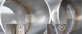
- What defects are possible when welding metal structures?
For a long time, metal structures have been connected to each other by welding. This technology is used not only by amateurs at home, but also by professionals on an industrial scale. Welding techniques are constantly being improved, so at present the result shown by the technology of welding metal structures (regardless of their dimensions) is much higher than a couple of decades ago.
Welding requirements
There is a classification of welded structures and, depending on this, different requirements are placed on them. The general definition from all the variety is that these are structures made by welding. However, it is more convenient to divide it into different types:
- according to their intended purpose - aviation, ship, carriage, construction, etc.;
- according to the thickness of the elements being connected - thick-walled and thin-walled;
- according to the method by which the blanks are produced: sheet, profile, stamped, cast;
- by materials: steel, titanium, aluminized and other metals.
Each of these options has its own characteristics when connecting elements by welding. These recommendations are usually indicated on the drawings and in the technological map. Welded metal structures after completion of their connection must have strength and reliability. Such requirements impose great responsibility on the welder to comply with certain requirements when carrying out this difficult process.
Particularly great demands are made when welding critical metal structures occurs. The quality of their implementation will determine how great the possibility of destruction of the entire object is, which is unacceptable. Only highly qualified welders have the right to perform such work. The result of welding of such structures must be subjected to control.
The characteristics that welded metal structures used in construction must have are set out in GOST 27772. Also, the regulatory document SNIP II 23-81 can be classified as guidance documentation. The requirements set out in these documents relate primarily to the activities of professional welders, but when deciding to carry out such work yourself, it would be a good idea to familiarize yourself with them.
When manual welding, one should be guided by the requirements of GOST 5264-80, and if it is carried out in shielding gas, then GOST 14771-76. Much attention in the existing regulatory documentation is paid to preparing the edges of the parts to be joined before starting welding, which guarantees the creation of a high-quality connection.
Welded structures must have the lowest possible shrinkage stresses, as well as minimal deformations. This can ensure welding of structures while maintaining the stability of the selected mode. The spread of current and voltage values should not exceed 5%. To meet these requirements, drawings of welded structures are made, and a special map describes the technological process of welding metal structures.
Drawings of metal structures
The manufacture of welded structures should be carried out in accordance with the requirements specified in the drawings on them. Drawings for welded metal structures have their own characteristics, so you need to be able to not only draw them up correctly, but also read them. To do this, it is necessary to study the symbols used on these design documents.
At the initial stage of development, general drawings are created, united by the name “KM”, which stands for metal structures. They indicate welding of structures in general form.
At the final stage, a set of “KMD” drawings is produced - detailed metal structures, which include all the drawings of each part involved in this type of connection. “KM” is the basis on which the drawings included in the “KMD” kit are developed. Providing “KM” is necessary in order to obtain permission to build a future facility. They will be used for future welding of building structures.
When drawing up drawings, you should be guided by the standards set out in GOST 2.410-68, which clearly outlines the rules by which drawings for metal structures should be made. High-quality assembly and welding of metal structures directly depend on competent drawing up of drawings. The general view gives an idea of what the structure should look like after welding.
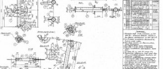
The drawings contain technical data in special tables that serve as a guide for proper welding.
You need to start reading the drawings in a certain order. First, you should familiarize yourself with the first drawing of the kit to get a general idea of the work ahead. Then you need to familiarize yourself with the “list of elements”. For each part, called an element mark, it contains information about its section with a small sketch that can show individual dimensions, for example, a step.
The “Pos” column indicates the position number of the part in the drawing. Nearby in the “Composition” column there is an abbreviated designation of the profile that the section of the part has according to the rules of their symbolic designation in accordance with the requirements of GOST 2.420. Next come the columns that indicate the effort and grade of steel.
This app is required. The special significance of the statement lies in the fact that only it indicates in detail the names of the profiles, for example, “I-beam No. 14.” For such complex metal structures as trusses and gratings, a sketch will not be enough and separate drawings are produced for them.
A valuable detail for the welder in the general drawing may be an indication of the brand of electrodes that are recommended for installation and welding of metal structures. The drawings also conventionally show seams in accordance with the requirements of GOST 21.504-2005. The designation may include parameters such as seam length and leg size. Different types of seams use their own conventional images.
Information about profiles is placed on special callouts.
Next to the designation, information about the number of parts used in the design is placed through a dash.
This can be important when using a large number of similar parts, for example, on truss units.
Routing
This document serves as the welder's main assistant. The assembly of metal structures and their welding are complex processes that must be performed in a certain sequence. The technology for welding metal structures and its stages are described in detail in a special document called a technological map.
This document is included in the general design documentation. The development of a technological map is the responsibility of a process engineer who has a good understanding of the manufacturability of welded structures. The developer of the technological map makes the necessary calculations, on the basis of which the optimal parameters for connecting specific metal products are selected.
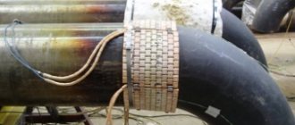
The technological map can cover various types of welded structures, including quite complex ones. These include, for example, welding of thick-walled structures. Such a map is indispensable when laying pipelines and installing bulky structures.
When welding metal of large thickness, with an increase in this size, for example, more than 15-20 millimeters, the volumetric welding stresses in the joints increase. This leads to the risk of cracks in the parts. To avoid this, it is recommended to weld in certain ways, for example, double layer or blocks. These recommendations are indicated in the technological map.
The technological map for the production of welded metal structures also includes rules for monitoring the resulting welded joints. Technological maps are divided into typical and standard. They must be carried out in accordance with existing regulatory documents.
The card for the installation of metal products indicates installation diagrams and the sequence of actions. The requirement for manufacturability is the possible location of the seams during welding - lower horizontal. A good option is to lay the seam “in a boat”.
Semi-automatic welding of metal structures is the most preferable. It is not practical to use fully automatic welding. In mass production, spot welding can be used. If you plan to apply sutures located at a close distance, then you cannot do this right away. You need to wait until the first seam has cooled and then start cooking the second. This will protect the metal from plastic deformation.
The technological map must be drawn up taking into account the available equipment. There is no single sample technological map. You can develop it yourself. However, this document must be created taking into account the requirements of existing regulatory documents in this area. The technological map is subject to mandatory approval by authorized persons. In addition to technical data, it can indicate labor costs.
A typical flow sheet may contain information on how reliable fixation of structural elements can be carried out, information on the possible need to heat up parts before welding, and data on welding parameters that must be set on the equipment used. If there are specific features of the technical process, they are described in detail.
Quality requirements must be confirmed by real figures of possible deviations. A separate section or paragraph may describe what actions he should take if unacceptable defects are detected.
In the technological map, a special section stipulates safety measures. Before work, the welder must familiarize himself with the contents of the technological map and follow its recommendations.
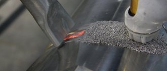
Description of manual electric welding
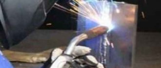
The process of welding metals together is quite complex and can only be done by trained specialists. The process is based on the heat of an electric arc. For electric welding you need:
- electrode
- product to be welded (base metal)
- welding transformer
- power supply
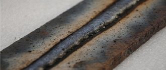
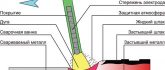
Electricity is supplied to the metal being welded and the electrode from a welding transformer. Under the influence of the temperature of the electric arc, the base metal and the electrode melt, forming a weld pool. It remains in a liquid state for some time. The electrode metal is mixed with the base metal, and the resulting slag floats to the surface, which creates a protective film. After the metal hardens, a weld is formed. To maintain an electric arc, significant energy is required, which is obtained from direct or alternating current sources.
According to the degree of mechanization of the process, electric welding is divided into:
- manual arc
- semi-automatic arc
- automatic
This parameter depends on how the ignition is performed and how the arc length is maintained, as well as how the electrode is manipulated to give the seam the required shape. In this article we will consider manual arc welding. All operations with this method are performed manually by a specialist (without the use of machinery).
Welding of lattice structures
Lattice structures are interconnected rods. This type of structure includes, for example, trusses and all kinds of frames, reinforcing mesh. Frames are flat and spatial, and meshes consisting of mutually perpendicular rods are rolled or flat.
They can all have different types of connections.
The outline of the lattice allows the trusses to be divided into different types. The following types of outlines are available:
- segmental;
- triangular;
- trapezoidal;
- with parallel belts.
For their manufacture, metal up to ten millimeters thick is used. The truss is a system that is not subject to change, consisting of rods that have a rectilinear shape. The rods are connected to each other by hinges - cylindrical or ball. Trusses work in bending mode.
Features of welding lattice structures in the form of trusses lie in the correct centering of the connected rods. This will help avoid the occurrence of additional bending stresses that were not included in the original calculation. The connection of the rods must be such that they experience only forces such as tension or compression.
Elements of metal structures are made from angles, channels and I-beams. Structural elements of a metal truss:
- lower belt;
- top belt;
- knot gusset;
- brace;
- sheet overlay;
- supporting profile;
- fasteners in the form of bolts or rivets.
A node is a place where two or more rods meet. The distance between nodes is called the truss panel, and the distance between the truss supports is called the span. The connection of the rods at the nodes is carried out using a metal sheet called a gusset.
The peculiarities of welding trusses include the sequence in which the various stages are carried out. Welding of truss nodes is carried out from the middle to their edges. If different types of seams are used, butt welds are performed first, and then fillet welds. If the seams have different cross-sections, then the seams with a larger cross-section begin to be laid first. The end of the seam is drawn to the end of the welded element by twenty millimeters.
Assembly and welding of lattice structures will be more convenient when using various devices. The technology for welding lattice structures should be described in the technological map for the product. The length of the weld seams when welding lattice structures should be in the range of 20-40 centimeters.
To minimize the stress in the truss nodes, welding should begin in the middle and then move to its edges. If there are seams with a large and small cross-section, you should start with those whose cross-section is larger.
Types of inverters
An inverter is a device for electric welding that greatly simplifies working with metal. This is a modern type of transformer. With the advent of inverters, it has become possible to make connections that previously would have required bulky and complex units. The electricity required for its operation is directed exclusively to maintaining the arc. Since the inverter is an electronic welding machine, the main load falls on the electrical network (voltage from 220 to 380 W). The principle of its operation is to shift the phase of voltage and increase the shift of current and frequency. First, the inverter changes alternating current to direct current, then it turns it into alternating current again, but with a reduced voltage and increased current and frequency. How to choose an inverter for a novice electric welder ?
A good inverter is distinguished by the presence of a fan. Of course, this helps cool the device and protects against overheating. But the downside is that dust sticks. So you should not buy inverters with the most powerful fans. They will accumulate a large amount of dust inside. In any case, it is necessary to clean the inverter occasionally.
Since the operating principle of the device is based on converting electric current and keeping it in the desired range, an important indicator when choosing will be the built-in element that protects against voltage surges. The optimal level of protection would be 10-15%. It is also worth paying attention to the temperature range of use. If you plan only for household use, then there is no point in overpaying for the European standard EN 60974-1, which allows operation at temperatures from -150 to +150°C. A conventional inverter will be adapted to operate between 0 and +30°C.
Another indicator of the inverter's performance is its uptime. For example, a household unit is capable of welding for half an hour followed by an hour break. Industrial devices are designed for long shifts with short breaks.
When choosing an inverter, you should also pay attention to the voltage range. It shouldn't be too big. The best option is if it is indicated that the device will operate at 220 - 230 V. If the lower limit is less, this indicates low performance at low voltage.
Beam welding
Welding beams provides the most rational solution when performing various building structures. Thanks to their use, it is possible to erect structures several meters high. By welding, you can create beams in which thick, wide chords are combined with high, thin walls. This allows us to reduce metal costs, which makes the structures being built more economical.
Beam classification:
- According to the static diagram, beams are divided into continuous, split and cantilever.
- Based on the type of section, they are divided into composite and rolled.
- Depending on the method of connection, beams can be riveted or welded.
- Based on their location relative to the horizontal axis, beams are divided into symmetrical and asymmetrical.
Solid welded beams come in box and I-section. The most commonly used is welding of I-beams.
This metal connection consists of a wall that is framed by upper and lower shelves. These three elements are connected by welding into a one-piece structure. The advantages of using I-beams include:
- reducing the weight of structures, which helps reduce pressure on the foundation;
- minimizing waste generated;
- increasing the ability to withstand static and dynamic loads;
- good performance characteristics;
- Possibility of use in prefabricated structures.
A type of beams that have a horizontal arrangement are crane beams. Together with the rails laid on them, they form a path along which overhead cranes can move. Crane beams have a T-shaped or I-beam section.
The technology for welding beam structures must ensure strength, density, rigidity and similar requirements. As preparation, it is necessary to carry out calculations for rigidity and strength.
Stages of beam formation:
- Pre-treatment, which consists of cleaning surfaces. Convenient to carry out on shot blasting machines.
- Cutting rolled products into strips of the required thickness. To do this, you can use a thermal cutting machine that has software control. Cutting is carried out according to existing drawings.
- Perform end processing on an edge milling machine. This will reduce the size of the gap between the joints.
- Fixation. It is carried out by performing tacks.
- Welding parts. It is necessary to ensure that the parts are strictly perpendicular to each other and the shelves are parallel. An important parameter is symmetry.
- Correction of the resulting connection. During the process, the geometry of the connection may be disrupted, in particular the appearance of a swelling called mushrooming. Using a roller straightening machine will help fix this.
- Then the surfaces should be degreased and painted. Paint and varnish mixtures will improve the performance of the product.
Welding I-beams is the connection of sections of this profile with each other. It can be done end-to-end or at an angle. To increase rigidity, metal linings are used, which are rectangles cut from sheet metal. This is done on each side.
Before butt welding, pre-treatment of the ends is necessary. For this method, portal or console type equipment is used.
It can also accommodate means to control the resulting connection. In this case, welding is carried out at an angle of 45°. This guarantees high weld penetration. To weld long-length I-beams in small batches, self-propelled welding tractors can be used.
Since I-beams will carry a large load, it is necessary to adhere to the previously made calculations. The developed technology takes into account the correct distribution of efforts.
More difficult to manufacture than I-beams are beams with a box-shaped cross-section. Welding box structures is more labor-intensive, but is widely used due to the fact that the resulting joints have high torsional rigidity. If the box beams are long, they are welded from several sheet elements.
The sequence of actions is as follows:
- Place the top shelf on the rack.
- Weld the diaphragms to it. This will ensure a rigid base is created and the side walls are straight.
- Install, press and weld the side walls.
- Weld the resulting profile in the shape of the letter “P” to the diaphragms using internal corner welds.
- Place the bottom belt below.
It is recommended to weld waist seams using the “boat” method, with the electrode being held at an angle. The scope of application of metal products in the form of beams are bridges, overpasses, viaducts, residential buildings, stadiums, overpasses. Since it is possible to weld beams that have sections of different sizes in different places, many interesting architectural ideas can be realized with their help.
Classification of welding joints
Types of welding joints can be divided into:
- the location of the junction of two workpieces;
- work conditions;
- type of weld;
- process technology;
- thickness of products;
- steel grades
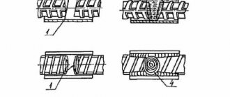
Based on the location of the workpieces, the following types of butt joints are distinguished:
- Tee - the connection of one part to the other with its end side;
- Butt joint - joining of workpieces to each other in the same plane;
- Angled - two products are connected at any angle;
- Overlapping - one workpiece overlaps the second with its edge.
Welding of metal structures is most often carried out using the corner or butt method.
Famous welded structures
The reliability and effectiveness of metal structures contribute to the fact that they are often used in construction. The advantages include their ability to withstand heavy loads, installation in all weather conditions, convenient transportation of individual elements and easy dismantling.
The famous welded structures have been admired for many years. Among the famous metal structures, the first place is rightfully occupied by the famous Eiffel Tower in Paris.
It still attracts huge crowds of tourists with its unusualness. The hallmark and symbol of Australia is the Sydney Opera House. This building stands on stilts driven deep into the ground. The unusual shape of the roof was made possible by the properties of rolled metal such as flexibility and strength.
"Sky Tree" in Tokyo is a television tower, which is based on metal structures connected to each other.
The height of the walls is sixty-eight meters. A building made of metal structures can withstand high-intensity tremors. The outer shell is a combination of steel pipes.
The tallest building in the world, the Burj Khalifa, is located in Dubai. The building frame consists of metal structures.