What is weld reinforcement?
Welding is a reliable joining method, but sometimes welds need additional reinforcement to make them stronger and more stable. And the method of strengthening will depend on what type of welding is made, therefore, when developing welding skills, it is important to simultaneously learn to strengthen it, no matter where it is and what size it is. Read more about what weld reinforcement is, as well as how to implement it correctly, below.
Transition pattern
weld transition pattern is designed to determine the smoothness of the transition from the weld bead to the base metal. The transition smoothness template is used to control the smoothness of the transition of the weld reinforcement to the base metal, when monitoring the geometric parameters of welded joints of steel structures visually and assessing the quality of their mechanical processing. The transition pattern helps to estimate the angle between the plane of the main surface and the tangent plane to the top point of the weld surface. The 120° or 150° fade pattern allows for a visual assessment of the weld geometry in relation to the base metal. A smooth transition of the metal of the front and return rollers to the base metal is very important, as this ensures high strength of the connection under dynamic loads. In fillet welds, it can also be difficult to weld the root of the seam to its full thickness, especially when welding with an inclined electrode. For these seams, a concave cross-sectional shape of the seam with a smooth transition to the base metal is recommended, which reduces the stress concentration at the transition site and increases the strength of the connection under dynamic loads.
According to the governing documents and standards of organizations of JSC AK Transneft (RD-25.160.00-KTN-011-10 “Welding during the construction and repair of main oil pipelines” and RD-23.040.00-KTN-386-09 “Technology for repair of main oil pipelines” and oil product pipelines"), OJSC "Gazprom" (STO Gazprom 2-2.4-083-2006 Instructions for non-destructive methods of quality control of welded joints during the construction and repair of field and main gas pipelines), regulating the shape of the seams, the rollers of the facing layer of the joint should smoothly move to the main surface without undercuts along the edges and ensure that the base metal overlaps on each side at an acceptable distance. Provided that a smooth transition from the weld axis to the surface of the base metal is ensured, an increase in the geometric dimensions of the welds is not a defect. If there is excessive reinforcement of the facing layer of the seam, it should be sanded to the value regulated by the technological map and regulatory documents.
Contents of delivery:
- Fade pattern at 120° or 150° ;
- Passport;
- Certificate of calibration (on request).
Related products:
- VIC kits (Expert, Attorney, Transneft, Basic, VIC-1, etc.);
- Roughness meters (TIME, PCE, Elcometer, roughness samples and kits, etc.);
- Welder templates (UShS, UShK, KMS, ShPS, WG, etc.).
Features of strengthening welds
Reinforcing regular welds is not that difficult, but when it comes to fillet joints, they will require a special approach.
The task will be complicated by the fact that often when strengthening a seam by increasing its length it is necessary to use additional overlaps, ribs, overlays and other structures. And they are selected individually according to the size of the welding area, its location, the material that was welded, the characteristics of the leg, etc.
What does the term seam reinforcement remove mean?
It’s difficult to immediately understand from the name what this means – “seam reinforcement”. So, in the specialized literature this term is deciphered as a part of the deposited metal that forms a convexity.
But the designation in the drawing “remove seam reinforcement” (open circle on a horizontal line, GOST 2.312-72 ESKD) suggests that this same tubercle needs to be eliminated. Most often it is cleaned with a grinder. But you should not forget that reinforcements on corner and butt welded areas must not be removed in the same way. On corner joints, for example, the leg should remain, although on butt joints it is expected to remove everything that protrudes above the surface of the materials being joined.
Removing the reinforcement of a welded joint can also be marked in small letters of the English alphabet, where:
- a is an increase in length, suggesting a frontal overlap of the part.
- b - indicates an increase in the working length (or height) of the leg at which the fillet weld is located.
- c is the internal corner cladding, measured in height, taking into account the presence of additional technological elements, surfacing or special parameters of the frontal parts.
The notation system allows you to better understand not only the features of cooking, but also the materials, as well as the structures made from them, with which you will work.
Quality control of welded joints
Such defects are incompleteness, unevenness and asymmetry of seams.
Incomplete welds (Fig. 176) occur when the electrode wire feed speed is insufficient for a given welding speed, when the bevel angle of the edges or the gap between them increases, when metal flows into the gap, or when the welding current is too high.
Rice. 176. Butt weld with insufficient cross-section (a) and fillet weld with uneven leg along the length (b).
The unevenness of the seam appears due to an unstable welding mode, unevenness of the gap and the bevel angle of the edges, in the locations of large cross-section tacks.
The asymmetry of the seam is a consequence of the inaccurate direction of the electrode relative to the gap or groove. The asymmetry of the fillet weld cross-section, i.e. the difference in its legs, should not exceed the permissible limits.
Typically, the shape and dimensions of the seams are established by standards, rules, technical conditions and are determined by the drawing.
The seams can also be lumpy, mushroom-shaped with side splashes, undercuts, sagging, and burns.
A seam is considered bumpy if the height of its reinforcement exceeds a quarter of the width of the seam. Tuberosity is formed as a result of low arc voltage, excessively high welding speed, and small electrode stickout.
The mushroom-shaped seam is most often observed when welding butt joints and indicates insufficient edge preparation. Mushroom shape is also obtained when welding at low temperatures. Mushrooming, like weld tuberosity, can be eliminated by increasing the arc voltage.
Lateral splashes of metal from the weld pool appear when welding butt seams due to magnetic blast and excessively high arc voltage.
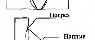
Undercuts (Fig. 177) are recesses in the base metal that are melted during the welding process along the edge of the seam. Undercuts in fillet welds and butt welds with grooved edges indicate excessive penetration due to high arc voltage.
Rice. 177. Undercuts in seams: a - corner, b - butt.
When welding fillet welds “in a boat”, significant transverse displacements of the electrode from the seam line cause undercuts on the side of the displaced electrode and sagging on the other side.
An increase in electrode overhang is also accompanied by the appearance of edge undercuts. Due to an increase in current values and welding speed, undercuts also occur.
Sagging or sagging (Fig. 178) is the name given to excessively deposited metal near the edges that has flowed onto the base metal during the welding process.
Sagging hides lack of penetration of the upper part of the edges, cracks and other defects, disrupting the smooth transition of the seam to the base metal. Therefore, they should be removed and the weld metal underneath them should be carefully monitored.
Rice. 178. Sagging in the fillet weld of an overlap joint.
Burn-throughs are formed due to excessive welding current, a large gap or insufficiently pressed flux pad or copper lining to the edges being welded, as well as when the edges are slightly blunted and the welding speed is reduced. The burn site must be thoroughly cleaned of metal deposits and welded, but the reasons that caused the burn must first be eliminated.
Defects in the formation of a seam worsen its appearance and create stress concentrations. They are discovered during inspection. In some cases, minor formation defects are allowed, which are specified in the instructions and technical conditions for the manufacture of this product.
- Back
- Forward
Weld reinforcement technology
The very principle of intensifying welding is not difficult to understand; it will be carried out by gradual and layer-by-layer surfacing, where each layer will be approximately 2 mm in height. Processing begins from the most difficult places, that is, in those areas where there are any defects - craters, undercuts, sagging.
For electrodes that will be used in the process, there is a GOST standard, which requires a diameter of 4 mm.
Each layer is processed only after the previous one has cooled to 100 °C. Gradually, the welding trace lengthens, then expands a little, thanks to this a reinforcing effect is obtained.
It is important to remember about exceeding the working heights of the legs, which must be avoided, and also not to reinforce the transverse components under load.
This can lead to damage to the entire welded joint, and therefore the entire structure where it was used.
Speaking about the legs of the connections, here after fusing the reinforcing layer, the height of the leg itself should be less than the thickness of the flange from the side of the feather, and also less than the thickness of the profile flange when viewed from the side of the butt. In the second case, the height of the leg should not just be less than the thickness, but less than one and a half thicknesses.
Corner profile processing is carried out only in the direction that was initially chosen. It is not recommended to change it, as it can create excessive stress at the connection point.
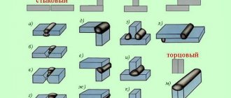
Welded joints and their designations
The relative position of the parts to be welded. Classification of compounds
Table 4
| Types of connections | Image |
| Butt joint (C) | the workpieces are adjacent to each other with their end surfaces and are in the same plane |
| Corner connection (U) | at which the angle of contact between the edges is more than 30° between the surfaces of the parts being connected |
| T-joint (T) | in which the parts are mated at an angle of 90 degrees |
| Lap joint (H) | in which the parts partially overlap one another and are parallel to each other |
| Slotted connection | a slot is made in the workpieces and one part fits into the other |
| Connections with electric rivets | used for making corner, butt, lap and T-joints |
Shape of the outer surface of the welds
The shape of the weld affects:
- physical and mechanical properties of the connection;
- consumption of electrode metal.
Convex seams almost always require additional processing - removal of the convexity mechanically (mill, abrasive wheels).
Welding seams, as well as defects in welded joints, are distinguished by the shape of the outer surface.
Table 5
| Types of seams | Illustration | Symbol | Characteristics |
| Normal(flat) | Economical. Work well under load. | ||
| Concave | Economical. Work well under dynamic loads. | ||
| Convex | The influx of convex metal is not economical. |
Various types of edge removal
Depending on the thickness of the metal, the edges can be made at different angles and from different sides. The following types are distinguished:
- At right angles:
- for steel sheets with a thickness of 4 to 8 mm;
- for one-sided welding for metals up to 3 mm thick;
- for double-sided welding for metals up to 8 mm thick.
- V-shaped (with one-sided bevel), if the metal thickness is from 4 to 26 mm.
- X-shaped (with a double-sided bevel) if the sheets have a thickness of 12 to 40 mm.
- At an acute angle, reduced from 60° to 45° if sheets are more than 20 mm thick.
For good welding, a gap of 4 mm is left between the edges.
Graphic symbols of seam types for various connections
According to the method of performing the welded joint, they are distinguished:
- One-sided welding. This welding for butt joints is performed with edge penetration on the backing, or on weight.
- Double-sided welding. Welding of the second side is carried out only after thorough stripping (removal of the root) by mechanical surfacing of the first side to be welded. Most often, ceiling welding is performed in this way.
- Single layer welding.
- Multilayer welding. To reduce the heat-affected zone or when welding metals of large thickness, welding is performed in a similar way.
Welds of butt joints (shape, designation, example)
Table 6
| Character of the seam | V-shaped | ||
| Without bevel | From beveled edge | With two beveled edges | With two symmetrical bevels of two edges |
| Unilateral | |||
| Bilateral | |||
| Single-sidedwith gasket |
Corner joint seams (shape, designation, example)
Table 7
| Character of the seam | Without bevel |
| Unilateral | |
| Bilateral | |
| One-sided end-to-end | |
| Double-sided end-to-end |
T-joint seams (shape, designation, example)
Table 8
| Character of the seam | Without bevel |
| Bilateral | |
| Double-sided chess |
Lap joint seams (shape, designation, example)
Table 9
| Character of the seam | Without bevel |
| Bilateral | |
| Single-sided intermittent |
According to international standards (ESKD), welds of flat sheets of metal and pipes are classified according to spatial position into:
- horizontal;
- vertical;
- ceiling;
- welded in the lower position.
Depending on this location, it is advisable to use different types of edge removal. Under conditions of careful preparation, namely cleaning, proper adjustment of the edges (blunting the edges - prevents burn-through and leakage of metal, parallelism of the edges - guarantees a uniform seam), the following advantages of the weld can be achieved:
- Economical. Minimum metal consumption for welding.
- Welding speed efficiency. Such edges provide the shortest amount of time for welding in one approach.
- Strength. It is possible to achieve a strength of the welded joint that is not inferior to the strength of the base metal.
Therefore, the technical documentation must necessarily indicate: the type of seam and the type of edge to be removed, which will give the best result when welding the seam.
Radiographic inspection of welds is one of the most effective and common methods for checking joints. Do you want to decorate your home very well? This can be done using metal furniture. Read more about this here.
Do you need to thoroughly clean metal? An effective method is described at https://elsvarkin.ru/obrabotka-metalla/peskostrujnaya-ochistka-metalla-i-oborudovannie-priminyaemoe-dlya-dannyx-rabot/ link.
Reinforcement of butt seams
Strengthening butt welding is complicated by the fact that most often its strengthening can lead to damage to the joint. For example, if the butt seam is made along the entire length or height of the metal components, then no reinforcement can be done at all. Surfacing will create excessive concentration at the melting point, due to which the surfacing can not only deteriorate, but also completely collapse. The thing is that the height of such welds is determined only by the elements being joined and taking into account the structure of the bead of the connection itself. This roller is the protrusion.
If the butt welding still needs to be processed, then you first need to relieve the tension with abrasive tools. After this, the area of the overlays is calculated, with the help of which the seam will be strengthened.
Combination connections
A combined connection can be used in cases of special need, when the stresses in the base metal are greater than those permissible for welds ( Rwy
= 0.85
Ry
). In this case, to ensure equal strength of the welded joint to the main section, the butt seams are reinforced with double-sided overlays (Fig. 10.31). Such a connection is permissible when working with static loads.
Rice. 10.31. Reinforcement of butt seam with overlays
Before applying the overlays, the weld reinforcement (weld bead) is removed with an emery wheel.
When calculating a combined connection, it is conventionally assumed that the stress in the butt weld and overlays is the same and is determined by the formula
σ = N
/ (
Aw + ∑An
) ≤
Rwyγc
,
where Aw
– cross-sectional area of the welds, equal to the cross-sectional area of the elements being connected;
∑An
– total cross-sectional area of the linings;
Rwy
– calculated resistance of the butt weld to compression or tension;
γc
– coefficient of working conditions.
Example 10.6. Calculate a butt welded joint of strips of steel C245 made by manual welding with E42 electrodes with visual control of the quality of the seam. Tensile force N
= 1400 kN.
The cross-sectional size of the strips is b
×
t
= 300 × 20 mm.
The design resistance of steel for a rolled product thickness up to 20 mm inclusive is Ry
= 240 MPa, standard tensile strength
Run
= 370 MPa (see Table 2.3).
Operating conditions coefficient γc
= 1.0. The welding mode is normal.
We make a straight butt seam, bringing the ends of the seam to the strips. The calculated resistance of a butt weld in a tensile joint (the quality of the seam has not been checked by physical control methods) is determined by the formula
Rwy
= 0.85
Ry
= 0.85 240 = 204 MPa = 20.4 kN/cm2.
Checking the strength of the butt seam:
σw
=
N
/
Aw
= 1400 / 60 = 23.33 kN/cm2 >
Rwyγc
= 20.4 kN/cm2,
where Aw
=
tlw
= 2 30 = 60 cm2;
lw
=
b
= 30 cm.
The weld strength condition is not met.
We reinforce the welded joint with two rhombic pads of minimum thickness, each with a cross-section of 250×6 mm.
Overlay area An = tнbн
= 0.6 · 25 = 15 cm2.
To reduce stress concentration, the width of the overlays should not differ greatly from the width of the joined sheets - bн
=
b –
2 2.5 = = 30 – 5 = 25 cm.
Determine the stress in the butt weld:
σ = N
/ (
Aw +
2
An
) = 1400 / (60 + 2 15) = 15.56 kN/cm2 <
Rwyγc
= 20.4 kN/cm2.
Force absorbed by each pad:
Nн = σ An =
15.56 · 15 = 233.4 kN.
We set the maximum leg of the seam equal to the thickness of the overlay, kf
=
tn
= 6 mm.
We determine the calculated shear resistance of the weld during manual welding:
Rwf
= 180 MPa = 18 kN/cm2 – when calculating the weld metal, taken according to table. 2.7;
Rwz
= 0.45
Run
= 0.45 · 370 = 166.5 MPa = 16.65 kN/cm2 – when calculating the fusion boundary for the metal.
Weld penetration coefficients are taken for manual welding: βf =
0.7 and
βz =
1.0
.
Coefficients of weld operating conditions γwf = γwz =
1,0
.
We determine which of the checks (for the weld metal or for the metal of the fusion boundary) is decisive:
βf Rwf
= 0.7 180 = 126 MPa <
βz Rwz
= 1 166.5 = 166.5 MPa.
We make calculations based on the weld metal.
The force in the overlay must be absorbed by welding the overlay, from which we determine the required total length of the fillet welds required to attach the overlay to one side of the joint:
Σlw = Nн
/ (
βf kf Rwf γwfγс
) = 233.4 / (0.7 · 0.6 · 18 · 1 · 1) = 30.87 cm.
We accept two seams (taking into account defects at the beginning and end of the seam, 0.5 cm each) in length
lw
=
Σlw
/ 2 + 2 0.5 = 30.87 / 2 + 1 = 16.44 cm ≈ 17 cm.
Reinforcement of corner seams
Here, strengthening of welded joints will be carried out by increasing the length or thickness of welded deposits. The first option is used more often, since it is better to increase the area and distribute the stress over it, rather than concentrate it.
The length and thickness of the created welds, as well as the thickness of the reinforcing layer itself, are calculated mathematically. Thus, they can be determined by the difference between the design force in the welded joint and the load-bearing capacity of this weld. It is important to take into account here that the design force will always be affected by its displacement relative to the center of gravity of the element’s section.
All formulas, symbols for them and tables with suitable values are in GOSTs, therefore in most cases everything can be calculated with maximum accuracy. And the accuracy of the calculations will make it possible to more accurately strengthen the welds.
Sometimes strengthening of welded corner joints occurs with the introduction of additional parts, but this is not necessary. This method will only be justified if there is room to add new layers. Basically, standard welding equipment with electrodes correctly selected in diameter is used.
If you increase the connections by increasing their length, then the load on the welded fasteners should not exceed the design resistance. Thus, the strength of the deposits will increase in proportion to the increase in the length and thickness of the connection.
This method is suitable for any fillet welds, except transverse ones.
Also, in order to make the welded area longer, gussets can be used, which are welded to the main elements using butt welded joints.
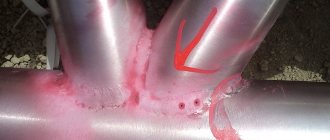
It is important to be careful when forming the back side of the seam, since if the heat supply is uneven, lack of penetration will appear, which will negatively affect the characteristics of the part.
But the main defect that appears in such situations is called “excess convexity,” that is, excess deposited metal on the face of the materials. This excess of convexity occurs most often due to non-compliance with the welding technique itself and the high feed speed of the filler wire. It can be corrected by sanding or rolling with rollers.
Making a perfect weld is an impossible task, but you can always strive for it. Therefore, you need to not only have good welding skills, but also understand the small but important nuances of the welding process. This is precisely the ability to make a high-quality strengthening of an already made connection.
Source
Increasing the strength of welded joints
0
The strength of welded joints is increased by constructive (rational arrangement of seams relative to the acting forces, appropriate shape of seams) and technological (protection of the seam from harmful effects during welding, heat treatment, hardening treatment by cold plastic deformation) methods. Constructive methods for increasing strength are shown in Fig. 8.
Views 1–3 show the sequential strengthening of the flange welding unit loaded with torque by increasing the diameter of the circumferential weld. The shear resistance (proportional to the square of the connection diameter) in design 2 with the same seam cross-section is 7 times, and in design 3 it is 18 times greater than in design 1.
With the correct design of the seam, additional fastenings [on threads (type 4), interference fits (type 5), etc.] are unnecessary.
In centering joints, the parts to be welded are installed on landings with a gap of f8, f9, e8, e9, d9, d10. If more precise centering is necessary, h7, h8, h9 and transitional k7, k8 are used.
It is advisable to unload the welds, transferring the perception of loads to sections of the whole material and leaving only the function of connecting parts to the welds.
Some examples of unloading welds are shown in views 6, 7 (rod loaded with axial force) and views 8, 9 (thrust flange).
In the attachment of the cover to the shell of a cylindrical tank loaded with internal pressure (type 10), the welds of the cover and shell are subject to bending and shear by pressure forces. In the improved design 11, the shell weld is relieved by inserting the shell into the flange, and the bottom seam is relieved by clamping the bottom between the shell and bottom flanges.
Power seams should preferably be loaded in shear and tension, eliminating bending.
The design of a welded rod 12 loaded with a transverse force P is impractical. Force P, rotating the rod around point O, causes high tensile stresses in the area opposite to this point. In addition, the seam is subject to shear.
Design 13 is somewhat better, where the rod is centered in the socket of the part, due to which the seam is relieved from shear. However, the dangerous section of the rod is weakened by the weld.
In design 14, bending and shearing by force P are absorbed by intact sections of the rod that are not weakened by welding. The seam is practically unloaded from the action of force and serves only to fix the rod in the part.
It is advisable to unload the seam of the welded wall (type 15), bent by force P, by introducing a rib (type 16).
The bending of the butt seam (type 17) can be eliminated by introducing an overlay (type 18), the seams of which work primarily in tension. The butt seam in this design works in compression.
The butt joint of the corners (type 19) is not strong enough. It is more expedient to weld the corners along the plane of the shelves (type 20) with reinforcement (for difficult working conditions) with gussets (type 21).
It is advisable to weld the gussets not end-to-end (type 22), but overlapping (type 23).
It is recommended to position the welded ribs so that they work not in tension (type 24), but in compression (type 25), which almost completely relieves the load on the welds.
Views 26-29 show the sequential strengthening of a sheet joint loaded with a tensile force P and a bending moment Mizg. A comparison of the strength of various structures is given in table. 3.
The strength of the butt joint 26 is taken as one.
Welded sheets, overlays, gussets, etc. of large length and small thickness, it is advisable, in addition to welding along the contour, to be connected to the main part by spot welding (type 30) in order to avoid sheets falling behind when the system is deformed.
Slanted lap joint welds (type 31) subjected to tension experience additional shear loads along the weld line. In a balanced connection with a two-way bevel (type 32), the seams are relieved from shear.
Views 33-36 show the design of the channel welding unit. In connection with a channel located with flanges up (view 33), the upper sections of m vertical welds are subjected to high tensile stresses from the action of force P.
In a design with a channel located with flanges down (type 34), the force is absorbed by a horizontal seam n of great length; the weak end sections of vertical seams experience compression.
In the design with the connection of the channel into the tenon (type 35), the welds are unloaded from bending by force P; the bending moment is perceived by the flank seams and the transverse seam t experiencing shear. View 36 shows a connection reinforced with a gusset.
Eccentric application of forces that cause bending of the seam should be avoided.
Beaded seams in knots subjected to tension (type 37) experience bending. It is more expedient to design with a butt seam (type 38). In the unit for welding the bottom to a cylindrical tank with a flange (type Z9), the weld seam is subject to bending under the influence of internal pressure. The butt weld (type 40) experiences predominantly tension.
Avoid placing welds in high stress areas.
In welded beams subjected to bending, it is advisable to place the seams not at the flanges (type 41), but at the neutral section line (type 42), where the normal stresses are the smallest.
In connections subject to cyclic and dynamic loads, the location of welds should be avoided in areas of stress concentration, for example, in transitions from one section to another (View 43). Under these conditions, the seam is subjected to increased stress. In addition, stress concentration increases due to the heterogeneity of the weld structure.
An improved design is shown in view 44.
If it is impossible to move the seam beyond the stress concentration area, then it is recommended to use concave seams (type 45) with deep penetration, achieved by short arc welding.
The seam profile should be as symmetrical as possible with respect to the action of loads. In T-joints subject to tension (type 46), it is advisable to use double-sided seams (type 47). Lap joints (type 48) should, if possible, be replaced with butt joints (type 49). In butt joints, it is advisable to use double-sided edge preparation (type 51), since in joints with an asymmetrical seam (type 50) the force flow is bent, accompanied by stress concentration.
The fatigue resistance of welds can be significantly increased by mechanical processing, giving the seam a rational shape that reduces stress concentration.
It is advisable to process fillet welds along the radius with a smooth transition to the surface of the parts being connected (view 52). Butt seams are processed flush with the surface of the product, removing beads (reinforcements) both from the side of the main seam and from the side of the weld (type 53).
To smoothly connect the seam to the walls of the product, in most cases it is necessary to trim the walls simultaneously with processing the seam (dashed lines in views 52, 53), for which allowances (c) should be provided for processing.
In Fig. Figure 9 shows the fatigue curves of a butt joint with “reinforcements” (lower curves) and after their removal by mechanical processing (upper curves). Thin lines are fatigue curves for the connection without heat treatment, thick lines are after stabilizing heat treatment (annealing at 670°C). As can be seen from the graph, removing the “reinforcements” increases the cyclic strength by approximately 2 times, and heat treatment by 15-20%.
The cyclic strength is significantly increased (by 30-40%) by smoothing the welds with a tungsten electrode in an argon atmosphere.
Strengthening the seams by plastic deformation in a cold state (rolling, shot peening, embossing with a pneumatic tool with beam stampings) makes it possible to bring the fatigue resistance of the seam to the strength of the base metal.
How to remove a weld inside a round pipe
Hello, dear readers and DIYers!
In a recent article, the author of the YouTube channel “Fireball Tool” told you about ways to remove a weld from profile pipes.
No less interesting is the technology for removing a rough weld from the inside of a round pipe.
Of course, it would be possible to apply the old technology by running a seam cutting device through the pipe, as described. But most likely this method would not work, since in the case of a round pipe there is nothing for the holder with the cutter to rest on.
In this case, the cutter will most likely begin to rotate in a circle as the tool passes through the pipe.
Manufacturing process. The master is looking for another way. He used a band saw to cut a piece of round steel that he was going to feed through the pipe. The diameter of the round timber should be 0.5-1 mm less than the internal diameter of the pipe being processed.
Instead of round timber, you can also use a steel tube of the same diameter, welding both ends tightly.
But this material is too soft to be used as a cutter. Therefore, the master is going to weld the cutting edge onto the leading edge of the round timber, along its entire circumference.
Later, the cutting edge will be sharpened on a grinding machine.
He uses a TIG welder to weld this high-strength metal onto the base. This technique will allow him to determine with great accuracy the location, quantity and thickness of the deposited material.
For the convenience of welding work, a special rotary welding table is used. The production of a similar table was described in one of the articles.
The craftsman deliberately makes the weld around the edge voluminous enough so that it can later be processed on a grinding machine.
I thank the author for an interesting way of removing welds from pipes.
Good mood, good health, and interesting ideas to everyone! Subscribe to the telegram channel
site so as not to miss new articles.