SHARE ON SOCIAL NETWORKS
FacebookTwitterOkGoogle+PinterestVk
From this article you can learn how to make a metal cutting machine with your own hands at home using the simplest materials. All stages of creating structures based on a cutting disc or grinder are described here in detail: preparation of materials and tools, calculation formulas, detailed step-by-step instructions, as well as related information with useful tips.
A do-it-yourself metal cutting machine will allow you to obtain equipment that is ideally suited to the owner’s needs
Classification of cutting machines
Disc metal cutting machines are divided according to various factors. The main division is based on the number of working parts of the tools (cutting discs). These include:
- Installations with one cutting disc. They are characterized by low power and low efficiency. Used for cutting metal profiles, pipes, fittings, and other elements. Expensive models are equipped with a regulator for changing the position of the cutting part relative to the workpiece at angles.
- Units with two cutting discs. They are distinguished by high performance indicators. One working part is stationary, the second is fixed on guides for movement. Used at large enterprises for high-speed execution of technological processes.
In home workshops, it is better to use a power tool with one cutting disc. It is enough for cutting various materials and preparing construction consumables. To make it more convenient to work, you need to take care of purchasing or making a work table on which the long edge of the workpiece will lie.
Another option for classifying cutting machines is the option of feeding the working part. Among them are:
- Front feed.
- Bottom feed.
- Mechanisms with a pendulum stroke of the disk.
Depending on how the circular saw is fed, the design of the entire unit changes, and features of its control appear.
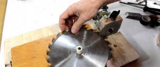
Cutting tool
As a cutting tool, the saw uses circular saws, abrasive wheels of various diameters and seats. In this case, you need to look at the saw’s operating manual; the recommended blade parameters are indicated there. Thus, the Makita LC1230 saw uses a disk with a diameter of 12, with an inch fit, 25.4 mm and a number of teeth of 60 for cutting. This could be a Makita saw blade, 305x25.4x60, for example, Makita B-29393. Discs from other manufacturers that meet the technical specifications can also be used. Cutting is usually done with carbide-tipped discs at the ends of the disc teeth.
Construction of cutting machines
Before you start assembling homemade equipment for cutting metal workpieces, you need to understand what parts the machine consists of. The main elements include:
- Bed, frame. A stable frame on which other parts will be attached.
- Desktop.
- Vise for clamping pipes and fittings.
- Electric motor with protective casing.
- Handle for changing the position of the cutting disc.
- Panel for turning on and off the installation.
The remaining elements are optional.
Desktop Design Requirements
The cutting unit must have a working table of optimal dimensions. The required parameters are: 701*1000*900 mm. The table is welded from a corner measuring 25*25 mm, after which it is covered with a steel sheet having a thickness of 3 mm. Slots are made in advance in the sheet at the point where the circle rotates.
A clamp with a rotary clamp and a rotary stop are fixed at the workplace. Such a homemade mechanism allows you to cut products at an angle and perpendicularly.
Any cutting machine for metal requires compliance with a number of conditions during its installation:
- adjustment of the rotation angle is required (its location must be perpendicular to the surface of the desktop);
- the master needs to protect his hands from damage by installing covers around the disk and rotating elements;
- it is important to calculate the rotational speed of the circle in advance;
- equip the handle with an emergency stop button, which, when pressed by hand, instantly stops the operation of the entire mechanism;
- Place the wheel feed force in the cutting zone.
Rotation angle adjustment
Technology for creating a cutting machine from an angle grinder
A simple way to make a homemade metal cutting machine is to use an old grinder as a base. You need to create a base, a work table plate with a vice. Secure the power tool to a movable guide and install a bearing to allow the saw blade to move vertically. Check the functionality of the homemade unit before starting work. It is important to leave the safety guard in place on the angle grinder to reduce the risk of injury.
You need to prepare tools and consumables in advance:
- Metal rods.
- Sheet steel.
- Ball bearings.
- Metal tires.
- Bolts, nuts, screws.
- Profiled pipes.
- Little Bulgarian.
- Electric drill with drills of different diameters.
- Welding machine.
The drawings can be viewed on the Internet. Welding the parts together is more reliable, however, if it is not possible to work with this device, you can fasten the parts to threaded connections.
Grinder cutting machine
Console (pendulum)
The cantilever part of a metal cutting machine is one of the most important. In addition to the fact that it must be carefully balanced, securely welded in compliance with all the required dimensions, it must also move strictly perpendicular to the work table. The basis for mounting the pendulum are two vertical posts with slots for the pendulum bushing (diameter 10-12 mm). It is best to make them from a steel square of 40x40 millimeters. The height is approximately 80-100 millimeters, but you can calculate your own version.
A bushing shaft is installed horizontally in the holes of the racks, to which a rocker arm is welded, consisting of two levers, the ratio of which is one to three. A platform for installing the electric motor is welded on the short arm. On the long arm there is a cutting wheel drive shaft. The ratio of the lengths of the levers is approximate; it must be calculated so that in the non-working position the weight of the engine outweighs the weight of the assembled saw part (with protective covers). To bring the disk of the switched-on machine into contact with the metal, it is necessary to apply a small but noticeable force.
For ease of operation, a return spring is attached to the bottom of the engine platform, and the upward deflection angle of the pendulum is adjusted by a cable or chain, fixed at one end to the table and the other to the bottom of the long lever.
Materials and tools
To make a more powerful machine for cutting metal parts, you need to use a separate motor. In addition to this, it is necessary to prepare drawings of the assembled device, tools for making homemade cutting equipment, and consumables. These include:
- Metal profiles, corners, plates for making a frame with a work table.
- Bearings, shaft, two pulleys.
- Electric drill, grinder, welding machine.
In addition, you will need fasteners and accessories for power tools.
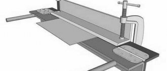
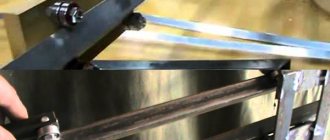
Assembly saw for metal
Hello everybody! So I had a need to create a small device for cutting a metal profile strictly at 90 degrees (and not only).
At first, of course, there was the thought of buying this unit, but unfortunately, I didn’t find anything small (I don’t need to cut anything thicker than a 60*60 pipe) and especially reliable. everything is normal only from a circle diameter of 330 mm. Accordingly, the weight, size and price left much to be desired.
For angle grinders up to 230 mm, only not very convenient universal stands were offered, the backlash of which was simply horrifying.
So, after numerous brainstorming sessions, the following design was born, which I embodied first in the form of a 3D model, and then in metal. I want to say a special thank you to @Ya for his idea of using a threaded connection as a backlash-free friction bearing! This article was precisely the starting point of my idea.
But it didn’t bother me, both in purchased and homemade devices, that the angle grinder is located inconveniently and you have to struggle to start and stop it, so I decided to place it along the swing. This method has a disadvantage - the overall size of the gearbox in this direction is larger, therefore the minimum diameter of the remaining abrasive wheel is larger, so the wheels will have to be changed more often. But after thinking about it, I decided that it was not so significant.
Here is the appearance of my mounting saw at the design stage:
The MNA-1.8-230 from Diold was taken as the basis. Why? Yes, I just heard a lot of normal reviews about this instrument, it is cheap enough to be torn to pieces, its handle is made separately from the body, which made it possible to disassemble it the way I wanted; The angle grinder has 3 places for attaching an additional handle for the 12th bolt - a prerequisite and a guarantee of good accuracy of the future machine.
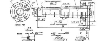
So, let's move on to production. Well, where would we be without drawings:
Metal was purchased: profile pipe 40*40*2, 40*20*2; corner 50*5 and 40*40; strip 50*5 (of course I really wanted to use a sheet 5 mm thick, but we only sell it whole - 2.5*1.2 meters.. I don’t need that much)
The first step was to cut out even blanks of all elements, that is, their overall dimensions:
After that, I started cutting out shaped elements, drilling holes and making welding preparations:
I will say that this was one of the most difficult and painstaking processes, since the holes for the pin, which became the axis of rotation of the swing, had to be done strictly coaxially and evenly. and the rest of the details were performed with the highest possible precision.
Then the process of assembling the base began. here the corner clamps purchased a week before came to the rescue - a very necessary thing in the household. As a result, I got a high accuracy of the resulting rectangle:
I can imagine what it was like for the neighbors when I cut off the seams on all sides with my little angle grinder... by the way, at this stage I realized the beauty of using earplugs. Now I won’t part with them!
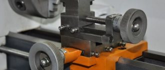
Now it’s the turn to start the welder and collect this whole pile of metal together. The previously experimental angle grinder was disassembled and instead of a handle, a plug with ventilation slots was made. it can be clearly seen in the photograph:
To fix the elements on the angle grinder, and subsequently to hold the angle grinder on the swing, I used hexagon socket bolts, cut on my machine. True, I took a regular bottom bolt, since the bottom fastening uses a strip, and its head height is lower, this allowed me to save space for the stop.
The entire swing has already been assembled on tacks and is awaiting final welding:
Welding a swing is nothing special, that's all. that all the seams were welded apart from the center in half, to minimize the thermal effects of the metal.
Let's put the welded swing aside and start assembling the base and installing the racks on them:
Everything here is also banal and simple. Unless you have to try to collect everything carefully, so as not to have to redo everything from the beginning.
After welding the racks, you must definitely place the swing with the grinder in its rightful place and see what happens:
Having looked at it enough, you can start welding it. There are two key points here:
- You need to buy a cutting wheel for an angle grinder with a thickness of 4 mm in the store and be sure to check it in the store for evenness. The accuracy of vertical metal cutting will directly depend on this. I came across an unsuccessful circle and therefore the deviation of the cutting plane was 0.8 degrees from the vertical (on a 40*40 profile pipe this is only 0.6 mm, so I’m not too upset).
- Carefully select the base plane relative to which this same angle will be set.
Since this process was very painstaking, no intermediate photographs were preserved. Here is the result after everything is exposed and scalded:
The next stage was the installation of limiters for raising and lowering the swing, as well as the installation of return springs. I thought. that four of them would be needed, so I welded the appropriate number of bolts. but it turned out that two were enough. An ordinary door spring was used as a spring, but cut in half. There is one small trick here: in order to carefully bend the coils to secure the spring, you need to release the bend. To do this, I used a pocket burner based on a gas canister for refilling lighters (thanks to @koldun_1616 for the idea).
Now you can start installing the wiring. I used the power cord from an angle grinder. In addition, I bought a soft start unit in advance, I thought that it would not be superfluous. And I wasn’t even wrong! great stuff! There is less load on the gearbox (and the neighbors are calm that the light is not blinking). The soldering process was also left behind the scenes, but there is a photo of the result:
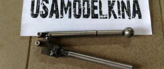
Now it’s time to make the handle with the start button. I used my original one again, because I couldn’t find a more successful design in the tool spare parts store, especially since I wanted one with an accidental activation lock.
There was a lot of fuss with this pen. It consists of 3 parts made of 12 mm plywood. The biggest challenge was cutting out the blind containers for the body of the button, since I don’t have a router yet, I suffered with a groover and a knife. The assembly process and the final result are visible in the photographs:
During the design, I tried to comply with possible ergonomic aspects, such as protection against pinching and accidental injuries, but there was one point I could not eliminate - the gap between the swing and the stop for the part being cut is very small. There is no way to increase it, but the hand just begs to go there. to press the workpiece against the fence. We have to constantly remember this.
Now it's time to put the handle in place and hide the wires. It turned out very nice:
Well, I finally need to breathe life into my first homemade machine! We plug it in... the idle start was successful! nothing sticks anywhere! Already encouraging! Let's start the first test (and how scary it is...):
This is the moment of truth! the machine is working! True, in the video the cutting process seems very long, but it was simply scary to press harder. Then I bought a more expensive and smoother disc. the speed of one cut in operating mode is about 15-20 seconds.
As was said on the forum, the first chip indicates that the project is finished, and then improvements and improvements begin.
Here’s what else I’ll definitely do, but I just don’t have time now, since the machine is working hard with me to create a metal cabinet with mezzanines in the corridor (that’s what they were made for):
- Make a stop for the workpiece, which will be moved to a position for cutting at an arbitrary angle;
- Additional protective cover for the working disk;
- Garbage container for cutting waste;
- Painting the machine with hammer enamel;
3D Drawings in Compass 11 sp1 format are located in a file archive.
Photos in original resolution are in the gallery.
P.S.: Please do not scold me for spelling and punctuation, I did my best.
The quality of the photos is of course not very good, I just didn’t have a camera on hand, I took it on my mobile phone, but I tried to fix it in Photoshop as much as I could.
I will be glad to have any questions and will try to explain if anything is interesting or unclear.
How difficult it is to create a detailed report on the work done!
But I made it through! HOORAY! Modified February 25, 2011 by Bayk
Procedure for making your own machine
You can assemble a high-quality machine with your own hands only by studying each of the key elements separately.
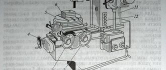
Engine
The power of the electric motor depends on how hard the metal will be processed and how often the homemade machine will be used. The optimal power range is from 1.5 to 3 kW. The number of revolutions must be at least 2500 per minute. We must not forget about the required current strength. For a home workshop, the best connection option would be a common 220 volt network. It is advisable to choose an engine with the ability to change the number of revolutions.
Separately, we need to talk about the diameter of the cutting discs. Optimal sizes are from 300 to 400 mm. The larger the disk, the more revolutions it requires for high-quality processing. However, on any consumable, the maximum number of rotations per minute that are allowed during cutting is indicated. Most often, the maximum is at 4400 rpm.
Drive unit
To make the drive, you need to use a belt drive. To make it, you need to find two pulleys that will be equal in diameter. Attach one pulley to the shaft from the electric motor. The second is installed on the drive shaft of the abrasive disc. Next, the shaft of the equipment is fixed on two bearings. The motor must be installed on the back side of the finished pendulum. For this, 4 bolts are used. The fasteners must be installed in slots that allow the engine to be moved by 5 centimeters. This will allow you to select the optimal belt tension. With a moving engine on a homemade machine, it is easier to change consumables and belts.
Console pendulum
The console is a key piece of equipment, the assembly of which determines the accuracy of the cuts. For the base of the pendulum, you will need two bushings, which must be made from a metal square measuring 4x4 cm. Their height should not exceed 10 cm. Holes must be made in the racks to secure the bushing shaft. Next, a rocker arm is welded to it. A surface is installed to secure the electric motor. The lever for lowering the disk to the workpiece is calculated depending on the desire of the person.
Desktop
Principles of making a desktop:
- Make a cut through which the disk will pass while cutting metal workpieces.
- Dimensions are selected depending on the stroke of the pendulum and the diameter of the equipment.
- Additionally, you can build a broaching mechanism.
- Install a side clamp so that you can clamp the workpieces while cutting.
The optimal thickness of a metal sheet for a desktop is about 4 mm.
Homemade desktop
The manufacturing process must be performed in the following order:
- Manufacturing the shaft on which the cutting disc and drive pulley will be installed. Assembling the entire assembly and installing it on the pendulum (I call the pendulum the upper, movable part of the machine on which the cutting disk and motor are installed).
- Engine installation. Connecting the motor to the cutting disc shaft with a drive belt.
- Manufacturing of protective covers for the cutting disc and drive belt.
- Manufacturing the pendulum mounting shaft
- Manufacturing of a machine frame with a device for securing the workpiece, a spark arrester, preparation for installing electrical...
- Installing the pendulum on the frame.
- Wiring.
- Test run. Adjustment and debugging.
Before starting to make the cutting machine, I studied the experiences of other people, from which I realized that:
- The motor must be installed at least 3 kW. if the cutting disc is 400 mm.
- The disk speed must be at least 3000 per minute.
- It is more convenient to place the disc on the shaft on the right, and the drive pulleys on the left; this will not allow the nut securing the cutting disc to turn loose during operation.
- bearings for the cutting disc shaft are suitable for both 205 and 204 (I used 205)
I installed a 3-phase motor, since I have a voltage of 380 V in my workshop. If you have a voltage of 220 V, in this case you will have to install starting capacitors; there is a lot of information on how to do this on the Internet.
Below are some photos of the manufacturing process.
The protective cover lifts up to replace the used disc with a new one. To do this, you need to unscrew just one M8 bolt from above.
Possibility of adjusting the tilt of the rocker using metal plates. I did not install bearings on this shaft, but simply drilled holes for lubrication on top and plugged them with M6 bolts.
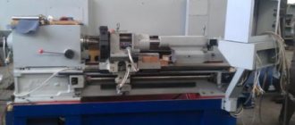
I borrowed the vice for clamping the workpiece from an old factory-made cutting machine, but I had to modify it a little. In this vise, the clamping screw nut can be divided into two halves, which is very convenient when installing and removing a workpiece.
There is no need to create a return mechanism; just change the alignment of the rocker shaft.
Spark arrester. 97 percent of all sparks end up in a removable container. Using the stop bolt (bottom), you can adjust the maximum angle of inclination.
I would like to explain how to calculate the required pulley diameter.
We will assume that the cutting disc should rotate at a speed of 3000 rpm. The discs contain information about the maximum permissible rotation speed of 4400 rpm. So you decide for yourself at what speed your disk will rotate, the main thing is that it should not exceed 4400 rpm.
To calculate pulley diameters you need to know:
- engine speed
- cutting disc shaft rotation speed
Calculation example:
Our engine rotates at a speed of 1500 rpm.
The cutting disc should rotate at a speed of 3000 rpm.
We have a pulley for the cutting disc shaft with a diameter of 65 mm.
What kind of shaft should be on the engine?
- We calculate the length of the perimeter of the existing shaft: we multiply the number Pi (3.14) by the diameter. 3.14 x 65 mm = 204.1 mm (shaft perimeter length).
- We multiply the resulting number by the required shaft speed: 204.1 mm x 3000 rpm = 612,300 mm/min.
- we divide what we got by the engine speed: 612,300 mm/min / 1500 rpm = 408.2 mm (perimeter of the engine pulley)
- we divide the result by the number Pi: 408.2 mm / 3.14 = 130 mm we need a pulley of this size in order to spin the cutting shaft at a speed of 3000 rpm.
In this way you can also calculate the size of the pulleys if:
- Do you have pulleys of other diameters available?
- You only have a suitable pulley for the engine and you need to select a pulley for the cutting disc shaft
- You don't have pulleys yet and are planning to buy or make them.
Operating a homemade machine
When using a homemade cutting machine, you must follow a number of operating rules:
- Wear safety glasses and gloves to protect yourself from metal shavings.
- Periodically lubricate moving parts with machine oil.
- Clean work surfaces from accumulated debris after work.
- Check the integrity of the equipment before starting the engine. Change discs depending on what kind of metal will be cut.
- If extraneous sounds appear, disconnect the unit from the network and do not turn it on until the cause of the breakdown is determined.
- Don't forget to install the protective cover. It is important to make a mechanism that will move it while the pendulum moves down.
- Do not try to cut heavy-duty materials; work for a long time at maximum speed.
Homemade equipment is not intended for mass production.
Metal cutting machines are used both in industrial enterprises and in private workshops. For construction and home improvement, you can assemble a unit for cutting metal blanks with your own hands. Prepare tools, consumables, draw a drawing. Next, carry out the work and check the functionality of the main elements before starting metal processing.
Engine
Depending on the required power of the metal-cutting machine and the scope of its use, we select the engine power. It should be in the range of 1.5-3 kW. If you plan to use a cutting machine in a home workshop, a small metalworking shop, where cutting profile pipes, fittings, angles or other rolled products is done relatively rarely, and thin-walled metal is used as workpieces, a power of one and a half kilowatts will be enough. For small-scale production, work on a construction site, or the manufacture of frames for any purpose, a more powerful engine will be required.
If you have a three-phase motor with a power of about 3 kilowatts, it can be connected to 220 volts using a star circuit instead of a delta circuit. But it must be taken into account that its power will decrease by 25-30%. The main thing is that the speed indicated on the nameplate will be maintained.
To install on a metal cutting machine, the engine must have a speed of 2500-3000 per minute. This is due to the fact that it is at these speeds that the cutting disc operates optimally.
For a homemade metal cutting machine, circles with a diameter of 300-400 millimeters are used. Here, too, you need to proceed from the needs of production. You shouldn’t chase too large a disk diameter - the farther the working edge is from the center, the less cutting force, and a more powerful engine will be required. The optimal ratio of engine power and disc diameter is 2 kilowatts at three thousand revolutions and 300 millimeters in diameter.
A self-made metal cutting machine must first of all be safe. The cutting discs indicate the maximum number of revolutions at which they can be operated. As a rule, it should not exceed 4400 rpm. If it turns out more, the disk may collapse, which is unsafe. If the number of revolutions is less than 3000, then the cutting speed will be insufficient, and the disk will overheat and wear out. It is these figures that should be taken as the starting point for calculating the power transmission.
Tools
0 votes
+
Vote for!
—
Vote against!
Working with a cutting tool, for example, a grinder, many craftsmen understand how much easier it is to cut metal using a simple machine - both the work is more convenient and the cut line is ideal. But when looking at the prices for a cutting machine for metal, even the most primitive used one, there is a desire to make something like this device yourself. There are several ways to make a cutting machine with your own hands, for example, using a grinder or a disc. All designs have their disadvantages or obvious advantages.
Table of contents:
- Use of cutting machines in everyday life
- Classification of machines
- The manufacturing process of a machine based on a cutting disc
- The manufacturing process of a machine based on a grinder
Use of cutting machines in everyday life
When working with metal, it is impossible to do without welding, cutting, grinding and other types of processing. The ability to have the simplest machines for woodworking and metal on your farm is a huge help to the home craftsman. In those places where it is difficult to reach for work, for example, cutting off a metal staircase or changing something in the attic structure, you will need a grinder or a circular saw. And cutting equal pieces of reinforcement, rods, small pipes and all kinds of metal workpieces is much easier to do on the working surface of the machine.
The same cutting tank can be used for other purposes to cut aluminum, plastic and other synthetic materials. However, it is not recommended to use metal cutting machines for woodworking purposes. Considering the small size of a household metal-cutting machine and the general simplicity of this design, it will not be difficult to place it on your estate.
To operate the machine, you will need a well-lit area in the yard or garage, an outlet and a flat floor surface. And if it is no longer needed, it can always be taken to the workshop, pantry or utility room until the next use on the farm. Some designs of homemade machines can be assembled and dismantled, the frame or base of the structure will remain intact.
A homemade cutting machine can also not only be used at home, but also rented out in order to recoup the costs of its production - in a word, this is a very profitable device.
Classification of machines
Structurally, all metal-cutting machines combine an engine with a transmission, a cutting disk and the working surface of the machine. There are drawings for a cutting machine on most sites dedicated to various homemade products. Knowing the basic principles of operation of this device, it is easy to make your own adjustments in order to use the materials and mechanisms that are already on the farm.
1. The power of the motor used depends on the expected performance, and it is important to decide on this before making a cutting machine. Most ready-made cutting machines have quite high power - up to 2000 W. Although a machine for domestic use may have smaller parameters, you should not forget that the metal is the same everywhere.
2. To maintain the power of the engine on which the machine will operate, it is important to choose a suitable kinematic transmission method. The most common are belt and friction friction transmission, each method has its own advantages. Gear transmission is gear, worm, chain, but the latter option is the most popular. Belt drive produces the least noise and is most often used on homemade machines, but for more precise machines it is not suitable due to the likelihood of the belt slipping. However, with any machine design, it is important to remember to comply with safety precautions.
3. It is advisable to equip even a homemade machine with a vice - to ensure guaranteed retention of the material being processed. A carbide disc or an abrasive wheel is the choice of the master, depending on what is at hand, as well as on the most frequently performed work.
4. The metal cutting angle parameters can vary from 45° to 90°, but usually cutting is done at a right angle. Not every homemade machine has this advantage.
5.The diameter of the disk determines the height of the piece of metal being cut, but these parameters can be changed. For example, a wide, thin-walled pipe can be rotated while cutting, but it is difficult to secure with a vice. Marking a volumetric metal structure on the working surface of the machine is sometimes also problematic. Cutting machines, in most cases, have a working diameter of up to 400 mm.
6. The total productivity of a manual machine for precise cutting of metal largely depends on the speed of rotation of the disk. The high speed of the machine directly affects the quality of cutting.
7. The weight and dimensions of a homemade machine are determined depending on the material of the general design, which it is advisable to equip the legs with vibration supports.
8. The type of cutting machine also depends on the feed of the cutting tool - pendulum, with bottom or front feed. The disc is fed from above using a pendulum feed.
9. A homemade machine can have 2 cutting heads or one, respectively, there are single-head and double-head options.
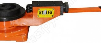
The abrasive cutting machine is designed for cutting metal reinforcement, rods, profiles, I-beams, pipes of different diameters, solid parts and profiles at different angles. Works with an abrasive wheel.
A band cutting machine or band saw operates on the principle of a closed metal strip moving on pulleys.
At home, the easiest way is to build a cutting disc machine for metal. There are several ways to make a cutting machine with your own hands, but the simplest method will be the most understandable.
The manufacturing process of a machine based on a cutting disc
To work you will need:
- steel corner,
- channel,
- drill,
- welding machine,
- electric motor,
- bearing pair,
- starting circuit,
- switch,
- shaft,
- coil,
- wooden board or steel sheet for the working surface,
- box to ensure the operation of the electrical circuit.
1. After preparing all the tools, make a frame or a general frame of suitable dimensions, for example, from angle No. 25. The parts of the structure are measured according to the drawing on a cutting machine and cut with a grinder, then welding begins. The finished frame can be placed on vibration-supported legs, which will facilitate the operation of the machine. It is easier to make the legs from the same profile or small diameter tubes.
2. Channel No. 10 is welded to the resulting table, which acts as a guide axis; it will become the basis of the structure for attaching the cutting part of the machine and connecting it to the motor. Next, the main parts are attached to the channel, including two vertical posts secured with bolts.
3. Next, you need to weld another frame from the profiles - this is the base for mounting the electric motor and the main cutting disk. On the other side of the frame, an electric motor with a power of about 1.5-2 kW is fixed. Asynchronous motors are considered the most durable and reliable. The motor will need to be powered from a 3-phase network. We remind you that a higher power engine will provide a more even cut and good speed of metal cutting work.
4. The method of fastening the shaft and the general principle of its connection to the structure are not important. A threading machine, when properly ensuring the supply of revolutions from the electric motor to the rotating shaft, must work reliably. The V-belt will help provide this. Some work can be ordered from a turner (shaft with supports, belt pulley and disk flanges). It is advisable to make the flange projection with a diameter of 32 mm.
5. Next, the support bearings are mounted in the sockets of the upper frame plates on the channel. Bolts and nuts can be used to secure the motor and shaft. Ensuring the operation of the electrical circuit is in a ready-made box with a switch, which is attached to the bottom of the frame.
6. The connection of the racks with a shaft with a diameter of 12 mm is made using a sleeve. To prevent it from slipping, the sleeve and shaft are connected with the smallest gap during a sliding fit. A rocker arm from the channel is welded onto the bushing so that its arm is in a ratio of 1:3.
7. You will need to install a rigid spring near the engine - to ensure return, it will even work from an expander. The springs and chains should be securely secured with bolts.
8. The electric motor is installed on the side of the smaller section of the rocker arm, and the shaft on the larger side. A belt drive will ensure the movement of the shaft.
9. An emergency stop button and a starting circuit are required, while the engine must be connected through a box and a three-pole circuit breaker, and the stop button leads to a direct connection to the network. Connecting the machine will be provided by a three-pole starter that starts the electric motor.
10. Be aware of the sparks that will fly from the disk - provide it with a casing. The work is first checked at idle, and only after making sure that the design is reliable, you can try cutting soft metal, for example, aluminum, in order to correct all inaccuracies. The working surface of the structure can be made of metal or wood and covered with thick plywood; if necessary for work, secure it with a vice.
The manufacturing process of a machine based on a grinder
There are several ways to make a metal cutting machine with your own hands - there are several good videos on this topic.
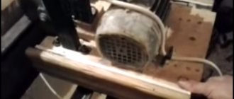
First way. The simplest device is a frame made of pipe, which will also serve as a comfortable handle. On one side, a transverse strip is attached by welding, on which there should be holes for attaching an angle grinder. The movable shaft will be attached to this base on a piece of angle, the same part can be attached to the floor of the garage or to the desktop. And on the other hand, it is attached to a spring, with the help of which the machine structure can return to its original position. If you attach the grinder correctly, the device will help you cut metal more accurately, freeing up one hand.
Don’t forget about the back impact of the grinder, when the tool is thrown back if the abrasive disc jams. And abrasive fragments from disc destruction can cause serious injury. An angle grinder attached to the machine with a closed casing minimizes such consequences. However, the simplest design does not allow for high-precision cutting, for example, when you need to cut small pieces of steel rod that require further adjustment.
The second way to transform an angle grinder into a cutting machine for metal work. This machine can be made collapsible.
To work you will need:
- welding machine,
- drill,
- steel corner,
- profiled pipe,
- channel,
- shaft,
- spring,
- relay,
- identical bearings,
- pedal,
- bolts,
- wooden board or steel sheet for the work surface.
1. A preliminary drawing or sketch is required, which indicates all the dimensions and necessary details. Ready-made drawings for a metal cutting machine are available on the Internet, but you will still have to make your own adjustments using what is already available on the farm. An easy sketch does not require precise measurements; it is enough to observe the proportions and have an accurate idea of each structural element. And remember that you will have to change the frame to accommodate different sizes of the grinder’s working disk.
2. Two frames on a common axis are the basis of the simplest machine frame, and it is better to weld them from metal. On the lower part it is necessary to weld the fastening, which will consist of a movable clamp and a clamping angle. The part on which the angle grinder will be attached must be made to move vertically relative to the bottom, like a pendulum. You cannot do without a spring; it is needed to return to the starting position. Additionally, weld a ruler with a limiter for accurate measurements.
3. The start of operation of such a machine will be ensured by a start pedal (button), connected through a low-voltage relay, supplying voltage to the angle grinder. After switching on, the design must be checked at idle speed. If the circle does not touch the casing and rotates freely, then you can use the design in practice - a homemade machine for cutting metal is ready.
4. This design can be collapsible, and other removable disks can be installed on the grinder. When working with other materials, be aware of the characteristics of the materials when cutting them. Remember safety precautions and precautions when performing metal work.