Definition of anchor bolts
Foundation Anchor Bolts
The bolt is held in the foundation by friction and thrust force. The expansion is created by the expansion of a steel collet or a plastic dowel. The pressure (thrust) received by the anchor arises in depth and is compensated by the internal obstruction of the material due to bending, compression, and crushing. This principle is typical for metal anchors and foundation bolts.
The hardware is destroyed at the weakest point, and this happens:
- explosion of a hardware product - absolute or partial release while maintaining the integrity of the structure;
- shear - destruction along the boundary of the base under the influence of shear;
- fracture or bend - deformation under the influence of bending force;
- foundation explosion - destruction under a load that is higher than the bearing capacity of the foundation.
Corrosion may develop after installing anchors on its individual parts. Hardware is destroyed by high temperature and burns out.
Main types of products
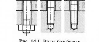
The product has various design features, in addition to threads on one edge. The end of the anchor can be curved or straight.
There are varieties:
- curved with two nuts and a washer;
- foundation bolt with anchor plate;
- composite section anchor;
- removable view;
- straight type with two nuts and washers;
- with a conical end.
By size they are divided into small (length up to 55 mm, and cross-sectional perimeter up to 8 mm), medium (up to 120 and 12 mm, respectively), large (220 and 24 mm). According to the installation option, there are spacer, wedge and driven ones.
Curved
The variety has a hook ending instead of a threaded section. Products are produced up to 180 mm and are installed in reinforced concrete bases. The hook provides comfort when hanging objects on a vertical fence.
Under the hook there is a nut, which is used in the design of curved hardware and serves to expand the spacer collet. This way the sleeve is securely fixed in the partition or load-bearing wall. The convenience of this type is that it can be removed at any time if necessary.
These types are used in everyday life and are used for hanging lighting devices, boilers, and other devices. In other versions, the free end is bent into a ring and is adapted to tension the rope.
Composite
The fastener consists of an anchor plate and a rod, which is connected by a coupling to a pin. A stud can be secured in concrete using a thread onto which a nut is screwed to tighten large building components or pieces of equipment. The hairpins reach several meters in length.
The foundation combination bolt is used to secure the equipment in the support. The lower rod of the fastening element with the anchor plate and coupling is placed before the concrete is supplied, and the upper part is screwed into the clutch. The hardware is screwed onto the stud, then the top is welded. The thread type used is metric and the material is structural carbon, low alloy or structural steel.
Removable
The anchor end is embedded monolithically in brick or concrete, and a bolt is screwed into it, which can be removed from the hole if necessary. Expansion anchors are used in finishing and repair work and consist of a wedge and an expansion collet. The efficiency of the work depends on the type of embedding material and the depth of anchoring of the foundation bolts.
The sleeve expands with a wedge and is firmly held in the concrete due to friction forces. During installation, the wedge can be driven inside the collet or screwed into the thread. There is a type of fastener when the sleeve is equipped with two expansion areas and blocks the release of hardware near the head and on the body of the anchor device. These varieties are used to fasten the filling of potholes, partitions, and supporting profiles for panel finishing.
Direct
They look like metal pins with a thread on one end. They are mounted in monolithic areas simultaneously with laying concrete or glued into the finished base. According to the standards, straight anchors should not exceed 140 cm.
Drive-in anchors are mechanical varieties and consist of two elements:
- steel frame or other durable material;
- a threaded pin that screws into the cassette.
Straight hardware is used in construction; they fasten objects of various sizes, lightweight structures, fix communications, household appliances and industrial equipment. Direct anchors are not installed in weak concrete or brick with cracks or other minimal damage.
With anchor plate
The bolts are produced in the form of a rod with a metric thread, on one side of which the plate is secured using washers and nuts. The supporting element is designed for strong fixation in concrete. Such fasteners are produced up to 5 m in length and are made from high-strength steel grades 09G2s, 20, 40X, 35.
Before attaching the anchor to the base, a special glue or chemical solution is poured into the hole. With such fasteners, it is important to follow the application and curing technology, otherwise the load-bearing capacity of the connection may be affected. The operating time of each type after pouring the glue is indicated in the instructions. The anchor plate increases the support area of the object and provides additional support.
Foundation bolts. Design guidelines
3.3. Foundation bolts for fastening building structures must be designed in accordance with SNiP 2.09.03-85. Bolt designs must be made in accordance with GOST 24379.0-80 and GOST 24379.1-80. 3.4. According to the design solution, the bolts can be bent, with an anchor plate, straight or conical (Table 1).
Table 1
| Bolts | With a bend | With anchor plate | Direct | Conical |
| Diameter (thread) d, mm | 12-48 | 12-90 | 12-48 | 12-48 |
| Sketch | ||||
| Embedment depth H | 25d | 15d | 10d | 10d |
| Distance between bolt axes C | 6d | 8d | 5d | 10d |
| Distance from bolt axis to edge l | 4d | 6d | 5d | 10d |
3.5. According to the installation method, bolts are divided into those installed before concreting the foundations into which they are embedded (with a bend and with an anchor plate), and those installed on finished foundations in wells or wells (straight, curved and conical). 3.6. According to operating conditions, bolts are divided into design and structural: design bolts include bolts that absorb loads arising during the operation of building structures; Structural bolts include bolts intended for fastening building structures, the stability of which against overturning or shifting is ensured by the structure’s own weight. 3.7. Bolts with a bend and an anchor plate can be used for fastening building structures without restrictions. Bolts installed in wells should not be used for fastening load-bearing columns of buildings and structures equipped with overhead cranes, as well as for high-rise buildings and structures for which wind load is the main one. 3.8. The steel grade of design bolts operated at a design winter outside air temperature of up to minus 65o C inclusive should be assigned according to Table. 2.
table 2
| Estimated winter outside air temperature, оС | Minus 40 °C and above | From minus 40 to minus 50 оС | From minus 51 to minus 65 °C inclusive |
| steel grade | Vst3kp2 according to GOST 380-71 | 09G2S-6 10G2S1-6 according to GOST 19281-73 | 09G2S-8 10G2S1-8 according to GOST 19281-73 |
Note: Bolts can be made from other grades of steel, the mechanical properties of which are not lower than the properties of the steel grades indicated in the table. 3.9. For bolts with a diameter of 56 mm or more at a design winter temperature of minus 40 °C and above, it is allowed to use low-alloy steel grades 09G2S-2 and 10G2S1-2 (GOST 19281-73). 3.10. At a design winter outdoor temperature of up to minus 65 °C, low-alloy steel grades 09G2S-8 and 10G2S1-8 must have an impact strength of at least 30 J/cm2 (3 kgf • m/cm2) at a test temperature of minus 60 °C. 3.11. Structural bolts in all cases (at a design winter temperature of up to minus 65 ° C) are allowed to be made of steel grade Vst3kp2 in accordance with GOST 380-71. 3.12. The minimum depth of embedding bolts in concrete H for concrete class B 12.5 and steel grade Vst3kp2 should be taken according to table. 1. For other steel grades of bolts or classes of concrete, the embedment depth of bolts H□ should be determined using the formula
Н□ □ Н m1 m2 , (85)
where m1 is the ratio of the calculated tensile strength of concrete of class B 12.5 to the calculated resistance of concrete of the accepted class; m2 is the ratio of the calculated tensile strength of the metal of bolts of the accepted steel grade to the calculated resistance of steel grade Vst3kp2. For bolts with a diameter of 24 mm or more installed in wells of finished foundations, the coefficient m1 should be taken equal to 1. 3.13. For structural bolts with bends, the depth of embedment in concrete can be taken equal to 15 d, for bolts with anchor plates - 10 d, for bolts installed in wells - 5 d. The minimum permissible distances between the axes of bolts C and from the axis of the outer bolts to the edges of the foundation l are given in table. 1. The distances between the bolts, as well as from the axis of the bolts to the edge of the foundation, can be reduced by 2d with a corresponding increase in the embedment depth by 5d. In addition, the distance from the axis of the bolt to the edge of the foundation can be reduced by one diameter if there is reinforcement of the vertical edge of the foundation at the location where the bolt is installed. In all cases, the distance from the axis of the bolt to the edge of the foundation should not be more than, mm: 100 for bolts with a diameter of up to 30 mm inclusive 150 " " 48 " 200 " " St. 48 « 3.14. Depending on the method of installation of steel columns, the elevation of the top of the foundation and additional requirements for its construction are determined. When installing steel columns without alignment, having a milled end and a planed shoe slab, a grout device under the shoe slab with a thickness of 50-70 mm is required, which determines the level of the top of the foundation. When installing steel columns with a shoe in the form of a plate welded to the column rod, the column is aligned; for this, the anchor bolts must have additional nuts and washers located under the shoe base plate, on which the column is installed during installation. With this method of installing steel columns, a grout device under the shoe slab with a thickness of 100-150 mm is required; the anchor bolts are equipped with nuts and washers located above and below the shoe plate. Installation of steel columns with lightweight alignment ensures accurate installation of columns while reducing the complexity of their manufacture. 3.15. Installation of anchor bolts during the construction of foundations requires special conductors. It is recommended that anchor bolts be combined into rigid blocks, the installation of which is strictly fixed when concreting the foundations.
Calculation of anchor bolts
When calculating the type and size of fasteners, take into account the material into which the anchor needs to be screwed and the magnitude of the load on the hardware. Simple hardware can withstand 230–500 kg, while chemically strengthened hardware can withstand 700 kg.
The calculation of foundation bolts takes into account the following factors:
- dynamic characteristics that depend on the direction of application of force;
- static pressure does not change and is taken according to calculated indicators from the tables.
Manufacturers indicate strength when packing, but designers calculate load-bearing characteristics for shear and tear, and at the same time make a standard safety margin by applying appropriate coefficients.
For group installation
The load is calculated for the bolt that experiences the most negative force.
Calculation of anchors to find the design pressure is carried out according to the formula P = -N / n + M y1 / Σyt², where:
- N—design force;
- M is the expected bending moment;
- y1 is the length from the rotary axis to the most distant hardware;
- n is the number of anchors;
- yt is the length from the rotary axis to the 1st bolt (pressed and tensioned fasteners are taken into account).
The axis of circulation is assumed to pass through the center of gravity of the load-bearing area of the equipment. For through metal columns, steel vertical elements of solid section, similar expressions are used to find the tensile load. The parameters of the type of concrete, the dimensions of the main surface, and the size of the compressed area under the column are entered.
Determining the pre-tension value
Calculation table of embedment depth, distances between axes, tightening coefficient
Bolts are tightened to a certain degree of tightening F, the value of which for static pressure is taken to be 0.75 P, and for dynamic loads 1.1 P is used, where P means the calculated pressure on the fastener. Tightening of construction hardware is done manually using devices with force to the absolute stop.
The cross-section of the rods is checked for strength under dynamic influence before installing the anchor according to the formula Ai = 1.8 g n k P / a R, where:
- g is the pressure coefficient from the table;
- n — scaling factor, selected from the table;
- a is an indicator of the number of load supply series;
- R is the design tensile strength of the alloy (anchor material);
- ko - coefficient according to the table.
The cross-sectional area of the rod is found from the reliability conditions for dynamics and statics. The coefficient ko is taken to be 1.05 or 1.15.
Distance from the edge of the foundation to the anchor bolt
The diameter of anchor bolts for the above steel grades is 12, 16, 20, 24, 30, 36, 42, 48, 56, 64, 72, 80, 90, , , and mm. Based on the experience of designing buildings and structures, when the column is hinged to the foundation, anchor bolts with a diameter of at least 20 mm are used, and for a rigid connection - at least 24 mm.
For design bolts made of low-alloy steel and foundation concrete with a compressive strength class of more than B 12.5, the tabulated values l an are multiplied by two coefficients k 1 and k 2:. To secure the base of centrally compressed columns, anchor bolts are installed structurally. To fasten the base of eccentrically compressed columns, anchor bolts are installed according to calculations.
Crap. 129. The shortest distances between anchors and from anchors to the edge of concrete
In this case, a combination of external loads is used, at which the bending moment is the greatest and the longitudinal compressive force is the least. In this case, the design forces in the stretched anchor bolts are determined from the condition of their joint work with the compressed concrete of the foundation edge.
The calculation is carried out as for rectangular sections of eccentrically compressed reinforced concrete elements.
This is the condition for the equality of the moments of external forces and internal forces relative to the axis of the stretched bolts. From this equation the height of the compressed zone of concrete x: is determined.
Calculation schemes for determining the forces in anchor bolts of steel columns: a - continuous type, b - through type. Here, the branches of the columns work on longitudinal axial forces, and the magnitude of the design force P per one bolt of the stretched branch is determined from the condition of equality of the moments of external forces and internal forces relative to the axis of the compressed branch:.
Next, determine the required bolt diameter using the appropriate tables or formula. Composite bolts with anchor plates, see. In these cases, the coupling and the lower pin with the anchor plate are installed in the foundation mass during concreting, and the upper pin is screwed into the coupling for the entire length of the thread after installing the equipment through the holes in the supporting parts.
The length of screwing the stud into the coupling must be at least 1.6 times the diameter of the bolt thread. Bolts, curved and with an anchor plate, are installed before concreting the foundations on special conductor devices that strictly fix their design position during the concreting process. Removable bolts, see. When installing removable bolts in the foundation mass, only anchor reinforcement (anchoring devices) is laid, and the stud is installed freely in the pipe after the foundation is installed.
Curved bolts installed in the “wells” of ready-made foundations, see Straight bolts on synthetic epoxy or siloxane adhesives and secured using a cement-sand mixture using the vibration caulking method, see Expansion-type bolts, secured using an expanding collet, see Bolts with a conical end, secured with cement - sand mortar using the vibration immersion method, see Bolts installed in drilled holes in finished foundations are not allowed to be used for fastening load-bearing columns of buildings equipped with overhead cranes, as well as for high-rise buildings and structures for which wind load is the main one.
To fasten these structures, it is allowed to use bolts with a conical end, installed by vibration immersion. In this case, the depth of embedding of bolts must be at least 20 d.
Crap. 129. The shortest distances between anchors and from anchors to the edge of concrete,
For measures to ensure the reliability and durability of anchoring, increased embedment depth, additional anchoring devices, etc. To fasten technological equipment, it is allowed to install bolts with a diameter of over 48 mm in wells with an appropriate feasibility study and in the presence of drilling equipment.
Expansion dowels are intended for securing mainly plumbing, electrical and ventilation equipment, as well as finishing elements, cladding, etc. The designs and dimensions of expansion dowels are given in the appendix. Dowels are intended for structural fastening of various small equipment, as well as metal structures, decorative trim parts and other elements on foundations, walls and other building structures made of concrete, reinforced concrete and brick.
Anchor bolts. Minimum distance from the edge of the column
Technical documentation for dowels was developed by VNIImontazhspetsstroy. Fastening units with bolts with an expanding collet and expansion dowels can be put into operation immediately after installing the bolts and dowels. Loads acting on bolts are divided into static and dynamic according to the nature of the impact. The magnitude, direction and nature of the operating loads from the equipment on the bolts must be indicated in the assignment for designing foundations for the equipment.
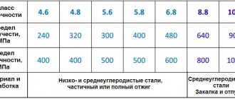
Bolts may be made from other grades of steel, the mechanical properties of which are not lower than the properties of steel grades indicated in Table. For bolts with a diameter of 56 mm or more, it is permissible to use low-alloy steel of grades 09G2S-2 and 10G2S GOST under the same temperature conditions. The calculated tensile strength of bolt metal Rva should be taken according to the table. Calculated tensile strength of the metal Rva, MPa.
For building structures, steel columns of buildings, etc. The cross-sectional area of threaded bolts should be determined from the strength condition using the formula.
The depth of the foundation h gf, its total height hf, the decision on the number of steps of the slab part, their total height h pl and the height of the column support h cf, if any, are taken in the same way as for foundations for reinforced concrete columns.
When a column is hinged to the foundation, anchor bolts are installed structurally to fix the design position of the column and secure it during the installation process. In this case, the anchors are attached directly to the base plate of the column.
With rigid coupling, the anchors are attached to the column rod using special remote console tables, and in fact they are installed in the foundations behind the dimensions of the base plates.
For removable bolts with anchor plates installed freely in a pipe, the coefficient k o for dynamic loads is taken equal to 1. Under the action of dynamic loads, the cross-section of the bolts, calculated by formula 1, should be checked for endurance using the formula. Bolt designs. Conical spacers. Bolt thread diameter d, mm.
The choice of steel grades for plates of embedded parts is made according to table. The thickness of plates or other external elements of embedded parts is determined in accordance with clause. In addition, when welding steel elements to a plate in contact with concrete, its thickness should be taken, depending on the height of the installation fillet weld, no less than the values indicated in table. When assigning plate dimensions close to the cross-sectional dimensions of a reinforced concrete element, their permissible positive deviations provided for by regulatory documents should be taken into account, and it should be possible to freely install the embedded part with minus deviations in the form dimensions.
When calculating fastenings of building structures, the pre-tightening force and cross-sectional area of the bolts should be determined as for static loads, unless there are special instructions in the project. When installing bolts for fastening equipment in a group, Fig.
Calculation scheme for determining forces during group installation of bolts for fastening technological equipment. The axis of rotation may be taken to pass through the center of gravity of the supporting surface of the equipment. For through steel columns with separate bases, the value of the calculated tensile load per bolt should be determined by the formula.
For bases of solid steel columns, Fig. According to the design solution, the bolts can be with a bend, with an anchor plate, straight or conical spacer tables. According to the installation method, bolts are divided into elements installed before concreting, into which they are embedded with a bend and an anchor plate, and into ready-made elements installed in straight and conical holes drilled.
Straight bolts in wells are secured using synthetic glue or vibration caulking, and conical bolts are secured using expanding collets or cement-sand mixtures. According to operating conditions, bolts are divided into design and structural. Design bolts include bolts that carry loads arising during the operation of building structures or equipment operation. Structural bolts include bolts intended for fastening building structures and equipment, the stability of which against overturning or shifting is ensured by the own weight of the structure or equipment.
Gap from bolt to foundation cut
If the depth of the bolt increases by 5 diameters, the distance between the anchors can be shortened by 2 diameters. The gap from the center of the bolt to the foundation cut can be reduced by another 1 diameter if there is vertical reinforcement of the edge of the base in the area where the fasteners are installed.
In any case, the span from the center of the head to the edge of the base is taken as follows:
- not less than 100 mm for hardware with a diameter of up to 30 mm;
- 150 mm - for anchors with a diameter of 48 mm;
- 200 mm - for fasteners with a diameter greater than 48 mm.
If paired bolts are installed, a single anchor plate is used for them with a gap between the holes taken according to calculations.
Loads and dimensions
6.1. Applied Loads
Recommended loads
The recommended loads on the anchor, which are “prescribed” in its certificate, are established based on the results of thorough certification tests. Recommended loads usually already include reducing safety factors.
Load direction
It is clear that the loads applied to the anchor should be less than those recommended by its manufacturer for a given direction - tension and shear. However, with combined loading, it is necessary to ensure that not only the tensile and shear components of the load do not exceed their recommended limits, but that the resulting load also does not exceed the recommended limits (Figure 4).
Figure 4 - The case when the combined load exceeds the recommended load-bearing capacity of the anchor, and the tensile and shear components of the load remain below their recommended limits [1]
6.2 Distances between anchors and to the edge of the base
There are limits on the distances from the anchors to the edge of the base and the distance between the centers of the anchors. These limitations are shown in Figure 5:
- Ccr is the critical distance from the center of the anchor to the edge of the base, at which the anchor is still working at full strength;
- Scr is the critical distance between the centers of the anchors, at which the anchor is still working at full strength;
- Cmin is the minimum distance from the center of the anchor to the edge of the base at which the anchor can still be used, but with reduced strength characteristics;
- Smin is the minimum distance between the centers of anchors at which they can still be used, but with reduced strength characteristics.
Figure 5 - Zones of influence of anchors and edges of the base [1]
Most anchors comply with this approach, but some displacement-controlled anchors cannot be used at edge distances closer than Ccr due to the high stresses that are introduced into the base material when they are installed.
A common approach when selecting anchors is to apply reduction factors for the distances between the critical and minimum distances, as shown in Figure 6 for the distances between anchors. A similar approach is used for the distances from the center of the anchor to the edge of the base.
Figure 6 - Application of reduction factors for the distance between anchors [1]
6.3. Increased anchor depth
Recommended loads for most fastenings refer to the maximum thickness of the bracket, which corresponds to the minimum depth of the anchor. In many cases, with increasing depth of the anchor, its technical characteristics increase with a change in the form of its failure, for example, from puncturing a concrete cone to breaking steel (Figure 7).
Figure 7 - The deeper the anchor, the greater its load-bearing capacity [1]
6.4. Static and dynamic loads
Recommended anchor loads usually apply to static loads only. If the loads are dynamic, then additional measures must be provided.
When the bracket is secured by tightening the fastener to the specified torque recommended by its manufacturer, the resulting clamping force must exceed the recommended anchor load limit by a significant amount. The maximum value of dynamic loads should be lower than the recommended load for the anchor and, therefore, lower than the clamping force of the bracket (Figure 8).
Figure 8 - Relationship between dynamic and recommended loads [1]
For shock loads, the anchor manufacturer should be consulted.
Anchoring depth
If the height of the base allows the bolt to be fully screwed in, the holes are drilled to the design size and, after installation, sealed with a mixture of cement and sand. If the size of the foundation does not allow the anchor to be completely buried, replace it with a bolt with a bend and a cone-shaped spacer collet.
If the project requires a bolt with a size 3 times smaller than the mounted fasteners, the product is placed in concrete to the required depth. In this case, the condition is met that the hardware functions with absolute design resistance. You can reduce the installation depth of anchor bolts in proportion to the force affecting the fastener.
Bolt installation principle
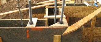
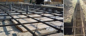
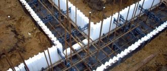
The installation of anchor elements begins after laying the reinforcement cage inside the formwork. In other words, when the preparation before concreting is completed.
The pins are fixed for welding or with a knitting wire, depending on how the reinforcement for reinforced concrete pouring was knitted.
Fasteners must not be installed deeper than the foundation level; anchors with visible defects or damage must not be used without first checking their functionality. The installation depth must be observed, otherwise the bolt will go inside the loose soil, where it will dangle and will not secure anything.
The process is not the most complicated and can be done independently.
It is necessary to strictly follow the approved house plan in order to correctly arrange the elements at the intended placement points of different structures. It is necessary to take into account the locations of doorways where bolts are not installed inside. The foundation anchor is placed only under the walls of the planned house.
Schematic illustration of installation
When the cement-sand mixture is poured into the formwork, a connector is inserted inside it. You will need to carefully monitor the depth of the anchor.
The anchor connections are not placed too tightly to each other, maintaining the distance. Usually, between two fastening points, at least two depths of anchors are left inside the foundation.
When the part is placed at the desired point, make vertical adjustments and leave the solution to dry. When the hardening process is completely completed, the parts protruding above the foundation are fastened with metal plates or wooden boards.
If the device is inserted into dry concrete, first drill a place for installation, which will be much larger than the diameter of the anchor, but not deeper than the thickness of the poured foundation.
According to regulatory documents, an adhesive solution or a mixture of cement and sand is prepared, and the finished mixture is poured into the hole. A connector is inserted inside the concreted hole, aligned vertically, and left until dry.
General recommendations for the calculation of anchor bolts
If the base heats up above +50°C, the effect of temperature on the anchor material is taken into account when performing the calculation. Take into account the effect of heat on adhesives or chemical fastening solutions. Hardware that works in an aggressive environment is accepted into the development of a project with increased requirements.
Removable bolts are used for fastening conveyors, electrical and other heavy equipment, and curved bolts are designed for concrete wells of hardened foundations. Straight products with epoxy glue are laid to secure the ceiling and equipment.
Installation rules
The surface of the working part of the anchor is cleaned mechanically before installation, rust, dust, and grease are removed. Fat is removed by roasting followed by rubbing with alcohol or acetone. Addressable vibrators operate with a voltage of 36 V.
The bolts are placed in the hole after mixing the sealing mortar and preparing the hole. The fastener is placed in the hole, and a little mixture is supplied between the wall of the hole and the hardware. A vibration seal is placed on the rod, and the solution is poured into the dispensing compartment. During installation, the vibration compactor rotates 20–30°.
