Main Magnetic Particle Testing Procedures
- Preparation. It is necessary to study the technological map, select indicator materials and equipment, and ensure proper metrological support. Determine the scheme and method of magnetization, type and magnitude of current.
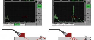
- Magnetization. To detect surface defects, alternating or pulsed current is required. Direct and rectified current is effective for both surface and subsurface layers (at a depth of 2 mm). To prevent local heating and burn-through, it is recommended to carry out magnetization in intermittent mode. For this stage of magnetic particle testing, control samples (disks, rods, plates, pins and other workpieces) are used. With their help, it is much easier to select the exact value of the magnetizing current.
- Application of the indicator. It should cover the entire area under study, including hard-to-reach niches, blind holes, grooves, etc. When using aerosol cans, ensure that the distance between the nozzle and the surface is 200–300 mm.
- Inspection. This stage of magnetic particle testing is performed after the excess indicator has drained off. Identified discontinuities are carefully examined using optical instruments and instruments. In stationary installations, automated systems for deciphering indicator patterns are used. When performing manual flaw detection, the length and coordinates of discontinuities are measured with rulers, squares and calipers made of non-magnetic materials. The type of defect can be determined by the nature of the indicator trace. Thin elongated lines indicate planar defects, rounded patterns indicate volumetric pores, inclusions and cavities. If the powder deposition does not have clear contours, this serves as an indirect sign of subsurface discontinuities. Depending on the sensitivity requirements, combined lighting of the work area is selected using discharge and halogen lamps. To protect against glare, luminaires with diffusers and reflectors are preferred. The ability to adjust the lighting intensity is required. When working with luminescent indicators, ultraviolet radiation sources of 2000 μW/sq.m. are used. cm and above with a wavelength of 315–400 nm.
- Registration of magnetic particle testing results. First of all, they make the appropriate entries in the journal, act, route map, protocol, etc. Defectograms can be attached to the description and schematic image - a photo and video recording of an indicator pattern. Files can be transferred to a PC and duplicated on a USB drive. If the instructions require it, markings are applied to suitable areas and identified defects - directly on the surface of the object.
- Demagnetization. Residual magnetization must be removed, as it can cause the accumulation of wear products, interfere with the correct operation of electrical equipment and negatively affect the subsequent processing of the product.
Types of magnetization
With the magnetic particle testing method, types of magnetization that are applicable to parts of simple shape are more often used:
- circular creates a uniform magnetic field inside the part, there are no magnetic poles at the ends;
- longitudinal is called pole: a plus is formed at one end of the workpiece, a minus at the other, the field is directed along the part;
- combined involves the simultaneous influence of several multidirectional magnetic fields (in two mutually perpendicular directions, three or more).
In production, a type of magnetization of welds in a rotating magnetic field is used.
Various types of electric currents are used for magnetization:
- constant creates uniform induction;
- variable is applicable for less sensitive control methods;
- Pulse characteristics are close to constant.
Single-cycle and rectified current generators are built into flaw detection devices.
Other methods of acoustic flaw detection:
— An acoustic emission flaw detector is based on the reception and analysis of acoustic emission waves that arise in a product when cracks develop during loading. — A velocimetric flaw detector is based on measuring changes in the speed of propagation of elastic waves in the area where defects are located in multilayer structures, and is used to detect areas of adhesion between metal layers. — An acoustic-topographic flaw detector is based on excitation of powerful bending vibrations of a given (in the first version of the method) or continuously changing (in the second version) frequency in the controlled product with simultaneous visualization of the vibration pattern of the surface of the product, for example. by applying a fine powder to this surface. With sufficiently strong vibrations of the surface of the product with a given frequency, powder particles from places that do not belong to the nodes gradually shift to the vibration nodes, drawing a picture of the distribution of nodal lines on the surface. For a defect-free isotropic material, this picture is clear and continuous. In the defect zone, the picture changes: nodal lines are distorted in the place where inclusions are present, as well as in areas characterized by mechanical anisotropy. properties, or are interrupted in the presence of delamination. If the second version of the method is used, then in the presence of delamination, the section of the upper layer of the product located above it is considered as an oscillating diaphragm fixed at the edge; at the moment of resonance, the amplitude of its oscillations increases sharply, and the powder particles move to the boundaries of the defective zone, outlining it with great accuracy. The flaw detector operates at frequencies of 30–200 kHz. The sensitivity of the method is very high: in a multilayer product with a top sheet thickness of 0.25 mm, defects with a length of 1-1.5 mm are detected. There is no dead zone, scanning is not required - the emitter is pressed against the surface of the product at one point.
What methods of checking welded joints are used
The methods are divided into two groups:
- Non-destructive testing (hereinafter referred to as NDT).
- Destructive testing methods.
Of the second group, mechanical tests are most often used.
In industrial use, transport, construction and the national economy, non-destructive methods have become recognized and widespread. The development of measurement technologies occurs precisely in this area of control. Let's look at the NDT methods in more detail.
- Visual and measuring control. This is the initial way to check the quality of work performed. Includes external inspection of seams and measurement of geometric parameters. For this, simple measuring instruments are used. The obtained figures are checked against the standards in the design documentation, GOSTs, SNiPs and technical specifications. It is used as a primary method for identifying defects and is not able to detect small and hidden intra-suture defects.
- Capillary control. This approach is based on the properties of liquids to penetrate into the smallest cracks, pores, cavities or lack of fusion. Read more about connection defects below in the text. Special penetrating properties are inherent in certain liquids - penetrants. Based on them, compositions are made for application to welds and for magnetic particle testing.
- Ultrasonic testing methods (UT). A universal and universal method for flaw detection of welded joints. Analysis of indicators and detection of cracks is carried out using flaw detectors, which consist of ultrasound emitters and receivers. There are echo-pulse, echo-mirror and mirror-shadow methods of ultrasonic testing.
- TOFD or time-of-flight diffraction testing. More often used for research and detection of defects in circumferential and longitudinal welds using ultrasonic echo. The action is based on the difference in reflected waves from a crack or from a fully welded surface. Both the single-group TOFD method and methods with multi-support of several groups or techniques with a combination of other control methods, for example with pulsed or echo-surface waves, are used.
- Eddy current analysis. It is carried out using certified instruments - vortex flaw detectors. Based on identifying problems in test welds by comparing changes in eddy current and electromagnetic fields. Its operation is similar to ultrasonic testing methods. Like the magnetic particle method, it is used to test depths up to 2 mm.
- Radiation flaw detection of welded joints. In practice, it is also called x-ray testing, because the research is carried out using x-ray gamma radiation. This is the most effective method of control, but it has very limited use due to radiation hazards and the mandatory use of special protective equipment.
- Magnetic particle testing or flaw detection (MPC or MPD). The main character of today's review. Allows you to determine defects in weld metal such as cracks, lack of penetration or lack of fusion, pores and cavities, solid slag inclusions at a depth of no more than 2 mm. In the next section of the article we will talk about regulations and characteristics of weld defects.
Due to the ease of use directly on site, as well as the ability to quickly detect thin and minute cracks, MTD has become widespread. The method does not require expensive and complex equipment or lengthy training of operating personnel. The advantage of this testing option is good visualization of defects. The customer receives clear results without wasting time. Which are visible to representatives of the inspecting and receiving parties. It is important that the results of the study are marked for the welder, who will eliminate the identified deficiencies.
During the verification process, equipment for magnetization and demagnetization corresponding to GOST R 53700-2009 is used. For measurements on non-linear surfaces, such as corners and cylinders, attachments and prisms with different radii are used. They also control the quality of welds on threaded connections, fillets and grooves. And for testing rotating shafts, special prism-cradles are used.
After magnetic particle testing and inspection of the object by flaw detectors, they draw up a test report indicating the object and details of the study. The document reflects the date, location, equipment and control methods. The names of the responsible specialists and their expert opinion are recorded.
Magnetic particle inspection method (magnetic particle flaw detection)
As the name suggests, magnetic particle testing is performed using magnetic powder. There are two methods of magnetic particle testing: dry and wet.
In the case of dry magnetic particle flaw detection, dry magnetic powder (iron filings, scale, etc.) is applied to the surface of the welded joint. In the case of wet magnetic particle flaw detection, magnetic material is applied in the form of suspensions of magnetic powder with kerosene, oil, and soap solution.
Under the influence of electromagnetic stray fields, powder particles move evenly over the surface of the welded joint. Above the weld defects, magnetic powder accumulates in the form of rollers. Based on the shape and size of these rollers, one can judge the shape and size of the defect found.
Magnetic particle testing technology
The magnetic particle flaw detection method includes the following technological operations:
1. Preparing the surface of the welded joint for inspection. Surfaces must be cleaned of dirt, scale, welding spatter, sagging and slag after welding. 2. Preparation of the suspension, which consists of dynamic mixing of the magnetic powder with the transported liquid 3. Magnetization of the controlled product 4. Applying the suspension or magnetic powder to the controlled surface 5. Inspection of the controlled surface of the welded joint and identification of areas where powder deposits are present 6. Demagnetization of the welded joint .
The effectiveness of magnetic particle flaw detection
The magnetic particle flaw detection method has good sensitivity to thin and minute weld cracks. It is easy to implement, gives clear results, and does not take time.
The sensitivity of the magnetic particle method may vary in each individual case. This depends on the following reasons:
1. The size of the powder particles and the method of its application 2. The magnetic field voltage acting on the welded joint 3. The type of current used (alternating or direct) 4. The shape and size of the defect, the depth of its location, as well as how the defect oriented in space. 5. On the method and direction of magnetization of the connection 6. On the quality and shape of the controlled surface
Using magnetic testing methods, planar defects are best detected: welding cracks, lack of fusion and lack of penetration, if their largest dimension is oriented at a right angle (or close to a right angle) relative to the direction of the magnetic flux.
Round-shaped defects (pores, cavities, non-metallic inclusions) may not create sufficient diffuse flow and are the worst to detect during inspection.
Flaw detectors for magnetic particle testing
Flaw detectors for this testing method include current sources, devices for supplying current to the test surface, devices for magnetizing the surface (solenoids, electromagnets), devices for applying magnetic powder or suspension to the surface being tested, and current (or magnetic field strength) meters.
Magnetic particle flaw detectors are divided into stationary, mobile and portable. Stationary flaw detectors are widely used in factories and other enterprises with large-scale production of various products. Among them are such models as UMDE-2500, KhMD-10P, MD-5. Such equipment allows you to control the quality of welded joints of various shapes. They are capable of providing high inspection productivity - from several tens to several hundred products per hour.
Common, mass-produced models of portable and mobile flaw detectors are PMD-70 and MD-50P. Portable flaw detector for magnetic testing PMD-70 is widely used for testing welded joints in the field. A mobile flaw detector model MD-50P is most often used to inspect massive large-sized welded joints in sections.
Video: magnetic particle flaw detection using luminescent concentrates
Non-destructive testing methods
From the point of view of physical phenomena, there are nine main types of non-destructive testing:
- magnetic;
- electric;
- eddy current;
- radio wave;
- thermal;
- optic;
- radiation;
- acoustic;
- penetrating substances.
Magnetic non-destructive testing method
Magnetic NDT methods are used to control parts and products made from ferromagnetic materials that are in a magnetized state. The properties of parts (chemical composition, structure, presence of discontinuities, etc.), which this method allows to control, are associated with the parameters of the magnetization process and the hysteresis loop. Inhomogeneities in the structure of the part, such as cavities, pores, cracks, foreign inclusions, cause changes in the magnetic flux flowing through the part. These inhomogeneities have magnetic properties that differ from the properties of the base material, which leads to a distortion of the magnetic field (Figure 134).
| Figure 134 – Scheme of the formation of a magnetic field above a defect: 1 – part being tested; 2 – crack; 3 – magnetic scattering field; N, S – permanent magnet poles | |
Main types of magnetic NDT methods:
- induction;
- magnetographic;
- magnetoresistive;
- fluxgate;
- magnetic particle.
The most widely used method is the magnetic particle method, which is used to test objects made of ferromagnetic materials with magnetic properties that make it possible to create stray magnetic fields in places of discontinuity that are sufficient to attract magnetic powder particles. The purpose of testing is to detect, by visualizing, the nature of distortions of magnetic field lines in the part being tested. Visualization of the inhomogeneity of magnetic field lines is carried out by applying magnetized particles, magnetic powders, both in the form of dry powder and in the form of a suspension, and magnetic films to the surface of the controlled part.
Magnetic particle testing is carried out in accordance with GOST 21105-87 “Non-destructive testing. Magnetic particle method."
Electrical non-destructive testing method
The electrical NDT method is based on recording the parameters of the electric field interacting with the controlled object (electrical method itself), or the field arising in the controlled object as a result of external influence (thermoelectric method). It is used for testing dielectric and conductive materials. Electrical testing methods (electrostatic powder, thermoelectric, electric spark, electric potential, capacitive) allow:
- identify defects in various materials;
- measure the thickness of walls, coatings and layers;
- sort metals by grade, control dielectric or semiconductor materials.
The disadvantages of the listed methods of electrical non-destructive testing are the need for contact with the test object, strict requirements for the cleanliness of the product surface, difficulties in automating the measurement process, and the dependence of measurement results on the state of the environment.
The primary information parameters are electrical capacitance or potential. If a current passes through a controlled part or part area, then the strength and density of the current between a pair of electrodes in contact with the surface is affected by inhomogeneities and discontinuities (Figure 135). This forms the physical basis of the electrical non-destructive testing method.
Figure 135 - Diagram of the effect of a defect on the electric potential: a) in a material without a defect; b) in a sample with a defect
Eddy current non-destructive testing method
The eddy current NDT method is based on the analysis of the interaction of an external electromagnetic field with the electromagnetic field of eddy currents induced in the test object by this field.
The eddy current method is used to detect defects, measure the electrical conductivity of materials, the thickness of coatings - to control structures made of conductive materials. The eddy current NDT method is carried out without contact between the object and the transducer - their interaction occurs at distances that ensure free movement of the transducer relative to the object. This makes it possible to obtain high-quality testing results at high speeds of the objects under study. Cracks, delaminations, sunsets, stains, cavities, non-metallic inclusions, etc. are detected. The method is suitable for detecting defects such as corrosion, wear, erosion, internal cracks, damage and thinning of walls.
The main objects of eddy current testing are electrically conductive rods, pipes, wires, sheets, railway rails, plates, coatings (including multilayer ones), reactor vessels, rollers and bearing balls, fastening parts and other industrial products.
Using eddy current non-destructive testing, discontinuities are detected that come to the surface or lie at a shallow depth, measure exact dimensions, detect vibrations, and determine the physical and mechanical characteristics and condition of objects.
The structural state of metals and alloys affects their electrical and magnetic characteristics, therefore it is possible to control the homogeneity of the chemical composition and structure of metals and alloys, and determine mechanical stresses. On the other hand, this factor may interfere with the detection of cracks and other defects.
Eddy current meters are used to sort metal materials and graphites by grade (by chemical composition). Using eddy current devices, they control the quality of thermal and chemical-thermal treatment of parts, the condition of surface layers after mechanical treatment (grinding, hardening), detect residual mechanical stresses, identify fatigue cracks in metals at the early stages of their development, etc.
Eddy current methods allow solving problems of product size control. These methods measure the diameter of wire, rods and pipes, the thickness of metal sheets and pipe walls with one-sided access to the object, the thickness of electrically conductive (for example, galvanic) and dielectric (for example, paint and varnish) coatings on electrically conductive substrates, the thickness of layers of multilayer structures containing electrically conductive layers. The measured thicknesses can vary from micrometers to tens of millimeters.
Radio wave method of non-destructive testing
Radio wave NDT methods are based on the interaction of an electromagnetic field in the wavelength range from 1 to 100 mm with the test object, conversion of field parameters into electrical signal parameters and transmission to a recording device or information processing means. Based on the nature of interaction with the test object, a distinction is made between transmitted, reflected, scattered radiation and resonant methods. Typically used to test products made from materials where radio waves are not very attenuated: dielectrics (plastics, ceramics, fiberglass), magnetodielectrics (ferrites), semiconductors, thin-walled metal objects. Methods of this type of control allow:
- determine thickness and detect internal and surface defects in products primarily made of non-metallic materials;
- measure the thickness of dielectric coatings on a metal substrate with high accuracy and productivity;
- detect defects that change both the amplitude of the wave and its phase;
- provide sufficiently complete information about the quality of foil dielectric blanks intended for the manufacture of individual layers of multilayer printed circuit boards;
- record changes in the polarization plane of a wave during its interaction with various inhomogeneities.
Thermal non-destructive testing method
The thermal monitoring method is based on remote measurement and recording of temperature fields of the outer surfaces of electrical equipment elements, apparatus and devices that are in operation under operating voltage. The method allows:
- by recalculating the measured temperature differences, assess the condition of the object being examined, identify defects that have arisen in it and determine the degree of their development;
- identify thermally inhomogeneous areas of enclosing structures and, by comparing them with design data, identify the cause of their occurrence;
- inspect objects in the infrared range of the spectrum (“thermal image”), measure the temperature at any point, observe the dynamics of thermal processes, and also create a thermal state data bank for each of the observed objects;
- conduct inspections of boiler houses and thermal stations - identify heat leaks, defects and temperature at any point in the image, obtain thermograms of equipment and pipelines;
- identify defects in brickwork and boiler linings, monitor, test and adjust combustion modes of boilers and furnaces;
- carry out quality control of insulation and tightness of products, identify areas of moisture in the structure;
- carry out tests of building envelopes with different temperature and humidity conditions.
The method is applicable to objects made of any materials. Based on the nature of the interaction of the field with the object of control, methods are distinguished: passive or self-radiation (the object is not affected by an external source of energy) and active (the object is heated or cooled from an external source). The measured information parameter is temperature or heat flow.
Optical non-destructive testing method
Visual inspection is based on observing or recording the parameters of optical radiation interacting with the test object. Visual methods are widely used due to the variety of ways to obtain primary information. The possibility of their use for external control does not depend on the material of the object. Organoleptic visual inspection allows you to detect visible defects, deviations from the specified shape, color, etc.
Visual inspection checks the quality of: preparation and assembly of workpieces, execution of seams during the welding process, finished welded joints. Determine defects in parts and structures visible to the naked eye. Visual inspection is quite informative and is the most efficient NDT method.
Visual inspection is an organoleptic method and serves as a highly effective means for preventing and detecting defects. For example, only after visual inspection and correction of unacceptable defects are welded joints subjected to control by other physical methods (X-ray, ultrasonic, capillary and other types of testing) to identify internal and surface defects.
Visual inspection using optical instruments (lenses, magnifiers, microscopes, endoscopes) is called visual-optical. Using the visual-optical method, all visible damage, marks, cracks, and burrs are identified.
Visual-optical testing, as well as visual inspection, is the most accessible and simple method for detecting surface defects in parts. Optical monitoring tools are used at various stages of manufacturing parts and during routine repair work.
Visual optical instruments include:
- for monitoring small, closely located objects (magnifying glasses, microscopes);
- for monitoring remote objects (telescopes, visual magnifiers, binoculars);
- for monitoring hidden objects (endoscopes, periscopic flaw detectors, mirrors, crawlers, etc.). When working with visual-optical inspection devices, it is necessary to correctly use the visual properties of the flaw detector.
The task of measurement control is to establish compliance with the requirements of regulatory documentation for the numerical value of the controlled parameters. Elements of measurement control can be present in any non-destructive or destructive testing method.
Measurements are carried out using instruments and tools: measuring magnifiers; calipers; metal measuring rulers; probes; goniometers; depth gauges; squares; templates, etc.
When choosing measuring instruments, they are guided by regulatory documents that indicate the required metrological indicators:
- scale division price;
- range and permissible error of measuring instruments;
- measurement limits;
- regulatory conditions of use.
Requirements for optical type control methods are established by GOST 23479-79 “Non-destructive testing. Methods of optical appearance".
Radiation methods of non-destructive testing
Radiation NDT methods are based on registration and analysis of ionizing radiation during its interaction with the controlled product. When passing through a defect and a defect-free area, different absorption of ionizing radiation occurs. The intensity of transmitted radiation will be greater in areas of smaller thickness or lower density, in particular, in places of defects - discontinuities or non-metallic inclusions.
X-ray testing is used to identify rough cracks, burns, undercuts, assess the magnitude of convexity and concavity of the weld root, unacceptable for external inspection, lack of fusion, pores, cavities, slag, oxide and other inclusions in cast and welded steel products up to 80 mm thick and in products from light alloys up to 250 mm thick.
The advantages of the radiation method of non-destructive testing are the clarity of the test results and the ability to identify small round defects (pores), which are not reliably determined by ultrasonic flaw detection.
Radiation testing allows you to detect small defects (individual pores with a diameter of 0.2...0.3 mm).
X-ray testing is the most reliable way to control welded joints and base metal when inspecting pipelines and equipment during industrial safety examinations.
The method cannot fully detect the most dangerous defects - small-opening discontinuities (cracks, lack of penetration) located at an angle of more than 7...120 to the direction of transmission (planar defects). Radiation monitoring does not allow determining the coordinates of defects.
The disadvantages of radiation methods include, first of all, the harm to humans, which requires special radiation safety measures: shielding, increasing the distance from the radiation source and limiting the time the operator stays in the hazardous area.
Radiation equipment has significant weight and dimensions (the weight of the lightest devices reaches 20 kg). Radiation monitoring is expensive - it involves the use of large quantities of radiographic films and means of chemical processing. X-ray inspection devices are characterized by high energy consumption.
Acoustic non-destructive testing method
Acoustic NDT is based on recording the parameters of elastic waves arising or excited in an object. Most often, elastic waves of the ultrasonic range are used (with an oscillation frequency above 20 kHz); this method is called ultrasonic. Elastic waves are used and recorded, the parameters of which are closely related to such properties of materials as elasticity, density, anisotropy (unevenness of properties in directions), etc.
Acoustic methods of non-destructive testing solve the following control and measurement tasks:
- the transmitted radiation method reveals deep-seated defects such as discontinuity, delamination, leaks, and solder gaps;
- the reflected radiation method detects defects such as discontinuity, determines their coordinates, dimensions, orientation by sounding the product and receiving the echo signal reflected from the defect;
- the resonance method is used mainly to measure the thickness of a product (sometimes used to detect zones of corrosion damage, missing solders, delaminations in thin places made of metals);
- The acoustic emission method detects and records only developing cracks or those capable of developing under the influence of mechanical load (qualifies defects not by size, but by the degree of their danger during operation), the method is highly sensitive to the growth of defects - it detects an increase in cracks by 1...10 µm;
- the impedance method is intended for testing adhesive, welded and soldered joints that have thin skin glued or soldered to the stiffeners;
- The free vibration method is used to detect deep defects.
Using metal ringing on impact is an old way of detecting large voids. Steel samples containing voids produce a duller and rougher sound compared to monolithic samples.
Acoustic methods are methods based on the use of elastic waves and vibrations of any frequency. Methods using frequencies from 20 kHz to 100 MHz are called ultrasonic.
The emission and reception of ultrasonic vibrations is carried out by piezoelectric transducers (finders), which are plates made of fine-crystalline (quartz, Rochelle salt) or polycrystalline ceramic materials (barium titanate, lead zirconate titanate).
Acoustic methods of non-destructive testing are divided into two large groups - active and passive methods. Active methods are based on the emission and reception of elastic waves, passive methods are based only on the reception of waves, the source of which is the controlled object itself. Passive acoustic methods are based on the analysis of elastic vibrations of waves arising in the controlled object itself.
A device that implements the ultrasonic testing method - a flaw detector - is designed to detect discontinuities and inhomogeneities in a product, determine their coordinates, sizes and nature by emitting pulses of ultrasonic vibrations, receiving and recording echo signals reflected from inhomogeneities. Figure 136 shows a schematic diagram of a pulsed ultrasonic flaw detector. The radio pulse generator 3 excites the transmitting piezoelectric crystal 1. Ultrasonic vibrations propagate in the controlled part, are reflected from its opposite wall (“bottom signal”) and enter the receiving piezoelectric crystal 2. The reflected ultrasonic vibrations excite vibrations of the receiving piezoelectric crystal 2. In this case, an alternating voltage appears on the edges of the piezoelectric crystal , which is detected and amplified in the amplifier 4, and then goes to the vertical deflection plates of the cathode ray tube (CRT) 5 of the oscilloscope.
Figure 136 – Block diagram of a pulsed ultrasonic flaw detector
At the same time, the horizontal scan generator 6 supplies a sawtooth voltage to the horizontal deflection plates of the CRT 5. The radio pulse generator 3 excites the transmitting piezoelectric crystal 1 with short pulses with long pauses between them. This allows you to clearly distinguish on the CRT 5 screen the signal of the initial (probing) pulse I, the signal from the defect III and the bottom signal II. If there is no defect in the controlled area of the part, pulse III will be absent on the oscilloscope screen. By moving the transmitting and receiving piezocrystals along the surface of the controlled part, defects are detected and their location is determined. One combined piezoelectric crystal is often used to transmit and receive ultrasonic vibrations. The contact points of the piezocrystals to the part being tested are lubricated with a thin layer of oil, gel, or petroleum jelly to ensure continuous acoustic contact with the surface of the part being tested.
Penetrant non-destructive testing method
The capillary NDT method is based on the penetration of indicator liquids (penetrants) into the cavities of surface defects invisible or weakly visible to the naked eye, having the properties of capillaries (cracks, pores, cavities, lack of fusion, intercrystalline corrosion, fistulas, etc.) and recording the resulting indicator traces visually, to determine their location, extent and orientation on the surface.
A necessary condition for identifying defects such as a violation of the continuity of a material by capillary methods is the presence of cavities that are free from contaminants and other substances that have access to the surface of objects and a depth of distribution that significantly exceeds the width of their opening. Requires trained specialists, specialized equipment, auxiliary control equipment, and places special requirements on preparing the surface of the product for inspection.
Testing by the capillary method is carried out in accordance with GOST 18442-80 “Non-destructive testing. Capillary methods. General requirements".
The capillary method is a multi-operational process. A typical list of operations includes preparing the product for inspection, applying an indicator liquid, removing its excess and displaying indicator traces of defects (Figure 137).
Figure 137 – Search for surface defects in metal using the capillary (color) method
Wetting liquids fill narrow cavities of any shape. A necessary condition for this is that the dimensions of the cavities must be so small that the liquid can form a meniscus of continuous curvature, without flat areas. Under the action of capillary forces, wetting liquids fill the cavities of cracks and other surface defects such as discontinuities in the material.
The liquid that has filled the crack cavity will be retained in it by capillary forces even if it is removed from the surface of the part. The manifestation of a crack is carried out using materials wetted by the liquid from the crack. Capillary methods are divided into two types: luminescent and color. In fluorescent flaw detection, defects are detected using luminescent penetrating liquids. Ultraviolet lamps are used for luminescence during testing. A simpler and more often used is the color inspection method, in which defects are identified using brightly colored penetrating liquids.
All non-destructive testing methods are indirect methods. Adjustment (calibration) should be carried out using control samples that simulate the measured physical parameter of the method, which could detect defects of a wide variety of nature. Each individual non-destructive testing method solves a limited range of technical control problems.
Magnetic particle testing methods
- Residual magnetization method (RMM). The main area of application is hard magnetic materials with a coercive force from 9.5 to 10.0 A/cm. By coercive force we mean a value identical to the magnetic field strength sufficient to change the magnetic induction to zero (from the residual induction). Magnetic particle testing using the residual magnetization method begins with the magnetization of the object. Next, the powder or diluted suspension is applied. After the indicator pattern is formed, the surface is inspected and, if necessary, a defectogram is made (for example, using a photo). SON involves passing current in short-term pulses (only 0.0015–2 s). Local overheating of the metal during magnetization does not threaten. The suspension can be applied by watering the surface or immersing it in a bath. Inspection and decoding are easier because the object can be placed in a more convenient position. In general, this is a more versatile and productive way of conducting control.
- Attached field method (AFM). First, indicator powder or liquid is applied before magnetization begins or directly during the process, under the influence of which an indicator trace is formed. Inspection is carried out after and/or during magnetization and drainage of the suspension. Magnetic particle testing using the applied field method is effective for soft magnetic materials, which are characterized by low coercive force (within 10 A/cm). They are generally available for magnetization and demagnetization in a weak magnetic field. However, in a number of cases, SPP is also used for objects made of hard magnetic materials. For example, if the task is to detect subsurface defects at a depth of 0.01–2 mm. Or in the presence of a non-removable non-magnetic coating with a thickness reaching 40–50 microns or more. SPP is also preferred for large-sized objects, when the power of the flaw detector does not allow them to be magnetized to the level required for the residual stress method.
- dry. Powder from metal filings is applied “as is”, without adding any solutions, etc. Powders are made from carefully sifted and crushed iron scale, magnetite, etc. For better visibility, materials can be white, red or yellow. The dry magnetic particle inspection method is suitable for surface and subsurface defects. Magnetization is carried out with direct or alternating current 300–600A using U-shaped electromagnets. To apply indicators, it is convenient to use rubber bulbs, spray guns, moving sieves and other devices;
- wet. Powder particles are suspended in water, liquid soap, kerosene or a special concentrate. It can be applied by brush, dipping, pouring, etc. The wet method is effective for finding surface discontinuities.
Stages of control
Preparing a workpiece or structure for the procedure.
The preparatory process for magnetic particle testing of welded joints consists of cleaning the surface of the element from corrosion, contaminants, as well as lubricants and oils, if the control is performed using an aqueous suspension or dry powder. If the surface of the element is dark in color and the black magnetic powder on it is not noticeable enough, then the element is covered with a layer of a white coloring composition.
Magnetization of the workpiece.
This is one of the priority measures of the magnetic particle method. The sensitivity and determination of deficiencies depends on how correctly the method, direction and type of magnetization, as well as the type of current, are chosen.
3. Applying a magnetic indicator to the surface of the element.
The best solution for applying a suspension is to immerse the element in a container in which the suspension is thoroughly mixed, and gradually remove it from it. But this method is not always advisable. Typically the suspension is applied by hose, spray or shower.
It is important to maintain a low jet pressure, then the magnetic powder remains in defective areas. If the dry magnetic particle testing method is selected, these requirements relate to the pressure of the air stream through which the magnetic powder is applied to the element.
The period of drainage of a dispersed medium of high viscosity takes longer, so the productivity of the controller is reduced.
Visual inspection of the workpiece.
Deciphering the indicator image and performing sorting. The inspector is obliged to inspect the element after the bulk of the suspension has drained from it, when the powder deposits become uniform.
Parts are checked visually, but in some situations professional optics are used to decipher the type of flaws. Its configuration is carried out according to the official documentation.
Who conducts MTD
The IRONCON-Lab construction laboratory carries out magnetic particle testing and radiographic testing of welded joints at competitive prices. Tests are carried out either in a room equipped with special equipment, or at the construction site of the facility. During the examination, a protocol is drawn up in which flaw detectors will make a conclusion about the compliance or non-compliance of the construction work performed.
Application of a magnetic indicator
Indicator material is applied to the previously prepared and magnetized surface. It allows you to identify defects in a part under the influence of an electromagnetic field. It has already been said that powders can be used in this capacity, but some models also work with suspensions
In both cases, before work, it is important to consider the optimal conditions for using the device. For example, the magnetic flaw detector “MD-6” is recommended for use at temperatures from -40 to 50 ° C and at air humidity up to 98%
If conditions meet the operating requirements, then application of the indicator can begin. The powder is applied over the entire area, so that a small coverage of areas not intended for research is also provided. This will allow you to get a more accurate picture of the defect. The suspension is applied by jet using a hose or aerosol. There are also methods for immersing a part in a container with a magnetic indicator mixture. Then you can proceed directly to troubleshooting the product.
Strengths and weaknesses of magnetic particle testing
- Detection of a wide variety of surface and subsurface defects. The method is used to search for grinding, fatigue, stamping, forging, hardening, deformation, etching cracks, hairlines, as well as sunsets, flakes, delaminations, and tears. In welds, MPD is capable of detecting undercuts, lack of penetration, cracks, and the presence of oxide, slag and flux inclusions.
- High sensitivity. The magnetic particle testing method is effective for detecting invisible and weakly visible surface defects with the following parameters: opening - from 0.001 mm, depth - from 0.01 mm and length - from 0.5 mm.
- Possibility of carrying out on objects coated with non-magnetic material (paint and varnish materials, zinc, copper, cadmium, etc.). True, provided that their total thickness is in the range of 40–50 microns;
- Harmlessness. The advantage over the capillary method is that MTD does not require “dirty” indicator liquids - with a smell and a strong coloring effect. The operator's health is not in danger. The facility is clean. There is no need to install additional ventilation hoods in the room.
- the range of possible applications is limited to ferromagnetic alloys. MTD cannot cope if the material is characterized by significant magnetic inhomogeneity. Welds - if they are made using non-magnetic electrodes - are also unsuitable for this method;
- access to the facility is critical for the full implementation of all procedures;
- detectability of defects may decrease. This depends on the parameters of the discontinuities themselves. Thus, MTD is not always able to detect defects whose orientation plane forms an angle of less than 30 degrees - relative to the surface under study or the direction of the magnetic field. Sensitivity also decreases in areas with a roughness of Ra˃10 µm. Normal magnetic particle testing is also hampered by poor cleaning (or lack thereof) of soot, corrosion and slag. Yes: identifying subsurface discontinuities is possible, but one must understand that this task is solved much more effectively by ultrasonic testing and x-rays;
- decryption capabilities are very modest. In essence, MPD is an “indicative” type of NC that allows you to see, rather than measure, defects. It is not intended to determine length, depth, width, or reveal discontinuities.
Magnetic non-destructive testing (flaw detection) of welds and metal
The non-destructive testing laboratory of the Olympus SK carries out magnetic and magnetic particle flaw detection of welds, heat-affected zones, and base metal. The service is provided in Moscow, as well as throughout Russia.
NDT specialists can visit the site the next day after receiving the application. Tests and measurements are carried out by employees certified to II and III .
Rostechnadzor and other regulatory agencies trust the conclusions on the compliance of the inspection object with the requirements of technical documentation issued by LNK.
Find out the cost of magnetic testing
- building structures;
- pipelines;
- equipment for hazardous industries;
- boiler inspection facilities;
- gas supply systems;
- oil and gas industry equipment;
- lifting structures.
Magnetic particle testing (MPT) is based on the attraction of magnetic particles by forces of inhomogeneous magnetic fields formed above defects in magnetized objects, with the formation of indicator patterns in the form of clusters of magnetic particles in defect areas.
This control method allows you to detect surface and subsurface defects with minimal dimensions: opening 0.001 mm; depth 0.01 mm; 0.5 mm long, as well as larger ones. MPC allows you to detect defects such as discontinuities in metal: cracks of various origins, flakes, hairlines, delaminations, sunsets, tears.
Defects in welded joints detected during inspection: cracks, lack of penetration, pores, various inclusions, undercuts, etc.
The method is based on a simple principle - a magnetic flux, flowing through a sample placed between two poles and having a defect, for example, in the form of a crack, is forced to bend around the obstacle, resulting in swelling of the field lines (a stray field is created).
In practice, a number of methods for registering such fields are used. Depending on the geometric parameters/features of the test object, the required resolution, productivity and sensitivity of flaw detection, the magnetic particle or magnetographic method is used. In addition, there are magnetic-luminescent and fluxgate types of magnetic non-destructive testing.
Magnetic flaw detection is harmless to others and can be carried out on the client’s premises without removing employees from the premises. If it is necessary to conduct research in a darkened room, it is possible to use magnetic suspensions with added phosphor. In this case, the results of the study are recorded using a special fluorescent lamp.
Magnetic particle and magnetographic flaw detection allow solving the following practical problems:
- Determine the presence of surface cracks with an opening width of 0.001-0.03 mm and a depth of 0.01-0.04 mm.
- Identify subsurface defects, the depth of which reaches 2 mm.
- Identify cracks, lack of penetration and other internal defects located at a depth of more than 2 mm.
The depth of the defect is determined using a crack gauge.
Control is carried out in three successive stages:
- magnetization of the object under study;
- applying an indicator medium and recording defects on its surface;
- demagnetization of the object.
The sensitivity of the magnetic particle method depends on the quality of magnetization and the properties of the dispersed medium of the suspension - the size and shape of the ferromagnetic powder, as well as its magnetic properties.
Identified defects are classified into acceptable, unacceptable and possibly acceptable.
Based on the results of magnetic non-destructive testing, a technical report is drawn up, including:
- Conclusion on the compliance of the test object with the requirements of technical documentation.
- A copy of the certificate of certification of the non-destructive testing laboratory.
- A copy of the certificate of certification of the flaw detector.
- A copy of the instrument (flaw detector) verification certificate.
- Technological maps (at the customer's request).
The price of magnetic particle or magnetographic testing is determined taking into account the following factors:
- the method used;
- cost of consumables;
- parameters of the control area;
- number of inspected permanent joints (welds);
- time required to conduct MNC;
- the number of NDT specialists involved in performing the work.
The purpose of magnetic non-destructive testing:
- Establish compliance of the survey object with the requirements of regulatory and technical documentation.
- Give a qualitative and quantitative assessment of surface/subsurface defects, determining the degree of their potential danger.
- To increase the level of safety of equipment operation at industrial facilities classified as particularly hazardous.
- Ensure the safe operation of critical pipelines and prevent possible accidents.
- Timely identify unacceptable structural defects at various stages of construction of buildings and structures.
When choosing magnetic control, you should note several of its disadvantages:
- impossibility of testing on diamagnetic metals;
- difficult detection or absence of internal (deep) defects at large thicknesses;
- the difficulty of magnetizing parts of complex shapes, with a large cross-section or low elongation;
- When testing large-diameter parts, if the power of the flaw detector is insufficient, the parts cannot be magnetized to the level necessary for testing using the residual magnetization method.
Carrying out non-destructive testing exclusively at the stage of putting an object into operation with a high degree of probability can lead to additional increased costs for eliminating dangerous defects, and complete disregard for non-destructive testing can lead to accidents and even man-made disasters.
- Guaranteed accuracy of OLS results.
- A complete set of verified equipment (magnetizing device MD-7/MD-K7 is used), certified materials, calibrated control samples necessary to perform all tests using magnetic and magnetic particle flaw detection methods within the scope of the laboratory certification. Measuring instruments are included in the state register.
- Years of experience in solving non-standard non-destructive testing problems.
- Competent personnel - employees are certified for qualification levels II and III, NDT specialists have more than 10 years of experience.
- An extensive base of regular customers, each of whom is given a discount the next time they contact or order other services of the company.
Source: https://olimpekspert.ru/laboratoriya-nerazrushayushchego-kontrolya/magnitnyj-kontrol
The essence of magnetic flaw detection, its methods
Magnetic flaw detection is one of the methods of non-destructive welding testing. The essence of magnetic methods for testing welded joints is to identify scattered magnetic fluxes that appear in magnetized products if they contain various defects. Magnetized materials can be iron, nickel, cobalt and some alloys based on them.
Magnetization of a product can be achieved if, by passing current through it, a magnetic or electromagnetic field is created around the product. The simplest way to obtain a magnetic flux is to pass a current with a density of 15-20 A/mm through the turns of a welding wire wound in turns around the product. The number of turns is usually 3-6. It is recommended to use direct current to magnetize the connection.
The principle of identifying a defect in a weld is as follows. The magnetic flux, passing through the welded joint and encountering a defect on its way, begins to bypass it due to the fact that the magnetic permeability of the defect is significantly lower than the magnetic permeability of the base metal, and the electric current, as is known, follows the path of least resistance.
As a result of this, part of the magnetic flux lines is displaced by the defect to the surface, forming a local scattered magnetic flux, see figure:
Magnetic leakage fluxes can be recorded in different ways. According to the recording method, magnetic testing methods are divided into magnetic particle testing method (magnetic particle flaw detection), magnetographic testing method and induction testing method.
Goals and objectives of non-destructive testing
Material defects accompany the part throughout its entire lifespan. They may appear: at the stage of obtaining the workpiece (defects in casting, forging or rolling); at the manufacturing stage (defects in processing, hardening); at the operational stage (fatigue cracks, brittle and ductile fracture). Manufacturing defects that are not detected in a timely manner are realized during the operation stage, leading to sudden failures, shutdowns and equipment downtime.
Numerous studies have established that parts subject to cyclic loads operate 90...97% of their service life in the presence and development of defects. Even brittle fracture does not occur instantly, but takes a certain period of time from the moment the defect arises to complete destruction. This gradual accumulation of damage in the material of the part makes it possible to monitor its condition using non-destructive testing methods. The use of these methods allows not only to detect defects, but also to assess the risk of damage and determine the cause of the defect.
Non-destructive testing (NDT) – monitoring the integrity, basic operating properties and parameters of the test object. Non-destructive testing methods ensure the detection of defects in the material of a product (object) without its destruction, through the interaction of a physical field or substance with the test object. The object most often used in non-destructive testing is a part or a connection of parts (welding seam, adhesive joint).
There is a concept of destructive control. For example, the tensile strength of a rope, bolt, or other object can only be measured by applying a crushing load, after which the object will no longer be suitable for use. Such control is applied to several objects from a batch to determine the absence of violations of technologies that affect the parameters being tested.
The tasks of non-destructive testing are related to:
- with the choice of a method suitable for detecting the most characteristic defects that arise in a given test object;
- development of methods and selection of means for monitoring;
- defining criteria for assessing the degree of damage.
Physical basis of magnetic flaw detection
Magnetic testing methods are based on the detection of magnetic leakage fluxes that arise in the presence of defects in magnetized welded joints made of ferromagnetic materials. Magnetic flux F passing through a surface located perpendicular to the lines of force of a uniform magnetic field is equal to the product of magnetic induction B and the area of this surface.
The ability of a metal to be magnetized is characterized by absolute magnetic permeability. The ratio of the absolute magnetic permeability of a material to the magnetic constant is called relative magnetic permeability and is denoted μ. This dimensionless quantity shows how many times the strength of the resulting field in a magnetized medium is greater than the field strength created by a current of the same strength in a vacuum.
Depending on the value of µ, all metals are divided into three groups:
- diamagnetic (copper, zinc, silver, etc.), in which μ is several millionths or thousandths less than one;
- paramagnetic (manganese, platinum, aluminum, etc.), in which μ is several millionths or thousandths greater than unity;
- ferromagnetic (iron, nickel, cobalt and gadolinium, as well as some metal alloys), in which μ reaches tens of thousands.
Magnetic testing methods can only be used for parts made of ferromagnetic materials. The ferromagnetic properties of metals are due to the presence of internal molecular currents, created mainly due to the rotation of electrons around their own axis. Within small volumes (10-8... 10-3 cm3) of elementary regions (so-called domains), the magnetic fields of molecular currents form the resulting domain field.
If there is no external magnetic field, then the magnetic fields of the domains, which are directed arbitrarily, compensate each other. The total field of the domains in this case is zero, and the part turns out to be demagnetized (Fig. 32, a).
Rice. 32. Orientation of domains in ferromagnetic materials: a - demagnetized; b - magnetized until saturation induction; c - with residual magnetization
If an external magnetic field acts on a metal, then under its influence the fields of individual domains are set in the direction of the external field simultaneously with a change in the boundaries between the domains. As a result, a common magnetic field of the domains is formed, and the metal becomes magnetized (Fig. 32, b). During magnetization, the magnetic field of the domains in the controlled metal is superimposed on the external magnetic field.
The magnetic flux, spreading through the welded joint and encountering a defect on its way, goes around it, since the magnetic permeability of the defect is significantly (about 1,000 times) lower than the magnetic permeability of the base metal. As a result, part of the magnetic field lines is displaced by the defect to the surface, and a local magnetic leakage flux is formed (Fig. 33). Defects that cause disturbance in the distribution of magnetic field lines without the formation of a local leakage flux cannot be detected by magnetic flaw detection methods.
The disturbance of the magnetic flux is stronger, the larger the obstacle the defect represents. So, if a defect is located along the direction of the field lines, then the disturbance of the magnetic flux is small, while a similar defect located perpendicularly or obliquely to the direction of the magnetic flux creates a significant leakage flux.
Rice. 33. Distribution of magnetic flux Ф over sections of welds without defects (a) and with a defect (b)
Depending on the method of recording the magnetic leakage flux, the following magnetic testing methods are distinguished: magnetic particle, magnetographic, fluxgate and magnetic semiconductor. For flaw detection of welds, mainly the first three methods are used, in which magnetic leakage fluxes are detected, respectively, using magnetic powder, recorded on magnetic film and detected by a fluxgate converter.
Peculiarities
Magnetic particle testing, like any other method of testing welds, has its own characteristics that need to be known and taken into account. So the main feature is the impossibility of testing if the part is not made of ferrimagnetic metals. This must be taken into account if you are going to inspect parts made of zinc or copper. After all, such metals are diamagnetic, which means you simply cannot carry out quality control. It should also be taken into account that this control method has a so-called sensitivity parameter. That is, the degree to which the defect will be detected accurately. And sensitivity depends on many factors. The sensitivity is affected by the magnetic characteristics of the metal, the magnetic field strength, the number of defects, and their size. The size of the part itself and its shape also influences. In some cases, the sensitivity is affected by the chosen method of applying the ferrimagnetic substance (dry or wet). All this must be taken into account in order to understand how well the control will be carried out.
Where to buy a magnetic particle flaw detector
| Research and production. Founded in 1989, certified according to the international standard ISO 9001:2015. For manual inspection, you can buy a universal magnetic particle flaw detector MDM-2, modular MD-M, pulse MD-I, and also equipped with two magnetization coils DUCAT-300 from the Kropus Research and Production Center. In addition, the line includes solutions for automated control in production - SM-20, SM-20N and SM-30. The center’s powerful technical base allows us to develop individual solutions for specific tasks. Contacts of the production site of the SPC "Kropus" in Noginsk, [email protected] |
| Research and production. As the official distributor of Magnaflux GmbH, the entire line of mobile devices ITW Tiede GmbH is presented here - Ferrotest 10, 20, 40, 60, 80, 100, GWH 15, 30, 40, Isotest 60E, 100E, etc. You can also select and buy here and a stationary magnetic particle flaw detector: both universal (for example, Ferroflux 1000 and Universal 600 WE) and specialized - for testing springs, crankshafts, couplings, small and large diameter pipes, railway wheel pairs, etc. AVEK also has its own development - the MAG-Inspect Universal installation. Contacts of the central office in Yekaterinburg: +7 (343) 217-63-84, |
| Scientific and industrial. The main product for the MPD method is the stationary installation MDS-09, developed in-house for testing products up to 900 mm long, up to 210 mm in diameter and weighing up to 100 kg. The production base of the enterprise is located in Balashikha. You can contact NPK "LUCH" by phone +7 (498) 520-77-99 or by mail |
Method - magnetic flaw detection
Magnetic flaw detection methods can be used to detect iron-oxide deposits in pipes made of austenitic steels. The use of such methods for inspecting pipes made of magnetic materials is practically excluded due to the need to have a magnetizing current of hundreds of amperes, which cannot be obtained with a battery-powered flaw detector.
Magnetic flaw detection methods can be used to detect iron oxide deposits in austenitic pipes. The use of these methods for testing pipes made of magnetic materials is practically eliminated due to the need for a magnetizing current of hundreds of amperes, which cannot be obtained with battery power.
Methods of magnetic flaw detection of welded joints are based on the magnetization of products and the formation of stray fields in welds with defects. There are two methods of magnetic flaw detection: magnetic powder and induction. The magnetic powder method is that if there is a defect in the welded joint, then the magnetic lines of force, trying to bypass it, reach the surface of the seam, and the defect is detected by the accumulation of magnetic powder. This method reveals defects located at a depth of up to 5 mm, with a width of more than 0 03 mm. The induction method allows you to identify defects located at a depth of up to 15 mm. The induction method is used to control butt welded joints up to 30 mm thick.
Methods of magnetic flaw detection of welded joints are based on the magnetization of products and the formation of stray fields in welds with defects.
| The presence of stray fields when the defect is oriented perpendicular to the magnetic field lines ( a and along the magnetic field lines ( b. | Diagram of distortion of the magnetic field lines at the point of metal discontinuity. |
Inspection using magnetic flaw detection methods involves creating a magnetic stray field over a defect and its subsequent detection.
The corrosion state is monitored using magnetic flaw detection, radiographic, ultrasonic listening or television cameras passed inside the pipe. The study of stresses and deformations is carried out by mechanical devices launched through the pipeline at the end of construction, by the strain gauge method, etc. To detect leaks, visual inspection is used during detours or overflights of the route, gas analytical, acoustic emission and other methods.
Magnetic flaw detection methods are based on the registration of the latter.
Each connecting rod bolt is subjected to testing using magnetic flaw detection methods to identify external defects and ultrasound to identify internal defects.
Ultrasonic, color and magnetic flaw detection methods are used to carry out inspections of equipment, machines and communications; in some cases, the audit is carried out during the overhaul period, which makes it possible to reduce equipment downtime during the audit to zero.
| Halogen leak detector. |
Depending on the method of detecting magnetic leakage fluxes, there are two main methods of magnetic flaw detection: magnetic powder and induction. With each method, the controlled area is magnetized.
To check the suspension devices of lifting machines with a belt traction element, it is advisable to use magnetic flaw detection methods. For this purpose, the tested parts are magnetized by directly passing an electric current through them or indirectly by winding several turns of insulated copper wire around the tested part and passing a current of the required magnitude through them. After this, small parts are immersed directly in oil, in which magnetic particles are suspended. Large parts are sprayed with a similar solution or a layer of magnetic powder and oil is applied to them.
| Formation of magnetic flux leakage fields. |
Depending on the method of recording (fixing) magnetic stray fields, magnetic particle, induction and magnetographic methods of magnetic flaw detection are distinguished.
Magnetic particle flaw detection
Magnetic particle flaw detection is based on examining the magnetic resistance of a weld or metal of a solid part. Ultra-sensitive photographic paper is applied to the part, onto which an even thin layer of powder is poured and placed in the field of a strong direct current solenoid, the powder is sprayed with a quick-drying transparent varnish (zaponlak, etc.), then the paper is illuminated with strong light and developed. A picture of the magnetic field is created on paper, which determines the presence or absence of defects.
| Magnetization of a sample with a defect in a uniform longitudinal field.| The influence of magnetic powder dispersion on the detection of defects. |
Magnetic particle flaw detection reveals surface and subsurface defects such as discontinuities. Magnetic particle testing is used only for ferromagnetic materials that are subject to magnetization. When a product (Fig. 3.35) with a defect is placed in a longitudinal uniform magnetic field at the location of the subsurface hidden defect, the magnetic flux will dissipate into space, which creates magnetic poles on the surface of the product.
Magnetic particle flaw detection allows you to detect surface and subsurface (at a depth of 1 - 2 mm) defects in welded joints such as cracks, lack of fusion, pores, undercuts.
| Magnetization of a sample with a defect in a uniform longitudinal field.| The influence of magnetic powder dispersion on the detection of defects. |
Magnetic particle flaw detection is carried out only in semi-automatic mode. The processes of magnetization and demagnetization of products are subject to automation. The capabilities of magnetic particle flaw detection are largely limited by the quality of the magnetic powder used and the size of its grains. The graphs (Fig. 3.36) show the relationship between the size of the powder grains and the degree of detection of various de-sects. The magnetic properties of the powder affect the quality of control in the process.
| Scheme of ultrasonic testing of rivets. |
Magnetic particle flaw detection of riveted drums is carried out to identify surface defects on shells, bottoms, pipe and rivet holes. To control the metal of shells and drum bottoms, current-carrying electrodes are installed at a distance of 180 - 200 mm.
| Scheme of cutting samples to control the mechanical properties of the drum metal. |
At the end of magnetic particle flaw detection, possible burns of metal at the contact points of the current-carrying electrodes are removed with an abrasive tool. Defective areas can be selected with a grinder and re-inspected by magnetic particle inspection or etching.
In the practice of magnetic particle flaw detection, magnetizing devices in the form of portable alternating current electromagnets, characterized by their simple design, have proven themselves well. These devices are recommended for use when inspecting products with a wall thickness of more than 20 mm. The magnetic core is assembled from plates of electrical iron with a thickness of 0 2 - 0 6 mm. Power is supplied from an AC mains voltage of 12 V. The electromagnet must have pole pieces of various shapes to ensure reliable contact during local magnetization of a part or assembly.
| Drum metal magnetization scheme for detecting axial cracks in the walls of pipe holes and fittings. |
The surface to be subjected to magnetic particle flaw detection must be cleaned to a metallic shine. When conducting operational inspection, good results are obtained when inspecting an uncleaned surface covered with a thin layer of nitro enamel.
| Kinetic diagram of a semi-automatic control and sorting machine. |
In the case of magnetic particle flaw detection, c. is usually used. With this, magnetization is carried out either by passing an electric current through the product (or a nearby conductor), or by introducing the product into an external magnetic field created by a coil with different cores. There are a number of machines used for magnetization purposes.
Induction control method
Unlike magnetic particle and magnetographic methods, which are based on the usual detection of scattered magnetic fluxes in the defect zone, the induction method is based on the use of scattered magnetic fluxes using special induction coils.
To search for defects, induction flaw detectors have coils that are placed on the welded joint or placed on its surface. In this case, the induction coil is connected to some recording device (telephone, signal lamp or galvanometer).
The welded joint is magnetized and the coils are moved along it. In some cases, on the contrary, the product being tested is pulled through the coils. When the coil crosses an area with a defect, then in its turns, due to a change in the magnetic flux in this area, an electromotive force of induction appears. The resulting induced current from the coil is supplied to the recording device directly or through an amplifier. By the sound, the ignition of a signal lamp, or the deflection of the galvanometer needle, it is determined that there is a defect in this place.
The disadvantage of the induction testing method is its very low sensitivity to the smallest defects located on the surface.
Additional
Weld inspection, welding quality control methods | NPK Siberia
Our laboratory has been successfully engaged in non-destructive methods of quality control of welds of various structures for more than 10 years. Non-destructive testing of welds (joints) is one of. Over the entire period of work in the industrial safety expertise market, we have learned to quickly and efficiently identify all the shortcomings of seam welding processes.
Certified laboratory specialists carry out:
- preliminary non-destructive testing of welded joints (in order to check the quality of metal and welding materials);
- current (during welding work);
- and final quality control of welded joints of pipelines, structures, metal structures, gas pipelines.
Quality control of welds (types): identification of defects
A high-quality weld must be uniform. There should be no cracks, chips or deposits on it.
There are three types of welding defects:
- internal;
- external;
- end-to-end.
Internal:
- Pores . Voids inside the metal are formed due to the presence of impurities in it. They can occur if the welding technology is violated, for example, if the material is cooked at high humidity.
- Lack of penetration . This defect appears due to improper edge preparation. They do not allow the entire joint space to be filled, which leaves a void. Other reasons for lack of penetration: fast welding, low voltage.
External:
- Influx . Occurs due to rapid melting of the electrode and subsequent leakage onto the material being welded. This connection does not provide sufficient strength. Causes of appearance: slow welding, low voltage, uneven seam surface.
- Cracks . There are two types - cold and hot. The first option occurs when parts that have already begun to take the load cool down. The second type of defect is formed at temperatures above 1100 degrees. The main reasons for the appearance: a change in the plasticity of the metal after welding.
- Craters . They appear due to the inexperience of the welder when he tore off the arc.
- Undercut . Characterized by the formation of a depression at the junction boundary. Occurs due to uneven cooking.
- Fistulas . Formation of large shells and voids. Causes of appearance: poor surface preparation, poor-quality electrode.
Device structure
The basis of the segment of magnetic thickness gauges and flaw detectors are hand-held devices equipped with magnetized working parts - usually in the form of pliers. Externally, these are small devices, the filling of which is an electromagnet that regulates the poles of the wave action. The middle class allows you to work with magnetic permeability, the coefficient of which is higher than 40. The body is equipped with an ergonomic handle, thanks to which the device can be used in hard-to-reach places. To supply electric current, the devices are also provided with a cable connected either to a generating station (if work is carried out outdoors) or to a 220 V household power supply. More complex non-destructive testing equipment has a stationary base connected to a computer. Such diagnostic tools are more often used to check the quality of manufactured parts in production. They perform quality control, recording the smallest deviations from standard indicators.