- Cracks: types, reasons for their formation
- Pores: their shape, location and reasons for their appearance
- Types of solid inclusions in a welded joint
- Lack of fusion and lack of penetration: causes
- Types of deviations of the shape of the outer surface of the seam from the specified values
- Other defects in welded joints
Violation of the requirements established by regulatory documents during fusion welding leads to the formation of defects. GOST 30242-97 divides defects in welded joints into six groups. You need to know them as well as how to weld metal correctly.
Cracks: types, reasons for their formation
A crack is a discontinuity that is caused by sudden cooling or exposure to stress. A type of this defect, which can only be detected with optical instruments with a magnification of at least fifty times, is called a microcrack.
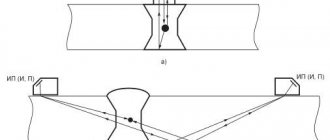
Longitudinal cracks are located along the welded joint and can be located:
- in the weld metal;
- in the main material;
- at the fusion boundary;
- in the area of temperature influence.
Longitudinal crack
Cracks in the base metal, caused by high stresses, are called hidden. Outwardly, they resemble steps. This defect is inherent in welded joints of considerable thickness. High voltages are caused by joints that are too rigid or by incorrect selection of welding technology. Reducing welding stresses reduces the likelihood of hidden longitudinal cracks.
The configuration of longitudinal cracks is determined by the fusion lines of the weld and the base metal.
These cracks are divided into:
- hot, their cause is the high-temperature brittleness of the alloys;
- cold - occur during the slow destruction of metal.
Transverse cracks are oriented perpendicular to the axis of the weld. They can occur both in the base material and metal of the welded joint, and in the temperature-affected zone.
Radial cracks diverge from one point and are otherwise called star-shaped. Their locations are similar to the locations of transverse cracks. The reasons for the formation of transverse and radial cracks are the same as for longitudinal ones.
At the point where the arc is torn off, a depression is formed on the surface of the seam. Defects that occur at this location are called crater cracks. They are divided into longitudinal, transverse, star-shaped. The configuration of this defect is determined by: the microstructure of the welded joint zone, phase, thermal and mechanical stresses.
If a group of cracks not connected to each other occurs, then they are called separate. The locations and causes of their occurrence are similar to these characteristics of transverse and radial cracks.
If a group of cracks is formed from one crack, then such a marriage is called branched cracks. Their locations are the base material, weld metal, and thermally affected area. The causes of occurrence are the same as for longitudinal cracks.
Group 1. Cracks
100 E Cracksen cracks
fr fissures
Discontinuity caused by local rupture of a weld, which may occur as a result of cooling or loads 1001 Microcracken microfissure (microcrack)
fr microfissure
A crack having microscopic dimensions, which is detected by physical methods at no less than fifty-fold magnification 101 Ea Longitudinal cracken longitudinal crack
fr fissure longitudinale
A crack oriented parallel to the axis of the weld.It can be located:
1011 in weld metal; 1012 at the fusion boundary; 1013 in the heat affected zone; 1014 in base metal 102 Eb Transverse cracken transverse crack
fr fissure transversale
A crack oriented transverse to the axis of the weld. It can be located: 1021 in the weld metal; 1023 in the heat affected zone; 1024 in base metal 103 E Radial cracksen radiation cracks
fr fissures rayonnates
Cracks that radiate from one point. They can be: 1031 in the weld metal; 1033 in the heat affected zone; 1034 in base metalNote—Cracks of this type, diverging in different directions, are known as star cracks.
104 Ec Crack in the crateren crater cracks
fr fissure de cratere
A crack in the weld crater, which can be: 1045 longitudinal; 1046 transverse; 1047 star-shaped 105 E Separate cracksen group of disconnected cracks
fr reseau de fissures marbrees
A group of cracks that can be located: 1051 in the weld metal; 1053 in the heat affected zone; 1054 in the base metal 106 E Branched cracksen branching cracks
fr fissure ramifiees
A group of cracks arising from a single crack.They can be located:
1061 in weld metal; 1063 in the heat affected zone; 1064 in base metalPores: their shape, location and reasons for their appearance
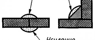
Defects in welded joints and joints in the form of cavities in a welded joint are called pores. These cavities are filled with gas that has not had time to escape.
The following types of pores are distinguished:
- A gas cavity is a formation of arbitrary shape, without corners, the cause of which was gases that did not have time to leave the molten material.
- A gas pore is a gas cavity that has a spherical shape.
- A group of gas pores located in the metal of a welded joint is called uniformly distributed porosity.
- A cluster of pores is three or more gas cavities located closely at a distance from each other not exceeding triple the diameter of the maximum pore.
- A chain of pores is a series of gas cavities that are located in a line along the welded joint with a distance between them not exceeding three diameters of the largest pore.
- If the defect is a discontinuity elongated along the axis of the weld and having a height that is much less than the length, then it is called an oblong cavity.
- A fistula is a tubular cavity located in the weld metal. A fistula is caused by the release of gas. Its shape and position are determined by the gas source and the hardening regime. As a rule, fistulas form clusters in the shape of fir trees.
- A gas cavity that violates the integrity of the surface of a welded joint is called a surface pore.
- If a cavity forms during hardening due to shrinkage, it is called a shrinkage cavity. A shrinkage cavity located at the end of the roller and not welded during subsequent passes is called a crater.
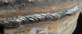
Pores - defects in welded joints, photos of which are given below, appear due to the presence of harmful impurities, both in the base metal and in the filler metal. Pores can form due to rust and other contaminants that were not removed from the edges of the material before welding, high carbon content, high speed of the welding process, and violations of the weld pool protection. The most common cause of pores is a damp coating of the consumable electrode.
The presence of single pores does not pose a danger, but their chain can negatively affect the strength characteristics of the welded joint. The area of the weld seam affected by these defects is digested, having previously mechanically cleaned it.
Pores and slag inclusions
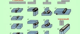
Types of welding defects, depending on the reasons for their occurrence
During fusion welding, defects in welded joints that arise, depending on the reasons for their occurrence, can be divided into two types. The first type of defects is associated with metallurgical processes during welding and with thermal phenomena that occur as a result of the formation and crystallization of the weld pool and cooling of the welded joint. These defects include hot and cold cracks in the metal and heat-affected zone, pores in the metal, non-metallic inclusions, as well as non-compliance of the properties of the deposited metal and the heat-affected zone with the specified parameters.
The second type of defects includes their types, the cause of which is a violation of the selected welding modes, violations during the preparation of welded elements and during their assembly, malfunctions of welding equipment, insufficient professionalism of the welder, as well as other violations of welding technology. Defects of this type include the discrepancy between the actual dimensions of the seams and the required ones. These are defects such as lack of fusion, undercuts, unfilled craters, burns in the metal being welded.
Types of solid inclusions in a weld
Solid foreign inclusions, both metallic and non-metallic in nature, having at least one acute angle in their configuration, are unacceptable defects in the welded joint, since they play the role of stress concentrators. An additional danger of these defects is that they are not visible from the outside. They can only be detected by non-destructive testing methods.
Slag inclusions in a welded joint
Solid inclusions are divided into the following types:
- Slag inclusions are slag trapped in the weld. Depending on the conditions under which they were formed, they can be linear, disconnected, or others. The reasons for their formation are high speeds of the welding process, contaminated edges, multi-layer welding, if the seams between the layers are poorly cleaned. The shape of these defective inclusions is very diverse, so they can be much more dangerous than round pores.
- Fluxes, which serve to protect the metal from oxidation, cause the formation of flux inclusions. Just like slag inclusions, flux inclusions are divided into linear, isolated and others.
- The reasons for the formation of oxide inclusions can be: an insufficiently clean surface of the base or filler metals, pulling a hot welding rod out of the gas protection area, improper preparation of the edges - their dullness is too strong.
- Particles of foreign metals - tungsten, copper or others form metallic inclusions. The reason for their formation can be erosion of the tungsten electrode or accidental ingress of metal particles from the outside, as well as when copper shavings are used for ignition.
Group 3. Solid inclusions
300 Hard inclusionen solid inclusion
fr inclusion solide
Solid foreign substances of metallic or non-metallic origin in the weld metal. Inclusions that have at least one acute angle are called acute-angled inclusions 301 Va Slag inclusionen slag inclusion
fr inclusion de laitier
Slag trapped in the weld metal. Depending on the conditions of formation, such inclusions can be: 3011 linear; 3012 disunited; 3013 other 302 G Flux inclusionen flux inclusion
fr inclusion de dlux
Flux trapped in the weld metal. Depending on the conditions of formation, such inclusions can be: See 3011-3013 3021 linear; 3022 disconnected; 3023 other 303 J Oxide inclusionen oxide inclusion
fr inclusion d'oxyde
Metal oxide introduced into the weld metal during solidification 304 N Metal inclusionen metallic inclusion
fr inclusion metallique
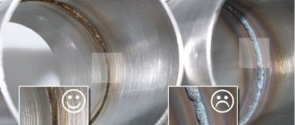
A foreign metal particle embedded in the weld metal. Particles are distinguished from: 3041 tungsten; 3042 copper; 3043 other metalLack of fusion and lack of penetration: causes
Lack of fusion and lack of fusion
Defects - lack of fusion and lack of fusion - are the lack of connection between the base material and the metal of the welded joint.
Non-fusion occurs at high speeds of the welding process and current strengths of more than 15000C. To prevent non-fusion, it is necessary to reduce the welding speed, reduce the time gap between the formation and filling of the groove, and thoroughly clean the welding area from oils and contaminants. Non-fusion can be located:
- at the root of the weld;
- on the side;
- between the rollers.
Lack of penetration occurs due to the inability of the molten metal to reach the root of the weld. There may be several reasons for lack of penetration:
- insufficient welding current;
- electrode movement speed is too high;
- increased arc length;
- the bevel angle is too small;
- distortion of welded edges;
- insufficient gap between edges;
- incorrectly selected – increased – electrode diameter.
- slag getting into the gaps between the edges;
- inadequate choice of polarity for this type of electrodes.
Lack of penetration is a very dangerous and unacceptable welding defect.
A DIY resistance welding machine is a great option if you want to save money. If you often make barbecues, then a grill that you can make yourself will be useful to you. Detailed instructions in this article.
Don't know what you need for gas welding? For a detailed list of required materials, follow the link.
How to fix a lack of fusion defect
When high strength requirements are not imposed on a welded joint, the product can be accepted for service if a minor defect is located along the direction of the load. The shape and depth of the flaw is also taken into account. If the lack of penetration of the weld is accessible for welding, it is cleaned and welded. When installing critical structures, the rejected area is cut down or cut out, and after preparation it is welded again.
Regulatory documents allow the formation of lack of penetration if they do not exceed the established limits. Therefore, novice welders should not be afraid of defects; the main thing is to eliminate them in a timely manner. Knowing the reasons for the formation of lack of penetration, you can quickly learn to identify the places where they appear.
Types of deviations of the shape of the outer surface of the seam from the specified values
The following defects are considered to be defects in the shape of the weld:
- Continuous undercuts are continuous indentations located on the outer part of the seam bead. If undercuts are located on the root side of a single-sided weld and are formed due to shrinkage along the boundary, they are called shrinkage grooves. Undercuts are common surface defects that occur due to too high arc voltage when welding fillet welds or due to inaccurate electrode guidance. In this case, one of the edges is melted more deeply, which leads to metal flowing onto the part in a horizontal position. There is not enough metal to fill the groove. When welding butt seams, undercuts are rarely formed. If the welding speed and arc voltage are too high, double-sided undercuts usually occur. The same type of defect occurs during automatic welding if the cutting angle is increased.
- Excess of convexity of a butt or fillet weld represents an excess of deposited metal on the face of the welds in excess of the required value.
- If an excess of deposited metal in excess of the established value is located on the reverse side of the butt weld, then such a defect is called excess penetration. A variation is local excess melting.
- If excess deposited metal flows onto the base metal, but does not fuse with it, then such a defect is called overlay.
- Linear displacement occurs if the surfaces to be welded are parallel, but not at the same level.
- Angular is the displacement between two surfaces when they are located at an angle that differs from the required one.
- Sagging is formed from weld metal that settles under the influence of gravity. Sagging occurs in horizontal, overhead, bottom welding positions, in corner joints, and in lap joint welds.
- When a burn occurs, the metal of the weld pool flows out, forming a through hole. The causes of burn-through may be contamination of the surface of the base metal or electrode.
- Incomplete filling of the edge groove occurs due to insufficient filler material.
- If in a corner joint one leg is significantly larger than the other, then a defect of excessive asymmetry occurs.
- Uneven weld width.
- An uneven surface is the unevenness of the shape of the reinforcement of the seam along its length.
- A weld root concavity is a shallow groove on the root side of a weld that is formed due to shrinkage.
- Due to the appearance of bubbles during the solidification of the metal, porosity is formed at the root of the weld.
- Resumption. This defect is a local surface roughness in the zone where the welding process is resumed.
Overlap and undercut
Elimination and prevention of welding defects
When eliminating a welding defect in the form of lack of fusion, the root at the defect site is cleaned and welding is carried out again. During installations of important structures, the defective area is cut down or cut out and then welded again.
The following methods will help prevent lack of penetration in welds:
Edge cutting
A method where edges are pre-cut at a certain angle. In this case, free contact of the electrode to the root of the seam and dullness are left. In the right place, dirt, oxide, rust are cleaned and the surface is degreased. The prepared parts are placed evenly in one plane, leaving a gap between the edges.
You can read more about preparing metal for welding here.
Heat supply
A method when the welding speed is set so that the metal of the edges has time to melt, since during the rapid movement of the electrode the heat is only enough for seam formation. When welding parts repeatedly, remove the slag after all passes, as it will interfere with the melting of the previous seam.
Alternately following welding modes
Setting a medium or high current value that will correspond to the thickness and metal of the prepared parts. To avoid lack of fusion at the ends of the seam and when replacing the electrode, inverters regulate the function of increasing the voltage for a short time. To prevent non-fusion on an old welding device without adjusting the arc parameters, select the time to detect minimal fluctuations in the mains voltage.
Correct electrode position
When welding, the arc is drawn along the axis of the joint to heat both edges equally. Failure to do this will prevent the edge from fusing to the seam. The electrode is moved forward at an angle of 5-20 degrees. When welding fillet welds with a boat, the electrode is held at the same distance from the surface of the parts. When the workpieces are connected into an asymmetrical “boat”, the electrode is placed at an angle of 30 degrees to one of the planes of the parts.
Weld parts at high current with direct or reverse polarity. When welding with reverse polarity current, a short arc is used, which can cause undercuts. And due to the large diameter of the electrode, slag particles can get into the edge gap.
Refractory oxides
These are components formed when alloys and alloy steel are heated. If the elements are welded incorrectly, the slag remains inside the seam, forming defects in the form of lack of fusion. To prevent this, oxygen is needed to form oxides. When using a consumable electrode, it is worth choosing a device with a coating that matches the type of metal.
Now overcoming local lack of penetration should not frighten novice welders. The main thing is not to create reasons conducive to its formation. If it could not be avoided, the defect can be eliminated, but it is better to try to prevent the occurrence of non-fusion.
Other weld defects
All defects in welds and joints that are not listed above are classified as “other”. These include the following types of defects:
- Random arc. As a result of accidental arcing, local damage occurs to the surface layer of the base metal adjacent to the weld area.
- Metal spatter is droplets that are formed from weld metal or filler metal during the welding process. They stick to the surface of the cooled weld metal or base metal located in the heat-affected area.
- Tungsten spatter - created by particles of tungsten thrown from the molten electrode onto the base metal or onto the weld.
- Surface scoring is a defect that occurs due to the removal of a temporarily welded fixture.
- Thinning of the metal occurs during machining. In this case, the thickness of the metal has a value that is less than the permissible value.
Permissible defects in welded joints are deviations, the presence of which does not reduce the operational properties of the welded joint and their presence is permitted by regulatory documentation. All other defects, as a rule, can be corrected by welding. It is not allowed to correct the quality of welding more than twice, as overheating or burnout of the metal may occur.
General principles for classifying defects
Weld defects are divided into internal and external. Internal defects include unfavorable deviations from microhardness and structure that are identified in the weld. External defects include those that are detected by visual inspection. In practice, major weld defects are examined and evaluated in comparison with perfectly executed welds on workpieces made of the same materials.
An important principle of classification is the characteristic features of defects, which can relate either to the quality of the seam, or to its unacceptable shape or size.
The first group of defects includes:
- Existing gas inclusions (bubbles);
- Inclusions of slag, flux or metal particles;
- Seam discontinuities.
The second group includes:
- Distortion of the root of the seam (undercut);
- Cracks of various spatial orientations;
- Other surface defects, for example, burn-through grooves, sagging, uneven surface of the seam, etc.;
- Inadmissible displacement of the axes of the workpieces being welded.
GOST 30242-97 establishes that these defects are often the result of non-compliance with technological welding conditions and subsequent thermal/mechanical treatment of the finished welded joint. At the same time, defects that may be caused by the low-technological nature of the welded structure must be prevented even at the stage of pilot testing of such a structure.
Drawings and photographs of specific defects are usually provided in the texts of the relevant regulatory documents.
Acceptable and unacceptable defects
It is clear that all defects in welded joints negatively affect the quality of the welded structure. But there are those in which the structure can be operated without problems, and there are those in which its operation is strictly prohibited.
Therefore, before determining whether a welded structure can or cannot be used, it is necessary to take into account all the circumstances and factors influencing the choice.
- It is necessary to determine whether the design complies with all geometric and dimensional parameters strictly according to the project or drawing.
- Type of defect, its size and location in the connection.
- What mechanical loads will the building or structure be subjected to? Will their welding joints hold up?
- Nature of the environment. Natural loads negatively affect the condition of the weld.
- Functions assigned to the structure. That is, one defect can withstand certain loads, while others are contraindicated.
The admissibility of defects can only be determined using special equipment. Therefore, it is recommended to use equipment that, in terms of the degree of verification of the defect, was higher than the nominal permissible value of the defect itself. For example, a 3 mm crack cannot be measured with a device that detects minimum cracks of 5 mm in length.
By the way, admissibility is influenced not only by the size and shape of defects, but also by their number and frequency of location.
Microstructure defects
Microstructure defects include microscopic cracks and pores, inclusions of non-metallic type (oxygen, nitride), coarse grain structure of the deposited metal with elements of overheating and burnout.
The most dangerous of all the listed defects is burnout. With it, large grains of the metal structure appear in large numbers inside the seam, which have minimal strength connections with each other. Hence the high fragility of the joint. The causes of burnout are the presence of oxygen in the welding zone, which means that the insulation of the bath was poor. Here you can add the high temperature of the welding process.
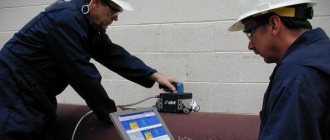
How to detect weld defects
After completing the work, it is necessary to evaluate the quality of the seams.
To identify flaws and control the quality of welded joints, the following methods are used:
- Visual inspection. During the procedure, a magnifying device is used. The method helps to identify large and medium-sized defects.
- Color flaw detection. It is based on the ability of a metal to change its shade when it comes into contact with certain liquids, such as kerosene.
- Magnetic method. Involves determining the nature of wave changes.
- Ultrasonic testing. It involves the use of special equipment capable of determining the nature of the reflection of sound waves.
- Radiation diagnostics. Defects are detected by scanning the joint with X-rays. The resulting snapshot shows all invalid elements.