Article reading time: 20 minutes
Author of the article:
Riveted connection of parts is widely used in construction, mechanical engineering, instrument making and many other industries. Rivets are a wide category of hardware that allows you to create strong and rigid permanent connections. The mounting units are designed for high durability under significant operating loads. Let's look at the main features, advantages and disadvantages of rivet joints.
Types of rivets
Today, two types of rivets are most widespread. Let's take a closer look at them.
Hammer rivets
A feature of hammer rivets (they are also called “impact” or “driving”) is the need for access to the mating structural elements from both sides. Several domestic State standards regulate the production of fasteners of this type:
- GOST 10299 from 1980. It establishes the technical specifications of rivets with a cylindrical shank and a hemispherical head;
- GOST 10300, adopted in the same 1980. Its provisions guide metallurgical enterprises that produce rivets with a core configuration similar to the previous version, but with a countersunk head.
- GOST 10301-80. This regulatory document applies to rivets with a cylindrical shank and a semi-countersunk head.
Below is the appearance of these fasteners.
The range of change in the diameter of the shank of rivets made according to the requirements of the first two standards is completely the same: min1.0 mm; max 36.0 mm. But the range of values for this parameter of fasteners corresponding to the provisions of GOST 10301 is a little shorter: although the upper limit is the same - 36.0 mm, the minimum value is 2.0 mm. Other technical characteristics, starting with the diameter of the head, including its height, and ending with the radius of the transition of the supporting surface of the head into the rod, differ in all three regulatory documents.
Blind rivets
To install these fasteners, it is sufficient to have access only from one side of the mating elements. This procedure is performed using a special tool called a “riveter”. Enterprises whose product range includes blind rivets, in their production are guided by the standards of GOST P ISO 15977-2017, as well as the generally accepted German standard DIN 7337.
The following materials are used as raw materials for their manufacture:
- aluminum alloys;
- zinc-containing copper-based alloy – brass;
- metal copper (Cu);
- stainless steel grades A4, A2, as well as their domestic analogues 10Х17Н13M2 and 08Х18H10, respectively;
- carbon steel;
- polyamide.
You can get acquainted with the principle of operation of blind rivets by watching a short video. Its launch is very simple: the cursor is hovered over the picture below, and then the actions indicated in the displayed hint are performed.
Kernel
Based on its shape, the following types are distinguished:
- solid;
- hollow (have a through hole);
- semi-hollow - the rod is divided into two parts: one is solid and the other is hollow.
Basic information about fastenings and components is contained in the regulatory documentation.
GOST 10303-68, which characterizes rivet joints, includes the main standard sizes of rivets. Its diameter, length of the body and rod, as well as the type of head are specified here.
Types of connections depending on purpose
The area where parts are connected using rivets is called a rivet seam. Depending on the scope of application and design features, rivet seams are divided into the following types:
- The seams are strong. Their increased strength is ensured by the formation of several rows of rivets. Such seams are usually used when riveting bridge structures, columns - gable supports, linear elements of load-bearing structures - beams, etc.;
- The seams are tight. On their basis, sealed structures (for example, reservoirs for liquids) are created that operate under small external loads. Connections to this seam are usually made using the cold riveting method. Its tightness is ensured by using paper or fabric gaskets, pre-impregnated with drying oil or a chemically resistant substance such as red lead. Another option is to emboss the seam;
- The seams are strong and tight. They are formed by riveting individual components of steam boilers, tanks, vessels, pipelines operating under relatively high pressure. The method for making durable seams is hot riveting. For this purpose, riveting machines are used, both stationary and portable. The final stage of this technology involves embossing the edges of the plates and rivet heads.
Stages of work
Stages:
- Preparation of parts to be joined.
- Marking holes.
- Drilling holes.
- Countersinking of finished nests.
- Installation of fasteners.
- Crimping
Before starting the main stages of work, you must:
- Clean surfaces from plaque, dirt, and rust.
- Mark the locations of future holes. Before drilling, they need to be marked so that the drill does not go to the side.
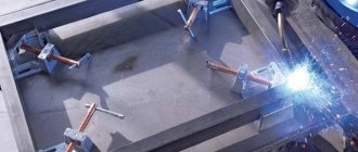
Preparation of metal structures (Photo: Instagram / start_blasting)
Drilling holes
You can drill holes in metal surfaces using a drill press or hand-held power tool. It is better to use a drill press because it can drill holes in thicker parts.
When using a hand-held power tool, it is important to accurately control its position when drilling so that it does not deviate to the sides. When drilling, it is necessary to use special coolants. You can only work with a sharpened drill.
Inserting rivets
Stages:
- The fastening element is inserted into the hole with the rod from bottom to top.
- A support is installed under the embedding head. If it is hidden, it is necessary to use flat support.
- The parts are compacted. They are seated at the riveting site. Gaps between metal sheets are eliminated with a hammer.
Formation of the closing head
How to do it:
- Direct method. Hammer blows are applied to the rivet shaft from the side where the closing head is formed.
- Reverse method. The hammer blows are applied to the mortgage head.
Bench hammers (Photo: Instagram / inforce_tools)
Types of connections depending on design features
According to the “design features” criterion, riveted connections can be single- or double-sided.
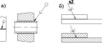
For clarity, the corresponding pictures are posted below. This is how one-sided overlapping fastening is performed. Everything is very simple here: one plate is placed on top of the other, a through hole is drilled into them, into which the rivet rod is installed, and its protruding end is riveted until the closing head of the desired shape is obtained. This is also a one-way type fastening. But in this case, one overlay is placed on top of the adjacent plates. The rods of two rivets are threaded into through holes drilled in both sheets and in the overlay, and then two closing heads are formed in the same way as in the previous version.
This figure shows an example of a double-sided rivet connection. One overlay is placed on top and bottom of the plates pressed end to end. And then the actions are carried out according to the previous algorithm, only the rivet rod pierces the holes in three structural elements - in the lower plate, in the part being fastened and in the upper plate.
Structure
Riveted connections consist of three elements:
- two parts of connected parts;
- rivet.
The last element is placed in special holes, which are located at the edges of the parts to be connected.
The rivet holds the parts in the required position. In this case, the fastening element has the following structure:
- body;
- kernel;
- embedded head – used to form the future product;
- closing head - formed in the process of connecting two elements.
A huge number of rivets are used to fasten large parts together. In this case, the finished connection will be called a rivet seam.
Rules for creating rivet joints
In order for the rivet connection to be reliable, it must be carried out taking into account the recommendations of professionals. The picture below will help you understand this issue.
- The processing of holes in the parts to be fastened should be carried out together. Misalignment of the sockets will cause a sharp weakening of the rivet (Fig. “a”).
- In critical connections, holes should also be subjected to a joint reaming operation. The rivet itself must be installed under tension (Fig. “b”).
- These fasteners should not be located in places with limited space (Fig. “c”). There should be enough space around them for convenient use of riveting devices. The distance (Fig. “d”) of the longitudinal axis of the installed rivet to nearby vertical walls (L) should be in the case of using: hydraulic riveting: L= (1.5-2.0) × d; pneumatic riveting: L= (2.0-2.5) × d, where d is the diameter of the fastener rod.
- It is especially important that free access is provided to the closing head, as shown in Fig. "g" (indicated by the symbols "e1"). Place according to the principle of Fig. "d" is inappropriate.
- In adjacent rivet seams, where the axes of the fasteners are located parallel to each other (Fig. “d”, “g” and “h”) or perpendicular (Fig. “i”, “j”), it is better to place the rivets in a checkerboard pattern order (Fig. “h”, “k”). Then performing the riveting procedure will become much more convenient (read, easier).
- To eliminate the need to use a large riveting device, which is also characterized by a large reach, a special approach is needed. It consists in minimizing the distance from the extreme edges framing the mating parts to the axes of the rivets. Let's consider an example when it is necessary to connect the bottoms of cylindrical containers with shells. In this case, it is advisable to use bottoms in which the flanging is made not inward (Fig. “l”), but outward (Fig. “m”), even despite the lower strength of the formed connection.
- When the rivet is installed on an inclined plane (Fig. “n”), the following options are allowed: place the rivet under the countersunk (Fig. “p”); make flat cuts on inclined supporting surfaces (Fig. “o”); use hot riveting. This requires heating the entire body of the rivet.
- The previous rule also applies to cases of installing rivets on a cylindrical surface (Fig. “p”, Fig. “c”).
- When riveting elements that require maintaining precise dimensional characteristics using a cold method (for example, when the rims of gear wheels are riveted to disks, Fig. “m”), it is necessary to take into account the fact that the walls under the influence of forces arising during riveting can be deformed (manifested This phenomenon is especially true for rivets with countersunk heads). The experts' recommendation in this case sounds like this: those areas of the material that are subject to the greatest deformation during riveting should be separated by a gap s from surfaces with precise dimensions (Fig. “y”).
Rivet connections. Advantages and disadvantages of the bonding method
Among the positive aspects are:
- simple technological design;
- ability to connect dissimilar metals;
- high connection reliability;
- resists vibration and shock loads.
However, like every connection, it has its downsides, including the following:
- to create a rivet fastening, it is necessary to spend a large amount of metal;
- requires significant labor costs;
- high price;
- rivet joints can be destroyed due to the incorrect diameter of the holes that are located at the edges of the products;
- During operation, the tightness of the connection decreases.
There are quite a few types of rivet joints, since each of them is used in a specific industry.
Hello student
General information
Riveted connections belong to the class of permanent connections.
They are one of the most common and reliable methods of connecting parts in general mechanical engineering, shipbuilding, and especially in the design of aircraft. For example, in a wide-body aircraft, up to 75% of all connections are made using rivets. On the IL-86 aircraft, the total number of rivets reaches almost 1.5 million pieces.
The advantages of riveted connections include the possibility of using:
□ for connecting non-weldable parts;
□ in critical structures that endure large vibration or repeated loads;
□ in structures that do not allow welding due to warping or the danger of tempering of heat-treated parts.
In addition, riveted joints are more stable and better controlled than welded ones.
The disadvantages of riveted joints are:
□ large mass of the connection;
□ higher manufacturing cost;
□ increased metal consumption;
□ noise and vibration during the manual riveting process.
The rivet is a rod of round cross-section with a rivet head at the end. The embedded head 1 is made simultaneously with the rod, and the closing head 2 is formed during riveting. The diameter of the hole for the rivet in the parts to be joined is made 0.2... 0.5 mm larger than the diameter of the rivet rod. As a result of riveting, the rivet shank settles and tightly fills the hole. The most widely used are solid bar rivets for general machine-building applications with a rivet head of various shapes, the closing head of which is formed by pressing or impact. In press riveting, the closing head of the rivet is formed by uniform compression of the rod on semi-automatic presses and riveting machines.
There is a distinction between single and group riveting, in which several rivets are riveted in one press stroke, which significantly increases productivity. Impact riveting is performed using pneumatic riveting hammers. The formation of the closing head occurs during the process of impact and upset of the rivet rod. The quality of press riveting is higher than impact riveting. Therefore, when designing riveted connections, the possibility of using both single and group press rivets for rivets with a flat or countersunk head is taken into account.
In connections streamlined by air flow, rivets with a countersunk head with a cone angle a = 90° at d = 10 mm and a = 120° at d = 2... 6 mm are used. The method of making sockets for the heads of countersunk rivets depends on the thickness of the parts being connected. When the thickness of the skin is greater than the height of the embedded head, the nest is formed by countersinking; for skins with b < 1.2 mm - by stamping or stamping of the skin and countersinking of the frame. When the thickness of the skin is less than the height of the head, rivets with a = 120° are used.
To connect parts made of composite materials (fiberglass laminates, carbon fiber reinforced plastics, etc.), semi-hollow and hollow metal rivets d = = 1... 10 mm are used. A blind hole in the shank of a semi-hollow rivet reduces the riveting force, reduces the increase in the diameter of the rivet shank and increases the durability of the connection. Hollow rivets are intended for connecting parts made of elastic materials and for non-force connections of metal parts.
Rivets are made from aluminum alloys (V65, D18P, D19P, AMg5P, etc.), steels (10, 15, 20G2, 12Kh18N9T, ZOKHMA), brass (L63) and copper (M2). When connecting parts made of light alloys, as well as light alloys and steel, it is recommended to use rivets made of aluminum alloys, since the large riveting forces required to rivet steel rivets cause significant deformation of parts made of light alloys. The most common rivets are made from alloy B65. In structures operating at 150...250 °C, rivets made of D19P alloy are used. To connect parts made of deformable alloys AMts, AMgZ and non-metallic materials, rivets made of ductile aluminum alloy AMg5P are used. Parts made of titanium alloys and steels are connected with steel rivets. Rivets made of corrosion-resistant steel 12Х18Н9Т are used to ensure corrosion resistance of the connection, also at temperatures above 250 °C.
Rice. 1
Rice. 2
Rivets made of light alloys and steel rivets d < 10 mm are cold riveted. Large-diameter steel rivets are riveted using the hot method—by heating the end of the rivet.
In aviation technology, along with solid rivets for general use, various types of special rivets are used (OST 1).
In power connections where significant shear forces are applied and the strength of light alloy rivets is insufficient, rivets with high shear resistance are used. Rod 1 of such a rivet (d = 5... 12 mm) is made of steel 25KhGSA or ZOKHGSA, and ring 2 is made of aluminum alloy D18. The formation of the closing head occurs by compressing ring 2 around the annular recess of rod 1. When forming a connection with these rivets, the rod does not settle - it must be placed in a hole machined with a reamer with an H8 tolerance.
It is recommended to use rivet bolts instead of a bolt with a nut if there are approaches to the connection for the use of a special tool. An aluminum alloy rod with a diameter d = 3, 5... 10 mm has a smooth cylindrical section, equal in length to the thickness of the package, and a section with knurled annular ribs and a tear-off neck. The crimp ring is made of aluminum alloy or mild steel. The installation of rivet bolts is not accompanied by noise and vibration, the mass of such a connection is 1.2... 1.5 times less, and the fatigue tensile strength is 2 times higher than that of a bolted connection made of the corresponding materials.
For one-way access to the riveting area, explosive rivets, core rivets and cap nuts are used. Explosive rivets have a chamber 3 at the end of the rod, which is filled with an explosive substance. The rivet is placed in place in a cold state and heated to 500 ° C, an explosion occurs in the chamber, unfolding the free end of the rod.
Rivets with a core consist of two parts - a piston with a countersunk or semicircular head 3 (from D18P or 1X18N9T) and a core 4 (from D16P or 3X13). The formation of the closing head occurs when the core is pulled through the piston hole. The protruding part of the core comes off.
Piston nuts consist of a thin-walled piston with an internal thread in its end part. When the screw is turned, the thin wall of the piston is deformed, forming the closing head of the rivet.
A connection made by a group of rivets is called a rivet seam. According to the design, rivet seams are made overlapped, end-to-end with one overlay and two overlays. The rivets in the connection are arranged in rows or in a checkerboard pattern.
Depending on the number of rivet sections working for shear, the connection can be single-cut or double-cut. In the design of aircraft, single-shear joints are mainly used. According to their purpose, rivet joints are divided into strong and durable. Strong connections serve to provide strength, absorb external load and transfer it from one element to another. Strong-tight connections, while withstanding significant forces, also ensure tightness (riveted tanks, sealed cabins, etc.).
The butt joint with one overlay is the most common joint in aircraft and helicopter structures. It is used to connect the external streamlined skin with stringers, spars, frames, etc. In combination with secret riveting, this connection meets the requirements of modern aerodynamics. Structural elements that transmit large forces, such as spars, frames, beams, landing gear components, etc., are butt-joined with two overlays. Overlap joints are used to fasten electrical equipment elements and other units inside the airframe.
Literature used: Machine parts and design fundamentals: textbook. for universities / G. I. Roshchin, E. A. Samoilov, N. A. Alekseeva and others; edited by G. I. Roshchin and E. A. Samoilova. - M.: Bustard, 2006. - 415, [1] p.: ill. - (Higher education).
Download abstract: You do not have access to download files from our server. HOW TO DOWNLOAD HERE
Archive password: privetstudent.com